Anand Kumar Myla* | Srinivasa Rao Gorantla
© 2023 IIETA. This article is published by IIETA and is licensed under the CC BY 4.0 license (http://creativecommons.org/licenses/by/4.0/).
OPEN ACCESS
Standalone Microgrid has implemented in Mat-lab/Simulink platform, which has two Dispersed generation units based on a Solar Photovoltaic Generation and Wind Turbine Generation, how to get the most of wind and solar energy by lowering investment and operating expenses based on load power demand. The goal is to reduce one-time investment and operation expenses over the lifecycle; the limits are utilization rate and power supply reliability. The proposed system advantages, if Solar Photovoltaic Generation is absent, Wind Turbine Generation meets the load power demand, in case of a crucial situation, if Wind Turbine Generation is also absent, then Energy Storage System meets the load power demand, which means the power supply is reliable to the remote areas/limited load demand, besides in proposed system converters are reduced, so investment reduces. Mathematical models of Solar Photovoltaic Generation and Wind Turbine Generation are presented, to achieve Maximum Power Point Tracking of a Solar Photovoltaic Array, the Perturb and Observe method is used. Proportional-Integral controller used for Wind Turbine Generation, Solar Photovoltaic Generation, and Energy Storage System-based Direct Current/Direct Current Bi-directional Converter. An effective inductance filter is used for the mitigation of harmonics in the system. The finest simulation results are obtained, it concludes the system is in balanced condition under various loads with the Proportional-Integral controller and current total harmonic distortions are within limits.
dispersed generation (DPG), energy storage system (ESS), L filter, maximum power point tracking (MPPT), proportional-integral (PI) controller, solar photovoltaic generation (SPVG), standalone microgrid (SMG), wind turbine generation (WTG)
Every country is shifting to renewable energy sources (RESs) because of the greenhouse emissions. SPVA and wind energy are popular among other RESs [1],[2]. The majority of these renewable energy sources function as MGs. Because MG improves the system’s quality and dependability [3]. Distributed generation has recently been a very hot research subject due to the significant advantages of DG over traditional centralized power generation [4]. Integrating RESs into the present power system via a DG platform has piqued interest [5]. MGs can function in three different modes: gridconnected, islanded and transitioning between them [6]. There are a number of obstacles to providing reliable MG operation, notably in the IM [7]. The MG in the IM must be able to balance power and deliver load currents, which may include various harmonics and disturbances. Otherwise, the voltage at the load will be greatly distorted, which can be dangerous for sensitive loads or even induce voltage collapse in extreme circumstances. As a result, proper load balancing (including harmonics) is critical to the reliability of MGs [8]. Virtual impedance, frequency droop, and angle droop regulation have all been mentioned in the literature to ensure system stability and load sharing across several generators in SMG [9].
DPG units, local grid factors, controls, and linked loads all affect power quality in SMG [10]. Harmonics mitigation requires both passive and active filters. Many strategies for active filtering have been presented, including instantaneous power theory, synchronous reference frame methodology, adaptive control, and so on [11]. Battery storage systems were combined with the MG in numerous distribution renewable energy generating systems (DREGS) with various control strategies to alleviate system instabilities [12],[13]. ESS is required to deal with the stochastic nature of the major renewable energy sources (solar and wind), as well as to provide the load profile while maintaining stability and reliability. In the near term, ESS serves as a grid-supporting entity, ensuring system security and energy supply amid load fluctuations. Long-term, ESS is utilized to fulfill load demand when generation capacity is insufficient. To combat energy shortages, batteries are commonly utilized for storage in medium and small-scale energy systems. Furthermore, the battery storage system (BSS) can be used to accommodate the RES’s abrupt load or dynamic behavior. Finally, batteries are more convenient to use and are popular worldwide [14]. In the IM of operation, the storage battery is incorporated into the RES-based DGs. The storage battery is important, according to Alsaidan et al. [15] and Datta et al. [16] in islanded DGs. Battery storage is essential in standalone Photovoltaic applications due to the intermittent nature of PV power [17]. In some grid-connected installations, battery storage is employed to enable the PV system to function in independent mode to serve local loads during grid outages [18].
The PI control method especially in the islanded mode [25]. The number of series-connected PV panels and one common MPPT [26]. Some of the downsides of SPV are addressed to extract peak power from the system. For that MPPT algorithms are used for better yielding of output power [27]. To generate electricity from the solar energy source, photovoltaic (PV) modules technologies are used [28]. The reliability-oriented performance assessment of hybrid switch i.e., Hybrid Silicon-Silicon Carbide IGBT for Photo Voltaic applications is presented [30]. The structure of photovoltaic cells is studied and proposed the algorithm for MPPT is presented [31]. The realization of the network is an important aspect in the research on extremely thin absorber for application in the technology of 3D solar cells [32]. A Solar- Hydrogen system usually consists of providing electric energy to an electrolyzer by means of a solar panel array of photovoltaic system. Further, this system generally uses batteries and DC-DC converters to modulate and condition the electrolyzer voltage [33].
Where PV system alone installed for meeting load demand, it can supply the power in sunny time, during the night PV system generates zero power, this problem is overcome by the proposed system or this system significance is, it reliable in balancing the system and continuous in supplying the load power demand during the night with wind generation system, even if total generation is inadequate to meet the load power demand at the crucial situation, then ESS works as a backup energy source and meet that demand. In the proposed system, the ESS is treated as a single storage system to balance generation and loads in islanded mode. Besides, would like to mention that, combining the two DPGs (SPVG & WTG) in this paper, could generate more power or increase the capacity of the system when compared to the established individual system capacities of respective generations. The proposed system, based on SPVG-WTG-BATTERY used the least possible converters including only one inverter i.e., VSC is used (the system to work efficiently i.e., for easy synchronization of the above subsystems are combined at the DC side), when compared to the same system synchronization at AC side converters requirement/investment or the above individual systems power conversion converters requirement/investment. Thereby concluding that the proposed system reduces one-time investment.
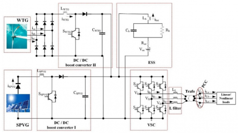
In this paper, the SMG configuration-based two DPG units - SPVG & WTG with ESS-based DC/DC BDC, are presented, for the reliable power supply or uninterrupted power supply in remote and isolated areas, thereby electric utility rate increases with RESs and with reduced power converters, an SMG configuration is developed, which in terms of reducing the investment. ESS or DC/DC BDC battery bank (as shown in Figure 1) is only a source of backup energy and an effective L filter is used to reduce harmonics with no losses.
This paper is organized as follows. The proposed SPVGWTG- BATTERY-based SMG configuration is presented in section 2. Section 3: describes mathematical modeling for SPVG System. In section 4, mathematical modeling for WTG system. Section 5, is simulation results and discussions. Finally, section 6 is the conclusions.
The proposed configuration, which has SPVG and a permanent magnet synchronous machine driven by WTG, is shown in Figure 1. To make easy synchronization for various DPG units integration, a diode bridge rectifier rectifies the power from the WTG and feeds it to the DC PCC through a boost converter II, and boost converter I connect the SPVG to the same dc-link. The combined dc power is fed to the PCC through a three-phase VSC (Universal bridge i.e., universal three-phase power converter that consists of six IGBT switches connected in a bridge configuration as shown in Figure 1). The SMG is strengthened by ESS or a battery bankbased DC/DC BDC. DC Synchronization of SPVG, WTG, and ESS is made effectively and in order to reduce harmonics at PCC, an effective L filter is used. A delta-star transformer is used to ensure galvanic isolation between the load and the rest of the system.
The presented system works based on the generated power from SPVG & WTG, as well as the load power demand. If the generated power from SPVG & WTG, is greater than the load power demand, ESS is in the charging mode. In case power from SPVG & WTG is less than the load power demand, then ESS starts discharging, i.e., to balance the power in the system, supplying power to the load. During the night, generated power from SPVG is absent, so generated power from WTG meets the load power demand. In case of a crucial situation, if generated power from WTG is also absent, then ESS meets the load power demand, meanwhile restoration works can be carried out.
Figure 1. Proposed SMG configuration
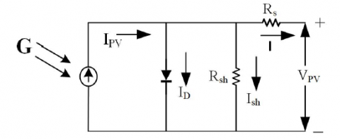
Figure 2. Equivalent circuit of Solar Photovoltaic panel
A PV cell’s operation is based on the photoelectric effect’s basic principle. The photoelectric effect is a phenomena in which an electron is released from a conductive band as a result of matter absorbing sunlight of a specific wavelength and is then conducted [19].
The corresponding SPV equivalent model is presented in Figure 2 [20] or [21], a current source, a diode, series resistance (Rs), and shunt resistance (Rsh) are included in it. Standard spectral distributions are often used to assess SPVA. In most cases, we determine using standard test conditions (STC).
The STC is as follows:
Solar Irradiation = 1000(W/m2);
Spectral Density = 1.5 AM;
The temperature at which the cell functions = 25°C
The practical-world SPVAs are made up of several SPVM, and the observation of features at the terminals necessitates the inclusion of further parameters into the fundamental equations [20] or [21] is given below:
The current under illumination known as the photocurrent ($I_{p h}$). $I_{p h}$ is given as,
$I_{p h}=I_{s c s}+K_i \times(T-298) \times\left(\frac{G}{1000}\right)$ (1)
Under dark, the SPV system has a saturation current $\left(I_0\right)$. $I_0$ depends on each cell temperature and is given below,
$I_0=I_{r s} \times\left(\frac{T}{T_n}\right)^3 \times e^{\left[\frac{q \times E_{g o} \times\left(\frac{1}{T_n}-\frac{1}{T}\,\right)}{a \times b}\,\quad\right]}$ (2)
The reverse saturation current ($I_{r s}$) is a current produced by the small reverse voltage when pn junction diode is reverse biased. It is given by the following expression:
$I_{r s}=\frac{I_{s c s}}{e^{\left(\frac{q \times V_{o c s}}{a \times N_s \times b \times T}\quad\right)}\,\,\,-1}$ (3)
Shunt current $\left(I_{s h}\right)$ which is the current of SPV system when it generates a low –resistance for the electrical current value. The low-resistance is known as the shunt resistance. The variation of the shunt current withe outup voltgae, the serie resistnwce(Rs) and the shunt resistance is given by
$I_{s h}=\frac{V+\left(I \times R_s\right)}{R_{s h}}$ (4)
The current generated by the SPV system or the current we can get from a such system is the output current (I) . It is given by:
$I=I_{p h}-I_0\left[e^{\left(\frac{q \times\left(V+\left(I \times R_s\,\,\right)\right)}{a \times N_s \times b \times T}\quad\right)}-1\right]-I_{s h}$ (5)
Sungrid SG-175M5 (mono-crystalline) make of 175W Module is considered to develop the SPVM in Matlab/Simulink platform [22], and the datasheet parameter values cited in Table 1, were used to construct the module. The key specifications of Sungrid SG-175M5 SPVA are 25°C, 1.5 AM, and 1000(W/m2).
Table 1. Key electrical parameters of the Sungrid SG-175M5 SPVA/SPVG
|
Parameters |
Ratings |
|
Rated Power |
2.6kW |
|
Power Tolerance |
+5, -0 (%) |
|
Open Circuit Voltage ($\left.V_{o c s}\right)$ |
43.6 V |
|
Short Circuit Current $\left(I_{s c s}\right)$ |
5.48 A |
|
V maximum power point (VMPP) |
35.2 V |
|
I maximum power point (IMPP) |
4.97 A |
|
Max System Voltage (Vmax) |
1000 V |
|
Voltage Temperature Coefficient (of $V_{o c s}$ ) |
-0.38% (%/°C) |
|
Current Temperature Coefficient (of $I_{s c s}$ ) |
0.10% (%/°C) |
|
Power Temperature Coefficient (of $P_{\text {rated }}$) |
-0.47% (%/°C) |
|
Number of solar cells per SPVM $\left(N_c\right)$ |
36 |
|
Number of SPVMs connected in series $\left(N_s\right)$ |
15 |
|
Values for operation under standard test conditions (STC) |
|
Perturb and Observe, Incremental Conductance, Fuzzy Logic, and other MPPT approaches have been proposed in the literature. The P & O algorithm is popular and simple. In this study, the P & O technique is employed to extract the most energy from SPVG. SPVG voltage (VSPVG) and currents (ISPVG) are monitored and perturbed to track maximum power point. The change in power is calculated, from these monitored and perturbed data.
The MPPT unit takes VSPVG and ISPVG as inputs and outputs duty cycle. In the simulation circuit, the above MPPT unit is used as closed-loop control.
One of the most critical parameters determining wind power generation is wind speed. Wind speed fluctuates over time due to several factors such as weather and seasons, creating unpredictability in wind power generation. To answer this problem, a probability distribution function is used to explain how wind speed changes over time, say over a month. There are numerous probability distribution functions that describe the properties of wind speed distribution. The two-parameter Weibull distribution is used in this paper. The probability density function of it is
$f(v)=\left(\frac{k}{c}\right) \times\left(\frac{v}{c}\right)^{k-1} \times e^{-\left(\frac{v}{c}\right)^k}$ (6)
where, $\mathrm{k}$ is the scale parameter, $\mathrm{c}$ is the shape parameter, and $\mathrm{v}$ is the wind speed. If the average wind speed $\bar{v}$ and wind speed variance $\sigma$ is known, then
$k=\left(\frac{\sigma}{v}\right)^{-1.086}$ (7)
$c=\frac{\bar{v}}{\Gamma\left(1+\frac{1}{k}\right)}$ (8)
where, $\bar{v}=\frac{1}{n} \sum_{i=1}^n v_i, \sigma^2=\frac{1}{n-1} \sum_{i=1}^n\left(v_i-\bar{v}\right)^2$, and $\Gamma(a)$ is the Gamma function, which is defined as
$$
\Gamma(a)=\int_0^{\infty} y^{a-1} e^{-y} d y
$$
The power output characteristics curves of different wind turbines are distinct. Since, the power output characteristics of wind turbines are related to their rated power [23] or [24], in this study, the power output of small wind turbine can be calculated using
$P_{W T G}(v)=\left\{\begin{array}{cc}P_{r p} \frac{v^k-v_c^k}{v_r^k-v_c^k}, & \left(v_c \leq v \leq v_r\right) \\ P_{r p}, & \left(v_r \leq v \leq v_f\right) \\ 0, & \left(v<v_c \text { or } v>v_f\right)\end{array}\right.$ (9)
where, $P_{r p}$ is the rated power of the WTG, $v_c$ is the cut-in speed, $v_r$ is the rated speed, $v_f$ is the cut-out speed, and $k$ is the scale parameter of Weibull distribution. Monthly wind speed averages and variances can be estimated using wind farm monthly wind speed data, and monthly Weibull distribution parameters can be obtained using (6) to (8).
The likelihood of wind speed is greater than or equal to a specified value can be determined using the formula below
$P(V \geq v)=e^{-\left(\frac{v}{c}\right)^k}$ (10)
The monthly wind turbine power generation can be estimated using (9) and (10).
The following are the characteristics of a wind turbine: 1kW rated power, 3 m/s cut-in speed, 9 m/s rated speed, and 18 m/s cut-out speed. In order to develop the Matlab/Simulink of 1kW WT, the datasheet parameters (cited in Table 2) were considered from the ECOROTE-1000 make. The PI controller is used for control of wind energy conversion system-based permanent magnet synchronous machine. Boost converter II is connected to the output of the diode bridge rectifier.
Table 2. Key parameters of the 1kW WT/WTG of ECOROTE-1000 make
|
Parameters |
Ratings |
|
Rated Power |
1kW |
|
Maximum Power |
1.2kW |
|
Cut-in wind speed |
3 m/s |
|
Rated wind speed |
9 m/s |
|
Cut-out wind speed |
18 m/s |
|
Rotor diameter |
1.2 m |
|
Number of blades |
3 |
|
Output voltage $\left(\mathrm{V}_{r m s}\right)$ |
353 V |
|
Output current $\left(\mathrm{I}_{r m s}\right)$ |
3.1 A |
To make the 2.6kW capacity of SPVG, a 175W SPVM is developed first, then fifteen 175W modules are connected in series on Matlab/Simulink platform.
SPVG rating is 2.6kW and WTG rating is 1kW. The total system generates 3.6kW in islanded mode. 1kW load power demand is considered, then the following simulation results are presented at different common points of the system, individual system outputs, and load side. Also, 2kW and 3.5kW loads of respective load voltage and load current waveforms are presented. Further, current THDs are maintained in limits and their relevant details with graphs are presented.
In the proposed system, two DPG units - SPVG and WTG (WT AC output rectified for easy synchronization at the DC side) and ESS (based on DC/DC BDC) are connected to the DC PCC and made effective DC synchronization at 600 Volts (V) and the same system connected to load power demands via VSC with L filter, at this point done a performance analysis of this system, discussions and observed finest simulation results at dynamic load conditions as well compared output results before the L-filter placing and after the L-filter placing are presented and explained an effective L filter mitigated the harmonics in the system i.e., switching harmonics are effectively attenuated without losses and maintained the current THDs are in limits. In the system, above cited controller, techniques/approaches, and filters are well maintained the system in balanced under dynamic load conditions.
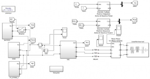
PI controller used in the proposed system for voltage regulation of SPVG, WTG, and ESS at DC PCC or at DC synchronization point with the proportional gain (Kpg) value 0.01 and integral gain (Kig) value 0.1. Controlling of PI controller on the ESS is charging the battery in buck mode, while generation is more than load demand and discharging the battery in boost mode if generation is less than the load demand, apart from the P & O MPPT control method for the SPVG system. Electrochemical energy storage (i.e., battery/ESS) is at 320V DC and its capacity is 2.08kWh (6.5Ah), DC/DC BDC inductor value is 2.5mH. Further, the common point DC is converted into 3-phase AC via VSC, then with an L filter (As per [29], calculated the L filter value for this proposed system, found and considered the L value 500μH i.e., 0.5mH is very much suitable for the harmonics mitigation and to maintain the THDs in limits) connected to the load (linear/non-linear). The developed simulation circuit of the proposed system is shown in Figure 3.
Figure 3. Simulation circuit of the proposed system
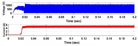
Figure 4. (a) Simulation results for SPVG output voltage and current, (b) WTG output 3-phase AC voltage (c) WTG output 3-phase AC current
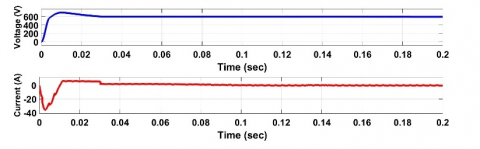
Figure 4 depicts the outputs of the SPVG and WTG systems. Figure 4 (a) describes the SPVG output voltage and current results, initially from 0 to 0.003 sec the voltage magnitude is gradually increased to 532V and the current magnitude is gradually reduced to 0 from 6.5A. Both voltage and current maintained their magnitudes steady after 0.003 sec. Respective magnitudes are indicated and therefore the maximum power (Pmax) generated from SPVG is 2.6 kW. Figure 4 (b) describes the WTG 3-phase ac output voltage magnitude is maintained under steady around 1kV, except very less time interval 0 to 0.02 sec in the beginning. Figure 4 (c) is of WTG 3-phase ac output current results and initially zero up to 0.02 sec.
Figure 5 results are of Wind system voltage and current at diode-bridge rectifier (as shown in Figure 1) output, some kinds of ripples are seen in the results. Wind AC 1,000V is converted to DC 253V with a rectifier. Further, steps up this voltage to a steady voltage of 600V DC via boost converter II and maintained its magnitude constant with the WTG capacitor (CWTG) - 400μF, these results are indicated in Figure 6. The SPVG gives 532V DC and steps up this voltage to 600V DC via boost converter I. The battery steps up the voltage from 320V to 600V via BDC. Boost converter I inductor (LSPVG) value is 3mH and Boost converter II inductor (LWTG) value is 12mH.
Figure 5. Rectified voltage and current of Diode-bridge Rectifier in Wind system
Figure 6. Simulation results of voltage and current at DC synchronization point, also the same results indicate, the output voltage and current of the boost converters at respective individual SPVG and WTG systems
Figure 6 indicates the simulation results of voltage and current at DC synchronization point / DC PCC and also the same results are nothing but, the output voltage and current of the boost converters at respective individual SPVG and WTG systems. The constant voltage fed from the two DPGs of boost converters with their respective capacitors CSPVG (SPVG capacitor) and CWTG to the DC PCC is maintained steady from 0.03 sec before that voltage is raised from 0 sec. In current magnitude, a very small ripple was observed during the steady condition. Finally, conclude that DC synchronization is made effectively.
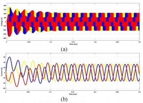
Figure 7. (a) Simulation results of VSC 3-phase AC voltage, (b) VSC 3-phase AC current, and the same point/results indicate before the filter insertion point
In Figure 7, voltage and current results are indicating the outputs considered before the filter point i.e., just the 3-phase AC outputs (voltage and current) of VSC, after the conversion of DC system to AC system via VSC. Initially, the voltage and current magnitudes are high for the first few secs, this may be considered a transient period and later their magnitudes are steady.
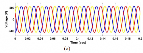
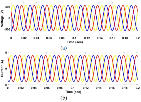
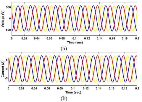
Figure 8. (a) Simulation results of Load Voltage (VL), (b) Load Current (IL) at 1kW load with filter
Figure 9. (a) Simulation results of $\mathrm{V}_{\mathrm{L}}$, (b) $\mathrm{I}_{\mathrm{L}}$ at 2kW load with filter
Figure 10. (a) Simulation results of VL, (b) IL at 3.5kW load with filter
The finest waveforms of load voltage and load current are presented for 1kW load after using the L-filter in Figure 8, and the maximum 3-phase AC load voltage is 565.68V i.e., the RMS value of load voltage (VRMS) is 399.99V, so VRMS is considered 400V. Further, 3-phase load voltage and load current results are presented for 2kW, and 3.5kW loads with filter in Figures 9, and 10 respectively. From the results, could observe the load current magnitudes are changed with respect to their load power demands as cited above. The above results indirectly indicate that the PCC of 3-phase VSC AC and 3- phase load points has been made successfully. Therefore, it can be concluded that the system is controlled (with the proposed controller) and balanced under various load power demands.
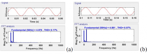
Figure 11. Harmonic spectra of R phase, $I_L$ at various time intervals without the filter
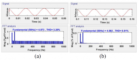
Figure 12. Harmonic spectra of Y phase, $I_L$ at various time intervals without the filter
Figure 13. Harmonic spectra of B phase, $I_L$ at various time intervals without the filter
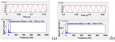
Figure 14. Harmonic spectra of R phase, $I_L$ at various time intervals with filter
Figure 15. Harmonic spectra of Y phase, $I_L$ at various time intervals with the filter
Figure 16. Harmonic spectra of B phase, $I_L$ at various time intervals with the filter
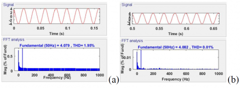
Load current THD results of the proposed system without filter and with filter are shown in Figures 11 to Figure 16. Figure 11,12 and 13 are dealing with the current THDs without the filter and Figure 14, 15, and 16 are dealing with the current THDs with the filter. In Figure 11, (a) indicates, that the current THD is 0.17% for the R phase with a time interval from 0 to 0.06 sec, and (b) indicates current THD is 0.97% for the R phase with a time interval from 0.1 to 0.16 sec, these values are without the filter. If considered the same phase with the filter, the current THDs are shown in Figure 14, (a) at the time interval 0 to 0.15 sec, the current THD is 0.19%, (b) at the time interval 0.5 to 0.65 sec, the current THD is 0.01%. Figure 12, (a) shows Y phase current THDs for the time interval 0 to 0.06 sec with 3.15% THD, and (b) indicates 0.1 to 0.16 sec time interval with 0.83% THD without the filter.
Figure 15, (a) shows for the same Y phase at the time interval of 0 to 0.15 sec, the current THD is 1.94% as well 0.5 to 0.65 sec time interval, current THD is 0.01% in (b). In the same manner, load current THDs for the B phase at various time intervals are presented. Therefore, it can be concluded from the above observation, that the current THDs are improved with filter i.e., harmonics are reduced in the proposed system.
The proposed Standalone Microgrid based on two DPG units; SPVG and variable speed WTG, has been found to function safely when constantly supplying load power demand at regulated voltage. PI controller is used in the proposed system of SPVG, WTG, and ESS for voltage regulation and DC synchronization. In the MPPT approach, the P & O method has been simply implemented in a simulation environment to attain high levels of performance from SPVA and without oscillations around MPP (Maximum Power Point). The ESS has only been used as a backup energy source, and its synchronization with the DC PCC has been accomplished successfully without causing system instability. Using an effective L filter, switching harmonics are effectively attenuated without losses. The finest results for the suggested system are shown and current THDs are within the limits, also presented. Hence, it represents the system is balanced. Finally, it is concluded that the proposed system, along with the controller employed in this study for SPVG-WTGBATTERY based SMG, may be used for ensuring reliable power supply in remote and isolated places, besides with reduced investment.
The above-proposed system is developed or limited capacity/rating and sufficient to meet the isolated low power demands with conventional controlled approaches. Future directions are to increase the above system of individual DPG capacities, besides some more DPGs introduced to the same system with advanced controlling/artificial intelligence techniques and with economic optimization for better results or a better-improved system to meet the isolated large area demands. So that, to increase the RESs utilization rate more.
|
a |
ideality factor of diode ≥ 1 |
|
b |
Boltzmann constant = 1.38 *10−23 J/K |
|
$\mathrm{E}_{\mathrm{go}}$ |
semiconductor energy bandgap=1.1 eV |
|
G |
solar irradiance = 1000 W/m2 |
|
$K_i$ |
$\mathrm{I}_{\mathrm{scs}}$ of SPVM at STC = 0.0032 |
|
q |
electron charge = 1.6*10−19 C |
|
$\mathrm{T}_{\mathrm{n}}$ |
nominal temperature (K) = 298 K |
|
$\mathrm{I}_{\mathrm{scs}}$ |
short circuit current, A |
|
T |
P-N junction temperature, K |
|
$\mathrm{N}_{\mathrm{s}}$ |
number of cells are connected in series |
|
V |
diode terminals voltage, V |
|
$\mathrm{V}_{\mathrm{ocs}}$ |
open circuit voltage, V |
|
DPG |
Dispersed Generation |
|
DG |
Distributed Generation |
|
SPVG |
Solar Photovoltaic Generation |
|
WTG |
Wind Turbine Generation |
|
WT |
Wind Turbine |
|
ESS |
Energy Storage System |
|
MPPT |
Maximum Power Point Tracking |
| SPVA | Solar Photovoltaic Array |
| SPVM | Solar Photovoltaic Module |
| SPV | Solar Photovoltaic |
| PV | Photovoltaic |
| P&O | Perturb and Observe |
ACRONYMS
|
BDC |
Bi-directional Converter |
|
DC |
Direct Current |
|
AC |
Alternating Current |
|
THD |
Total Harmonic Distortion |
|
L filter |
Inductance filter |
|
RES |
Renewable Energy Source |
|
SMG |
Standalone Microgrid |
|
PI |
Proportional-Integral |
|
MG |
Microgrid |
|
IM |
Islanded Mode |
|
PCC |
Point of Common Coupling |
|
VSC |
Voltage Source Converter |
|
IGBT |
Insulated Gate Bipolar Transistor |
|
$\mathrm{I}_{\mathrm{L}}$ |
Load current |
|
$\mathrm{V}_{\mathrm{L}}$ |
Load voltage |
[1] Keyhani, A., M. N. Marwali, and M. Dai (2009). Integration of Green and Renewable Energy in Electric Power Systems. Hoboken, NJ, USA: Wiley. http://dx.doi.org/10.1002/9780470556771
[2] Singh, B., and K. K. Bhalla (2015). Reduced converter topology for integrated wind and small-hydro energy generation system, IET Renew. Power Gener., vol. 9, no. 5, pp. 520529. http://dx.doi.org/10.1049/ietrpg. 2014.0235
[3] Guerrero, J. M., J. C. Vasquez, J. Matas, L. G. de Vicuna, and M. Castilla (2011). Hierarchical control of droopcontrolled AC and DC microgrids A general approach toward standardization, IEEE Trans. Ind. Electron., vol. 58, no. 1, pp. 158172. http://dx.doi.org/10.1109/TIE.2010.2066534
[4] Abessi, A., V. Vahidinasab, and M. S. Ghazizadeh (2016). Centralized support distributed voltage control by using end-users as reactive power support, IEEE Trans. Smart Grid, vol. 7, no. 1, pp. 178188. http://dx.doi.org/10.1109/TSG.2015.2410780
[5] Yang, K., and A. Walid (2013). Outage-storage tradeoff in frequency regulation for smart grid with renewables, IEEE Trans. Smart Grid, vol. 4, no. 1, pp. 245252. http://dx.doi.org/10.1109/TSG.2012.2232683
[6] Liu, B., F. Zhuo, Y. Zhu, and H. Yi (2015). System operation and energy management of a renewable energybased dc micro-grid for high penetration depth application, IEEE Trans. Smart Grid, vol. 6, no. 3, pp. 11471155. http://dx.doi.org/10.1109/TSG.2014.2374163
[7] Hamzeh, M., H. Karimi, and H. Mokhtari (2014). Harmonic and negative-sequence current control in an islanded multi-bus MV microgrid, IEEE Trans. Smart Grid, vol. 5, no. 1, pp. 167176. http://dx.doi.org/10.1109/TSG.2013.2263842
[8] Illindala, M., and G. Venkataramanan (2012). Frequency/sequence selective filters for power quality improvement in a microgrid, IEEE Trans. Smart Grid, vol. 3, no. 4, pp. 20392047. http://dx.doi.org/10.1109/TSG.2012.2197834
[9] Sun, Y., X. Hou, J. Yang, H. Han, M. Su, and J. M. Guerrero (2017). ” New perspectives on droop control in AC microgrid,” IEEE Trans. Ind. Electron., vol. 64, no. 7, pp. 5741-5745. http://dx.doi.org/10.1109/TIE.2017.2677328
[10] Shahparasti, M., M. Mohamadian, P. T. Baboli, and A. Yazdianp (2017). ” Toward power quality management in hybrid AC-DC microgrid using LTC-L utility-interactive inverter: Load voltage-grid current tradeoff,” IEEE Trans. Smart Grid, vol. 8, no. 2, pp. 857–867. http://dx.doi.org/10.1109/TSG.2015.2480717
[11] Miloud, R., A. Chandra, M. Tremblay, and H. Ibrahim (2018). ” Experimental implementation of an APC with enhanced MPPT for standalone solar photovoltaic based water pumping station,” IEEE Trans. Sustain. Energy, vol. 10, no. I, pp. 181-191.
[12] Tant, J., Geth, F., Six, D., Tant, P., Driesen, J. (2013). Multiobjective battery storage to improve PV integration in residential distribution grids. IEEE Transactions on Sustainable Energy, 4(1): 182191. http://dx.doi.org/10.1109/TSTE.2012.2211387
[13] Brekken, T.K.A., Yokochi, A., Jouanne, A.V., Yen, Z.Z., Hapke H.M., Halamay, D.A. (2011). Optimal energy storage sizing and control for wind power applications. IEEE Transactions on Sustainable Energy, 2(1): 6977. http://dx.doi.org/10.1109/TSTE.2010.2066294
[14] F Vivas, A. De Las Heras, F. Segura, and J. and jar (2018). ” A review of energy management strategies for renewable hybrid energy systems with hydrogen backup,” Renew. Sustain. Energy Rev., vol. 82, pp. 126-155. http://dx.doi.org/10.1016/j.rser.2017.09.014
[15] Alsaidan, I., A. Khodaei, and W. Gao (2016). Determination of battery energy storage technology and size for standalone microgrids, in Proc. IEEE Power Energy Soc. General Meeting, pp. 15. http://dx.doi.org/10.1109/PESGM.2016.7741385
[16] Datta, U., A. Kalam, and J. Shi (2020). Battery energy storage system control for mitigating PV penetration impact on primary frequency control and state-of-charge recovery, IEEE Trans. Sustain. Energy, vol. 11, no. 2, pp. 746757. http://dx.doi.org/10.1109/TSTE.2019.2904722
[17] Ongaro, F., S. Saggini, and P. Mattavelli (2012). Liion battery-supercapacitor hybrid storage system for a long lifetime, photovoltaic-based wireless sensor network, IEEE Trans. Power Syst., vol. 27, no. 9, pp. 39443952. http://dx.doi.org/10.1109/TPEL.2012.2189022
[18] Rodrguez, C. T., D. V. de la Fuente, G. Garcer, E. Figueres, and J. A. G. Moreno (2013). Recon-figurable control scheme for a PV microinverter working in both grid-connected and island modes, IEEE Trans. Ind. Electron., vol. 60, no. 4, pp. 15821595.
[19] Sreega R, Nithiyananthan K, Nandhini B. (2017). Design and development of automated solar panel cleaner and cooler. IJEEE 9: 186197.
[20] Rahul Wilson Kotla, Srinivasa Rao Yarlagadda (2020). Mathematical modeling of SPV array by considering the parasitic effects, SN Applied Sciences, 2(1), 50. doi:10.1007/s42452-019-1861-x.
[21] Vinod KR, Singh SK. (2018). Solar photovoltaic modeling and simulation: As a renewable energy solution. Energy Rep 4:701712. http://dx.doi.org/10.1016/j.egyr.2018.09.008
[22] Martina Calais, Trevor Pryor, Parisa Bahri (2011). ” Performance Evaluation, Simulation and Design Assessment of the 56 kWp Murdoch University Library Photovoltaic System”. ENG460 Engineering Thesis. P:17,18.
[23] Mao, M. Q., S. J. Yu, and J. H. Su (2003). Research on variable structure simulation modeling for wind-solar hybrid power systems, J. Syst. Simul., vol. 15, no. 3, pp. 361364.
[24] Zhou Tianpei and Wei Sun (2014). Optimization of Battery Supercapacitor Hybrid Energy Storage Station in Wind/Solar Generation System, IEEE Transactions on Sustainable Energy, vol. 5, no. 2. http://dx.doi.org/10.1109/TSTE.2013.2288804
[25] Shahram Fallah Faal, Alireza Sahab, Behnam Alizadeh (2023). Fuzzy-Reset Joint Controller Design for Robust Frequency Adjustment of Hybrid Microgrid including Fossil Fuel Systems, Photovoltaic, Fuel Cell and Energy Storage Systems. Journal of New Materials for Electrochemical Systems, Vol. 26, No.1, January 2023, pp.74- 82 https://doi.org/10.14447/jnmes.v26i1.a09
[26] Devineni Gireesh Kumar1, Neerudi Bhoopal, Aman Ganesh (2023). Implementation of an asymmetric multilevel inverter for solar photovoltaic applications using N-R approach. Journal of New Materials for Electrochemical Systems, Vol. 26, No.1, January 2023, pp.07-17 https://doi.org/10.14447/jnmes.v26i1.a02
[27] Rahul Wilson Kotla, Srinivasa Rao Yarlagadda (2021). Real-time Simulations on Ultracapacitor based UPQC for the Power Quality Improvement in the Microgrid. Journal of New Materials for Electrochemical Systems, Vol. 24, No.3, July 2021, pp.166-174 https://doi.org/10.14447/jnmes.v24i3.a04
[28] Hamza Bahri, Abdelghani Harrag, Hegazy Rezk (2022). Optimal configuration and techno-economic analysis of hybrid photovoltaic/PEM fuel cell power system. Journal of New Materials for Electrochemical Systems, Vol. 25, No.2, April 2022, pp.116-125 https://doi.org/10.14447/jnmes.v25i2.a05
[29] Aslan Mojallal, Saeed Lotfifard and Seyed Mohammad Azimi (2020), A Nonlinear Supplementary Controller for Transient Response Improvement of Distributed Generations in Micro-Grids, IEEE TRANSACTIONS ON SUSTAINABLE ENERGY, VOL. 11, NO. 1, JANUARY 2020 http://ieeexplore.ieee.org. Digital Object Identifier 10.1109/TSTE.2019.2895961
[30] Sainadh Singh Kshatri, Nagineni Venkata Sireesha, DSNM Rao (2023). Reliability Assessment of Hybrid Silicon- Silicon Carbide IGBT Implemented on an Inverter for Photo Voltaic Applications, Journal of New Materials for Electrochemical Systems Vol. 26, No.1, January 2023, pp.1-6 https://doi.org/10.14447/jnmes.v26i1.a01
[31] Li Fu, Xiuwei Fu, Ping Yang (2021). Maximum Power Point Tracking in Solar Cells with Power Quality Preservation Based on Impedance Matching Concept for Satellite Electrical Energy Supply, Journal of New Materials for Electrochemical Systems Vol. 24, No.2, April 2021, pp.111-119 https://doi.org/10.14447/jnmes.v24i2.a08
[32] Eric Nguwuo Petuenju† and Oumarou Savadogo (2016). Characterization of CuInS2 Thin Films Grown by Transducer-based Ultrasonic Spray Pyrolysis for PV Solar Cells Applications, Journal of New Materials for Electrochemical Systems 19, 169-179 (2016).
[33] S.M. Duron-Torres, L.E. Villagrana-Munoz, V.M. Garcia-Saldivar (2010). Estimation of the Hydrogen Flux from a PEM Electrolyzer, based in the Solar Irradiation Measured in Zacatecas Mexico. Journal of New Materials for Electrochemical Systems 13, 235-238 (2010).