Narendra Kumar Muthukuri* | Subbarao Mopidevi
© 2023 IIETA. This article is published by IIETA and is licensed under the CC BY 4.0 license (http://creativecommons.org/licenses/by/4.0/).
OPEN ACCESS
This paper prompt fifteen level packed U cell (PUC) based multilevel-inverter (MLI) topology for standalone and grid-connected applications. The 15PUC required only eight IGBTs compared with other conventional MLIs (FC, NPC, HCHB and CHB). This paper describes and proposes a sensorless proportional resonant (SLPR) controller with radical multicarrier (RMC) based LS PD-PWM and a novel switching algorithm. These proposed controllers compensate for DC-link capacitor voltages, control third, higher and zeroorder harmonics. The stability analysis and robustness of the proposed SLPR controller with the PUC system have been verified through Bode and Nyquist plots. In addition, the 15PUC system is proving highly efficient-based system through power loss analysis. The effectiveness and performance of 15PUC with proposed controllers are evaluated by using experimentally and MATLAB simulations also. The results are verified through FFT analysis and obtained THD% comes under the IEEE-519 standard.
PUC packed U cell, MLI multilevel inverter, SLPRC sensorless proportional resonant controller, PD phase disposition, THD total harmonic distortion, MI modulation index
Nowadays MLIs are the classiest electric power conversion devices, power and other industrial sectors adopting MLIs for a lower range to higher range power applications [1-2]. MLIs are offered to control higher-order harmonics for linear to nonlinear loads under the IEEE-519 standard at the lower switching frequency.
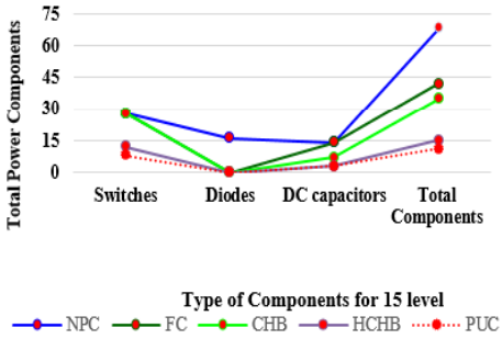
In the last decade, conventional MLIs are difficult to meat some unambiguous features. Like as, higher efficiency, low switching losses, voltage balancing problems, higher complexity level, control of higher-order harmonics and difficulty operating to work at lower switch frequency. The most predefined conventional MLIs are (I) CHB MLI topology is proposed by Peng et al. (II) FC MLI topology is proposed by Meynard et al. (III) NPC MLI topology is proposed by Nabae et al [3]. Researchers are identified asymmetrical MLIs owned as such unambiguous features, PUC topology in one of the high efficient topology compared with latest to other conventional MLIs [4-7]. Most researchers are investigating crucially about power loss analysis for getting higher efficiency. Majorly power loss analysis, the functioning power semiconductor components have been a high priority. The power losses of MLIs include conduction ON state to OFF state losses, switching losses and gate driver losses. For off-state conditions, PSCs produce small current leakages, mostly researchers are not consider small current leakages. For these reasons, power analysis of any type of power converters is considered nearly an approximation of conduction to switching losses. So authors investigate to mitigate power losses by using SPWM techniques and other non-linear controllers also. So researchers identify, that PUC MLI topology is the best methodology compared with other conventional to latest MLIs. PUC topology is owned lower switching and conduction losses, lower harmonics, precious quality outputs and develop more levels by using fewer PSC. The following Fig.1 consists required PSC for PUC and other conventional 15 level MLI topologies. For 15 level, PUC contains 8 IGBTs and 3 DC source or DC link capacitors (11 components only).
Figure 1. Semiconductor components for 15-level MLIs
Most of the researchers established PUC, conventional to the latest and other MLI topologies are controlled through hysteresis, PI, and linear controllers [8-10]. Mostly, these linear controllers face a bunch of problems. Like as, voltage balancing and sensing problems, steady-state and dynamic errors, bandwidth errors and also sluggard response of the system due to system sudden changes. Then, the authors defeated those drawbacks with help of SPRC (sensorless PR controller). The sensorless controller develops transient output without source feedback sensors and compensates for DC-link capacitor voltages. Also, the SPR controller mitigates third and zero-order harmonics [11-14]. This paper mainly focused on the SPR controller with a novel switching sequence of 15PUC MLI by using modified level shift PD based PWM [15-16].
The following sections are represents 15PUC MLI organizations [2] describes switching algorithm and modelling of 15PUC, [3] represents RMC based level shift PD PWM, section [4] represents SLPR voltage integrated into algorithm and PWM, section [5] represents stability analysis of 15PUC MLI, [6] represents simulation results, section [7] represents Experimental results, section [8] represents power loss analysis and [9 & 10] sections represents conclusion and references.
Novel switching controlling algorithm, all PSC are triggered simultaneously compared with conventional switching. Mostly, (13-14) and (2-3) switching modes are opposite modes compared with conventional switching algorithms. In 15PUC MLI, its consists of 8 IGBT switches ( (S1 to S8). From those 8 PSC, 4 IGBT switches S1,3,5,7 are acted as normal switches and another 4 IGBT switches S2,4,6,8 act as complementary switches. The source voltage of 15PUC MLI is based on the following equation 1 .
V1V2=37,V2V3=3 (1)
From equation 1, DC source voltages are considered as
V1=230VV,V2=99 V,V3=33 V
The output voltage equation of 15PUC MLI is
Vae=Vab+Vbc+Vcd+Vde (2)
From the 2nd equation, all node voltage (a, b, c, d) equations are present below
Vae=(S1−1)V1+(1−S3)(V1−V2)+(V2−V3)(1−S5)+(1−S7)V3Vae=(S1−S3)V1+(S3−S5)V2+(S5−S7)V3 (3)
Now apply KVL for load of 15PUC
Vl=Vae−ilRl−Lldildt (4)
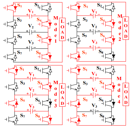
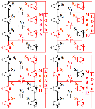
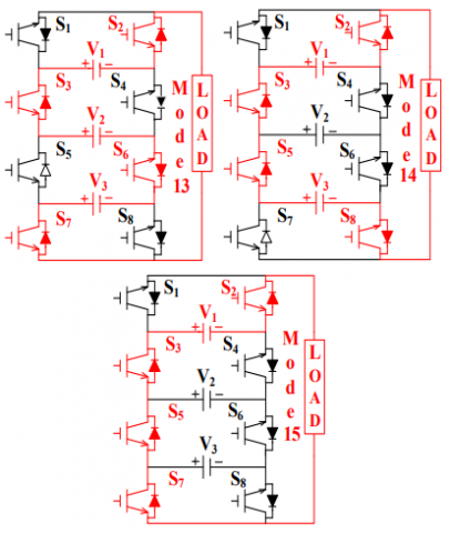
From novel controlling switching algorithm contains 15 conduction modes of operations; all operating modes are presented in Figure.3 (a to d). The voltage stress of 8 IGBT switches of 15 conduction modes is presented in Figure 2.
Figure 2. Voltage stress on 8 IGBT switches of 15PUC
Figure 3a. Switching Algorithm for one to four modes
Figure 3b. Switching Algorithm for five to eight modes
Figure 3c. Switching Algorithm for nine to twelve modes
Figure 3d. Switching Algorithm for thirteen to fifteen modes
The controlling of MLI topologies through several closed and open loop controllers. In this paper sensorless PR controller is fetched with RMC based PD PWM. Because of, that controller system controls complexity and improve the efficiency of 15PUCMLI. For 15 level, PD based SPWM method 14 MC are considered only. All 14 MC are constrained constant frequency, 00 phase shift along with constant amplitude range. The ultra-transient pulses develop through reference wave is touched along with 14 MCs. From 14 MCs, every TC to TC maintains 0 to 0.01 seconds only in the RMC PD SPWM method. Probably, LS MC based PD SPWM gives the best lower-order harmonic results compared with several LS based SPWM controllers. Following Figure.4. Represents RMC based LS PD SPWM.
Figure 4. RMC based level shift PD-SPWM
For 15PUC MLI, (Nc number of MCs = Number of output voltage levels -1)
NC=NL−1 (5)
where, NL= Number of output voltage levels &NC= Number of MCs
For SPWM controllers, lower-order harmonics with perfect output voltage levels of any kind of MLIs are based on the MI (modulation index) of the system.
MIinv=AmAC∗Nc (6)
Where Ac is the amplitude of MC signal & Am is the amplitude of reference waveform
Following Figure 5 represents increment to decrement switching angels for positive half cycles of 15PUC. These waveforms indicate every peak-to-peak voltages with peak-topeak increment and decrement firing angels.
Figure 5. Switching Angels of 15PUC MLI
For every peak to peak voltage of 15PUC is V1p=V7=2307= 32.85≅33
The time period of every level to level width is T1p=T15= 0.0006666s
For a positive half cycle, firing angels of every level-level is considered as θ1a=180015=120
For Fourier series, the fundamental steeped 15 level voltage waveform is
v(wt)=4Vdcπ{(cosα1+cosα2+cosα3+⋯)sinwt+(cos3α1+cos3α2+2cos3α3+⋯)sin3wt3+(cos5α1+2cos5α2+2cos5α3+⋯)sin5wt5+⋯⋯}→7
For positive half of the cycle, firing angels of 7 step to step voltage levels are considered as
α1<α2<α3<α4<α5<α6<α7<π2
The odd-order harmonics of 15PUC (3rd, 5th, 7th, 9th, 11th, 13th, and 15th) are controlled through RMC LS based PD PWM.
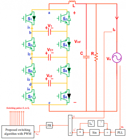
For 15PUC MLI contains, 8 unique switching pulses are implemented through a novel switching algorithm. For all modes, sine waveform (Vsin_ref ) travels along with all required (Cr1 to Cr14) carriers. The sine wave travels along a positive axis, all positive voltage levels are activated. The sine wave travels along a negative axis, all negative voltage levels are activated. Whether sudden load changes, conventional controllers are problematically maintain constant capacitor voltages with voltage sensing problems. To defeat these problems, 15PUC MLI is controlled through an SLPR controller. Figure. 6 indicates the SLPR controller for smartgrid systems.
Figure 6. SLPR controller for grid-connected systems
Especially, the amplitude is controlled predominantly by using an SLPR controller and required phase shifting signals are transferred to the grid or other load requirements. The measured grid voltage angel is fetched with PLL block to maintain proper phase shift signals by using sin block. For efficient controlling of system power, sin block is accumulated with maximum i∗m reference current. From Figure.6, comparison current results is&i∗s are fetching with PR controller. After that, unique switching pulses are implemented through SPWM technique into the path of getting PR controller signals. These switching pulses help to prevent the inverter from higher-order harmonics for constant to high frequency based systems. Afterwards, 15PUC MLI is energetically applicable for any linear to nonlinear oriented grid based systems.
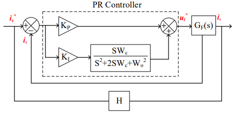
Mostly for grid and industrial usages, LCR filter is added with SLPR controller for 15PUC MLI. The LCR filter is mitigate transient and steady-state errors and ripple content in output waveforms. Also, the LCR circuit helps with the extraction of reference phase shift angels to SPWM systems. Measurement of L & C parameters is based on switching frequencies only, here Δv change in voltage is considered as 5%. The block diagram of PR controller is shown below in Figure.7. WO and WC are resonant and gain crossover frequencies. H represents system output feedback fetch with SL systems.
Figure 7. PR controller Block diagram
The TF of LCR filter and PR controllers is
GPR(S)=KP+KI∗WCSS2+2WCS+W2o (8)
The output and input of filter is represented as shown below
VO=RCSR+RCS=RRcS+1 and Vi=SL+RRcS+1
Then, the TF of the LCR controller is
GLCR=RS2RLC+SL+R (9)
The selection of L & C values depends on switching frequency.
L=Vpeak (n−1)∗Fswitching ∗ΔvC=12π∗Fswitching
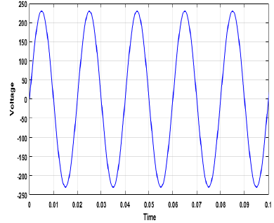
The charge and discharging paths of DC capacitors are based on novel switching algorithm with an SLPR controller, and all paths of DC capacitors are shown in Figure.8. For 15, 8 & 1 modes, an accomplishment of capacitors are nominal state. For 14 & 2 modes, C2 is exploited as charging state and C1 is exploit as no effect. For 4th mode, C2 is exploited as no effect and C1 is exploit as charging state. For 11 & 5 modes, C2 is exploit as no effect and C1 is exploit as discharging state. For 9 & 7 modes, C2 is exploit as discharging state and C1 is exploit as no effect. For 13 & 3 modes, DC capacitors are exploit as charging mode and also DC capacitors are exploit as discharging mode at 10 and 6 modes.
Figure 8. 15PUC fundamental waveform
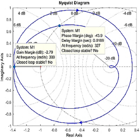
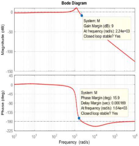
For development of study state outputs for industrial and other smart grid applications, 15PUC MLI is controlled through SLPR voltage controller with LCR filter circuits. The 15PUC gives efficient results without an LCR filter circuit for household and standalone applications. Here, 15PUC is controlled through SLPR controlling system, then the stability of system is verified by using bode and Nyquist plots concerning phase and gain margins. Following Figures.9-10 represent stability plots for without and with SLPR controller. By using without an SLPR controller, stability of the system is unstable because of negative marginal results (Gm is -2.79 and Pm is −43.9∘) from both bode to Nyquist plots. By using SLPR controller, stability of the system is stable because of positive phase marginal results (Gm is 9 dB and Pm is 15.9∘) from both enriched bode to Nyquist plots. Also, SPPR controller is an extremely stabilized system. Because phase marginal outputs are higher than gain marginal outputs, and both phase and gain margins are positive levels.
Figure 9. Bode and Nyquist Plots of without PR controller
Figure 10. Bode and Nyquist Plots of SLPR controller
The following comparison table 1 indicates for Nyquist and bode plots based on without and with SLPR controller.
Table 1. Stability for without and with SLPR controller
|
Type |
Bode & Nyquist Plots |
Stability |
|
|
Phase margin |
Gain margin |
||
|
Without SLPR controller |
-43.9 |
-2.79 |
Un Stable |
|
With SLPR controller |
15.9 |
9 |
Stable |
The 15PUC MLI is realized with hardware and MATLAB/Simulink circumstances by using SLPR controller. The 15 PUC results are verified standalone mode for both linear and non-linear load applications and also verify grid applications. Following table 2 contains load parameters for 15PUC MLI.
Table 2. 15PUC MLI Load parameters
|
Parameters |
Specifications |
|
DC (Vdc) source Voltage |
V1=230, V2=99, V3=33 |
|
Switching Frequency |
3 KHz |
|
Fundamental Frequency |
50 Hz |
|
Load Parameters |
R = 40 Ω; R1 & L1 = 40 Ω & 300 mH R2 L2 = 100 Ω 200 mH |
|
LCR FILTER VALUES |
|
|
C |
53 µF |
|
L |
110 mH |
|
WO |
314.5 |
|
WC |
3 kHz |
|
KI |
0.1 |
|
KP |
30 |
Mode 1: Standalone mode applications
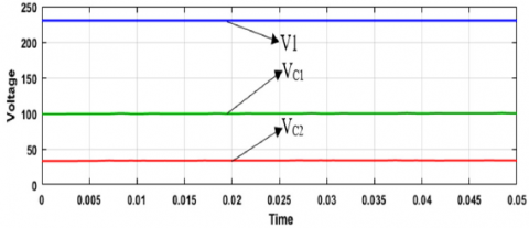
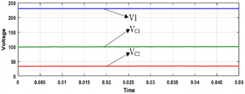
The performance and effectiveness of 15PUC MLI topology is controlled with different loads, such as linear and non-linear loads. Figure 11 represents source voltages of 15PUC. It illustrates that, VC2 capacitor is preserved 33 V and another VCl capacitor is preserve at 99 V only and also V1 voltage is 230 V.
Figure 11. Source and Capacitor Voltages
Mode 1. RL Load 40 Ω & 300 mH
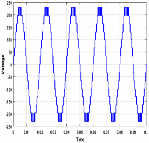
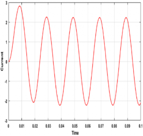
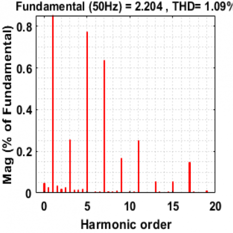
The RL load current and voltage output waveforms of 15PUC are presented in Figure 12 (a&b). For standalone applications, SLPR controllers mitigate higher-order harmonics under IEEE-519 standard, results are developed by without LCR filter design. Following Figures. 12 (c&d) are represents harmonical outputs (3.70% & 1.09%) for load voltage and current outputs.
Figure 12(a). 15PUC Load Voltage
Figure 12(b). 15PUC Load
Figure 12(c). Voltage THD
Figure 12(d). Current THD
Mode 2: Line regulation of 15PUC outputs by using HW rectifier:
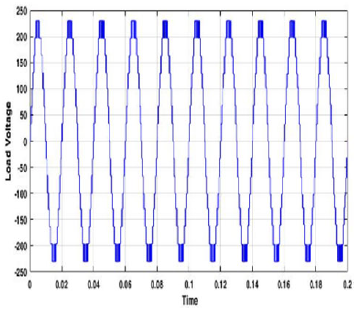
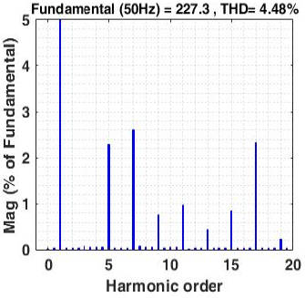
In this mode, single phase HW rectifier and RL loads are connected with 15PUC MLI topology. Frome line regulation, following Figures.13. (a&b) is output voltage and current waveforms for 15PUC. From Figures.13b, sudden step changes in load at 0.2 to 0.4ms is verified by dotted lines at load current waveforms. Mostly, 0.01ms required for stabilization of load current outputs due to sudden load changes. In this section PR controller maintain constant output voltages due to corresponding sudden load changes. Also, provide transient outputs for non-linear loads. For line regulation, SLPR controllers mitigates higher-order harmonics under the IEEE-519 standard, results are developed without filter. Following Figures. 13 (c&d) are represents harmonical outputs (4.48% & 1.61%) for load voltage and current outputs. Table 3 represents mitigated harmonics for both load voltage and current outputs.
Figure 13(a). 15PUC Load voltage
Figure 13(b). 15PUC Step Load current
Figure 13(c). Voltage THD
Figure 13(d). Current THD
Table 3. 15PUC Load harmonics for linear-nonlinear loads
|
TYPE |
Load Voltage |
Load Current |
|
RL Load (40 Ω 300 mH) |
3.70% |
1.09% |
|
HW Rectifier (40 Ω, 50 mH) |
4.48% |
1.61% |
Mode 2: Grid-connected applications
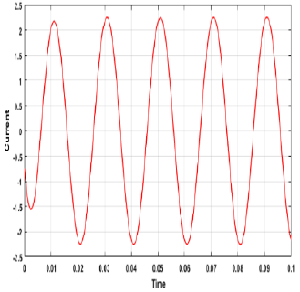
For Grid-connected applications, 15PUC and PR controller is associated with LCR filter circuits. Figure.6. represents 15PUC MLI for grid applications. Here, 15PUC MLI is injecting reactive and active powers to grid usages with maintain constant PF between 0.6 to 0.8. Figure.14. represents source voltages of 15PUC for grid usages. It illustrates, SLPR controller automatically compensates VC1,2 capacitor Voltages. Grid current and outputs results are presented in Figure.15. (a&b). The current harmonics of 15PUC is 0.04%, LCR filter is highly impacted and support with SLPR controller for encountering on third and zero order harmonics. Following Figure.15c. Represent mitigated grid current harmonics under the IEEE-519 standard.
Figure 14. Source and Capacitor Voltages
Figure 15(a). 15PUC Grid Voltage
Figure 15(b). 15PUC Grid current
Figure 15(c). THD for Grid current
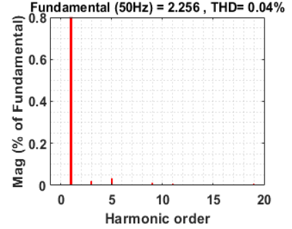
The downscale prototype version of 15PUC is shown in Figure.16. It was developed in VFSTR laboratory and performance is validated with closed loop and PDPWM control. The MPC board on each eight IGBTs FGA15N120ANTD, eight TLP250 optocouplers, one 7840 voltage sensing circuit, and two 4081 buffer circuits are approaching to develop an approximate proposed structure. The prototype version load is applicable up to (≤ 500 watts) only, it is tested under standalone condition by using RL load (200 Ω, 400 mH) and remaining all parameters are same in Table.4. Following table.4 represents comparison of experimental and simulated load current and voltage harmonics for standalone applications through RL load only.
Table 4. Experimental vs Simulation Results
|
TYPE |
Experimental Results |
Simulation Results |
|
Load Voltage |
7.788% |
3.70% |
|
Load Current |
8.387% |
1.09% |
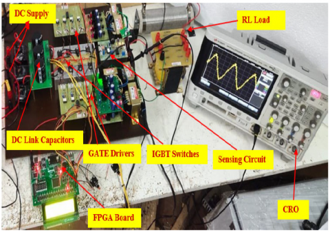
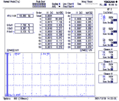
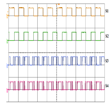
In this prototype, 15PUC controlled through FPGA controller. Sensing circuit help to fetch the feedback signals and controller generate PWM signals with help of sensing circuit. Generating pulses are fetch with drier circuit. Load voltage and load current waveforms of 15PUC is presented at Figure.17. The both load voltage and current (7.78%, 8.387%) harmonics are observed by using power quality analyser, they are shown in Figure.18. Also, switching pulses are presented at Figure.19 (a&b). From Figure.19a contains one to four IGBTs switching pulses, two and four switching pulses are act as complementary pulses for one and three IGBTs. From Figure.19b contains five to eight IGBTs switching pulses, six and eight switching pulses are act as complementary pulses five and seven IGBTs.
Figure 16. Experimental annotated photograph
Figure 17. Practical Load voltage and current outputs (200V/Division)
Figure 18. THD for Load voltage and currents
Figure 19(a). 1 to 4 IGBTs Pulses
Figure 19(b). 5 to 8 IGBTs pulses
The PSC are play a key role while power conversions through converters. The power converters are principally facing different power losses, they are switching losses, conduction losses, diode reverse recovery losses, gate driver losses and, diode off state losses. Mainly in power loss analysis, gate driver losses and diode off-state losses are neglected due to very low power losses. The conduction losses are appearing during switches on state condition, following equation is used to calculate conduction losses in MLIs.
PCL=1T∫T0(VF+RONiF)iFdt (15)
Where VF and iF represents forward voltage drop in ON state and mean value of passing current through devises. ON state resistance indicate RON, T represents time period of frequency. After that switching losses are play most significant in power loss analysis. These losses are appeared during ONOFF state and OFF-ON state conditions on semiconductor components. Here, neglecting diodes losses due to idealness diode. However, for all IGBTs switching losses calculations, diode reverse recovery losses, IGBTs turn OFF and IGBTs turn ON losses are considered. The following equation is help to enumerate all switching losses.
PSL=1T∑nj=1[EOFF−IGBT+EOFF−IGBT+Errl] (16)
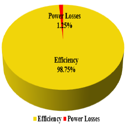
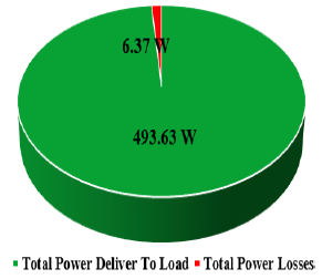
Here, T represents the time period for operating frequency, the number of transitions represents through n. Errl represents reverse recovery losses on energy demand, EOFF−IGBT represents turn OFF energy demand and EON−IGBT represents turn ON energy demand. So mostly, all power losses are calculated by using 7 and 8 equations. Following pie chart Figures.20 and 21 represents efficiency versus power losses and maximum delivered power to load versus total power losses in 15PUC MLI. Figure.22 represents efficiency versus modulation index.
Figure 20. Efficiency V/S Power losses
Figure 21. Deliver Power V/S Power losses
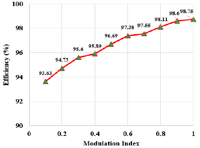
Figure 22. Efficiency V/S Modulation Index Plot for 15PUC
In any MLIs family, modulation index is varying at 1 to 0.1, after that THD rapidly increases. Similarly, the efficiency of the system is very low at lower modulation indexes. In the power losses calculation procedure, source voltage, load parameters, switching frequencies are involved. For controlling power losses, higher switching frequencies are eliminated and maintain lower switching frequencies are only.
In this work, authors realized performance of 15PUC MLI based on SLPR controller with novel switching algorithm. The proposed 15PUC has fewer PSC for higher levels. The RMC based LS PD PWM fetched with the proposed SLPR controller; these controllers improve the transient response of the system and automatically compensate for DC link capacitor voltages without voltage sensors from the source side. In addition, these controllers eradicate switching stress, and zero to third-order harmonics by using a novel algorithm.
The authors declare that they have no conflict of interest and no acknowledgement of this paper.
|
MLI |
Multilevel Inverter PUC-15 |
|
PUC-15 |
Packed U Cell 15 Level |
|
SPWM |
Sinusoidal Pulse Width Modulation |
|
LS |
Level Shift |
|
PD |
Phase Disposition |
|
THD |
Total Harmonic Distortion |
|
EMI |
Electromagnetic Interference |
|
SPRC |
Sensorless Proportional Resonant Controller PSC |
| PSC | Power Semiconductor Components |
|
PR |
Proportional Resonant |
|
Ar, Ac |
Amplitude of Reference & Carrier Signals Wc, Wo |
|
Wc, Wo |
Gain Crossover & Resonant Frequency |
|
NC |
Number of Capacitors or Number of Source Voltages |
|
NSW |
Number of Switches |
[1] Franquelo, L.G., Rodriguez, J., Leon, J.I., Kouro, S., Portillo, R. and Prats, M.A.M. (2008) ‘The age of multilevel converters arrives’, IEEE Industrial Electronics Magazine, Vol. 2, No. 2, pp.28–39: https://doi.org/10.1109/MIE.2008.923519
[2] M. Vijeh, M. Rezanejad, E. Samadaei and K. Bertilsson, "A General Review of Multilevel Inverters Based on Main Submodules: Structural Point of View," in IEEE Transactions on Power Electronics, vol. 34, no. 10, pp. 9479-9502, Oct. 2019: https://doi.org/10.1109/TPEL.2018.2890649
[3] K. Corzine, Y. Familiant, "A new cascaded multilevel Hbridge drive", IEEE Trans. Power Electron., vol. 17, no. 1, pp. 125-131, Jan. 2002: https://doi.org/10.1109/63.988678
[4] E. Samadaei, A. Sheikholeslami, S. Gholamian, J. Adabi, "A square T-type (ST-type) module for asymmetrical multilevel inverters", IEEE Trans. Power Electron., vol. 33, no. 2, pp. 987-996, Feb. 2018: https://doi.org/10.1109/TPEL.2017.2675381
[5] Y. Ounejjar, K. Al-Haddad and L. Gregoire, "Packed U Cells Multilevel Converter Topology: Theoretical Study and Experimental Validation," in IEEE Transactions on Industrial Electronics, vol. 58, no. 4, pp. 1294-1306, April 2011: https://doi.org/10.1109/TIE.2010.2050412
[6] Narasipuram, R.P. and Yadlapalli, R.T. (2019) ‘Performance analysis and design optimisation of 3-Ø Packed U Cell inverter for industrial drive applications’, Int. J. Mathematical Modelling and Numerical Optimisation, Vol. 9, No. 3, pp.309–337: http://dx.doi.org/10.1504/IJMMNO.2019.10020920
[7] Narendra kumar muthukuri, Rajanand Patnaik Narsipuram, Subbarao mopidevi, “Optimization of total harmonic distortion using carrier based PWM techniques for nested multilevel inverter topologies”, Int. J. Industrial Electronics and Drives, Vol. 5, No. 2, 2020: https://doi.org/10.1504/IJIED.2020.115575
[8] M. Tariq, M. Meraj, A. Azeem, A. I. Maswood, A. Iqbal and B. Chokkalingam, "Evaluation of level-shifted and phase-shifted PWM schemes for seven level single-phase packed U cell inverter," in CPSS Transactions on Power Electronics and Applications, vol. 3, no. 3, pp. 232-242, Sept.2018:https://doi.org/10.24295/CPSSTPEA.2018.00 023
[9] Y. Ounejjar and K. Al-Haddad, "Fourteen-band hysteresis controller of the fifteen-level packed U cells converter," IECON 2010 - 36th Annual Conference on IEEE Industrial Electronics Society, Glendale, AZ, 2010, pp.475-480: https://doi.org/10.1109/IECON.2010.5674922
[10] Hani vahedi, philippe-alexandre labbe, kamal al-haddad, “sensor-less five-level packed U-cell (PUC5) inverter operating in standalone and grid-connected modes”, IEEE transactions on industrial informatics, vol.12, no.1, august 2016: https://doi.org/10.1109/TII.2015.2491260
[11] Mostafa abarzadeh, hani vahedi, kamal al-haddad, “ fast sensor less voltage balancing and capacitor size reduction in PUC5 converter using novel modulation method”, IEEE transactions on industrial informatics, vol.15, no.8, august 2019: https://doi.org/10.1109/TII.2019.2893739
[12] Ningyun zhang,Houjun tang and chen Yao, “A symmetric method for designing a PR controller and active damping of the LCL filter for single phase grid connected PV inverters”, Energies 2014, 7, 3934-3954; doi:10.3390/en7063934.
[13] P.A. Salodkar, P.S. Kularni, Manoj A. Waghmare, P.C. Cgaturvedi & Sandeep N, “asymmetric H-bridge single phase seven level inverter topology with proportional resonant controller”, IETE journal of research, 06 dec2017: https://doi.org/10.1080/03772063.2017.1396934
[14] Narendra kumar muthukuri, subbarao mopidevi, “A Novel Switching Sequence for Asymmetrical 15-Level Packed U Cell Inverter Topology with Improved Total Harmonic Distortion”, journal of control automation and electrical systems, 2021(32), pp.721-734: https://doi.org/10.1007/s40313-021-00689-x
[15] Narendra kumar muthukuri, subbarao mopidevi, “ Analysis of a modified switching pattern for packed U cell-15 inverter topology with advanced level shift carrier pulse width modulation techniques”, Electrica 2021; 21(2): 272-282: https://doi.org/10.5152/electrica.2021.20082
[16] Narendra Kumar muthukuri, Ravindranath Tagore Yadlapalli, “Comparison of carrier based PWM technique for Active Neutral Point Clamping Multilevel Inverter”, International Conference on Intelligent Computing and Control Systems (ICICCS 2020) ISBN: 978-1-7281-4876-2: https://doi.org/10.1109/ICSTSN53084.2022.9761358
[17] Narendra kumar muthukuri, subbarao mopidevi, “Optimal Controller Design of PUC-15 MLI Topology for Smart Grid Applications with Reduced Power Components”, 2022 International Conference on Smart Technologies and Systems for Next Generation Computing (ICSTSN) 978-1-6654-2111-9/22/$: https://doi.org/10.1109/ICICCS48265.2020.9121130