Nadheer M. Mohammed* | Yasir M. Ameen | Basil M. Saied
© 2026 The authors. This article is published by IIETA and is licensed under the CC BY 4.0 license (http://creativecommons.org/licenses/by/4.0/).
OPEN ACCESS
This paper presents a new grid-connected hybrid photovoltaic (PV)-battery topology employing an LLC resonant converter (LLC-RC) as the PV-side converter and a CLLLC resonant converter (CLLLC-RC) for battery charging/discharging. The key problem to be solved is the significant overshoot of current and power that is experienced while switching from one operation mode to another in fast-changing PV irradiation and battery power direction cases. During such situations, the battery energy storage system (BESS) has to play an active role in supporting the DC bus by either absorbing excess PV power or supplying the shortage of power due to PV power changes. The main task is to balance the power in two directions, which is crucial for stabilizing the DC link voltage. Three control methods for the battery side are considered: a conventional proportional-integral (PI) controller, a dual PI controller in parallel, and a frequency prediction controller. An approach for dual-PI controller design with a synchronized output of the voltage and current control loops is introduced. In addition, an adaptive cycle-by-cycle current limit method is used to avoid transition overcurrents without disrupting the normal operation of the converter. A predictive frequency controller is also designed in order to determine the optimal value of switching frequency according to the battery current prediction results. The proposed hybrid PV-battery-grid system was simulated in MATLAB/Simulink software using five practical operating modes corresponding to different PV generation, battery charging, battery discharging, and power flow through the grid conditions. The proposed hybrid PV-battery-grid system realized zero-voltage switching (ZVS) in both power flow directions, efficiency higher than 97%, grid-current total harmonic distortion (THD) lower than 5%, and power factor more than 0.99. The suggested dual-loop parallel controller with simultaneous operation of voltage and current regulators outperformed traditional dual-loop approaches in terms of dynamics. The designed model predictive control (MPC) additionally increased the system performance, providing a settling time equal to 30 ms using only two tuning parameters and no additional hardware as well as minimum current distortion. Nevertheless, the proposed coordinated dual-PI controller along with the adaptive cycle-by-cycle current limiter provided the best transient performance during mode transitions. These conclusions are established by simulation; experimental verification is ongoing work.
hybrid PV-battery system, LLC-resonant converter, CLLLC-resonant converter, dual-loop control strategy, multi-mode energy management, model predictive control, maximum power point tracking
The rapid transition to a low-carbon energy system has significantly accelerated the rate at which renewable energy technologies, such as photovoltaic (PV) systems, are adopted. The installation of global PV capacity has increased exponentially over the past decade as a result of its modular structure, cost-effectiveness, and environmental friendliness. However, there are some challenges posed by the inherent variability of solar energy concerning grid management, voltage regulation, and performance. Variations in solar irradiance affect PV output, thus creating some challenges in performance and grid quality. Among the challenges posed by this kind of variable source in the utility grid is maintaining the stability of the DC bus voltage [1-3].
To solve the above problems, a battery energy storage system (BESS) has been integrated into PV generation systems to provide energy buffering, peak shaving, and load balancing. The efficiency of PV-BESS systems depends mainly on the performance of power electronic converters that act as interfaces between energy sources, BESS, and the utility grid. In this context, traditionally used hard-switched converters have inherent drawbacks related to high switching losses, high voltage/current stresses on semiconductor components, increased electromagnetic interference, and more heat generation due to increased switching frequency. As a result, resonant topologies like the LLC resonant converter (LLC-RC) and CLLLC resonant converter (CLLLC-RC) have drawn much interest because they possess zero-voltage switching (ZVS) and zero-current switching. Therefore, much effort has been exerted lately to design and control LLC-RC converters for PV applications. A few different control approaches for power regulation of LLC and bidirectional CLLLC-RC have been studied. Classical proportional-integral (PI) control is still popular due to its simplicity and easy implementation. Nonetheless, the gains of the classical PI controllers are always tuned for a certain nominal point with respect to fixed parameters of the converter and stable input/output/load conditions. Considering that the dynamics of the resonant converters are nonlinear and heavily dependent on the operating point, changes in the voltage ratio, load, state of the battery, and parameters of the resonant tank will considerably change the behavior of the plant. As a result, the PI controller with fixed gains is no longer able to ensure the necessary bandwidth and damping throughout the whole range of operation. Therefore, retuning of gains or use of other techniques is needed to provide stable dynamic behavior under the changed conditions. Jean-Pierre et al. [4] used a region-based control strategy utilizing an enhanced incremental conductance maximum power point tracking (MPPT) algorithm, mode discrimination, cascaded voltage–current PI loops, and frequency variation control for bidirectional LLC converters. But fixed-gain PI controllers may fail to ensure similar performance in a wide range of operation, and the effect of mode switching on DC-bus voltage stability has not been considered. The research [5] demonstrated an 11-kW bidirectional CLLC converter working at 73 kHz with different controllers for constant current CC and constant voltage CV operation modes. The output signal of the smaller one was used to control the voltage-controlled oscillator (VCO), providing automatic switching between the two controllers. The problem is that the controllers were developed for specific conditions and no research was conducted on the interplay of the two controllers and its effect on current overshoot and DC bus stability. Nkembi et al. [6] suggested a droop-based feedforward strategy for CC-CV operation with a cascaded controller for the Dual Active Bridge (DAB) battery charger. The new control strategy decreased the CC and CV switching time from about 4 ms to 1.5 ms and ensured suppression of voltage/current dips. Nevertheless, this work is limited to the CC-CV charge transition and was verified by numerical simulations only. Wen et al. [7] replaced PI control with model predictive control (MPC) in a bidirectional CLLLC circuit in an effort to enhance dynamic performance and retuning. Better accuracy and fast dynamic response were demonstrated in the process. Yet the direct MPC control of switching frequency in CLLLC circuit and its effectiveness at different operating modes were not considered. Also, the computational complexity of MPC grows with the number of possible control actions considered in every sampling instant [8, 9]. The bidirectional resonant converters are widely used in the hybrid PV-battery grid-tie systems to control the two-directional energy transfer between the battery, DC bus, and power line. Despite great progress in control techniques, no dedicated protection methods for these devices have been developed yet. The literature is focused on efficiency, soft-switching and disturbance rejection, while the transient overcurrent phenomena have not been investigated yet. Thus, the cycle-by-cycle current limitation technique is needed to prevent peak currents and minimize stress on semiconductors. Yang et al. [10] investigated three overcurrent protection techniques for LLC-RC, which include increasing frequency, hybrid frequency-PWM control, and clamping diodes. Nevertheless, the paper focused on the LLC circuit in one direction only, neglecting the CLLC/CLLLC conversion in both directions during rapid mode transitions. Zaikin [11] introduced two methods of short-circuit protection for LLC-RC, where the resonant-tank current estimation is based on the indirect voltage measurement of the capacitor or inductor voltage. Despite the successful implementation and experimental verification, the paper focused on LLC operation only and neglected the CLLC/CLLLC bidirectional operations during rapid mode transitions. Yang et al. [12] suggested a method for optimization of parameters of the CLLLC-based inductive power transfer system in order to decrease coil current under pad misalignment conditions while keeping the output current constant regardless of the load value. There are still several significant constraints that have to be mentioned, though. The majority of research works on converter topologies and control approaches deal with each of these issues separately, and bidirectional CLLLC-RC systems are generally controlled through single-loop control strategies or mode-dependent strategies. Even though soft-switching is a crucial requirement for minimization of switching losses and semiconductor stresses, it does not guarantee transient stability itself. The aspects of DC-bus offset, current overshoots, and recovery time gain additional importance during fast power flow and mode changes. In addition, there are few works on comprehensive investigations of the considered five operation modes. In order to overcome such limitations, the control design approach is carried out systematically, starting from traditional PI controller design, then proceeding to a dual loop controller design for simultaneous control of DC-bus voltage and battery current, and lastly, frequency-based control for better transient performance and less tuning requirement for controller. The operation of multimode energy management algorithm is designed to manage five different operating modes, including PV operation, battery charge/discharge operation, and grid interaction. Moreover, a cycle-by-cycle current limiter is designed to avoid any transient battery current overshoot.
The key highlights of the study can thus be described as below:
•Hybrid PV-battery power system using LLC-RC topology along with the bidirectional CLLLC-RC.
•Proposed is a coordinated dual-loop control scheme for the bidirectional CLLLC converter. While existing techniques have used the same PI controller for voltage/current control purposes, the proposed approach utilizes both voltage and current PI controllers at the same time to control the DC-bus voltage and battery current. Controller tuning has been done in order to coordinate both loops, minimize current overshoot, decrease deviation from the desired DC-bus voltage and fasten response during charging and discharging operations.
•Analysis is performed on the five operational modes using classical PI, double PI and model-predictive controllers. Comparison of system operation is also made with and without the proposed cycle-by-cycle current limiter to assess transient overshoot and stability.
•A comprehensive simulation-based comparison is conducted to evaluate the proposed system architecture, control strategies, and transient performance.
•Performance validation through quantitative measures to prove high efficiency levels and low total harmonic distortion (THD) values.
•A cycle-by-cycle hardware-assisted current limiter technique to avoid current overshoot in different modes.
The scope of the present work is the design, coordination, and comparative evaluation of these control and protection strategies through detailed time-domain simulation; experimental validation is outside the present scope and is addressed as future work.
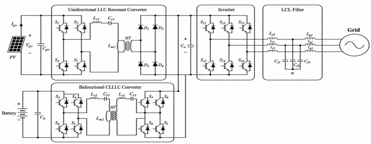
Figure 1 depicts the architecture of the proposed system. The following are some of the key innovations of the proposed system: its unique topology, dual PI control, multivariable mode operation, predictive control technique, and transient current limitation scheme described in the preceding section.
Figure 1. Block diagram of the proposed grid-connected hybrid PV-battery energy system
In particular, the PV array is interfaced with the common DC-link through a full-bridge LLC-RC, where the switching frequency is calculated according to the MPPT-based pulse frequency modulation (PFM) control. For the proposed structure, the PV side controller controls the PV power extraction and generates the switching frequency of the LLC-RC. Moreover, the BESS is interfaced with the common DC-link through a full-bridge CLLLC-RC, allowing for bidirectional energy flow both in charging and discharging modes for the battery. In particular, the performance analysis of the battery-side converter is carried out with the above control techniques. In particular, the above control signal is given to the frequency generation block, and then, after some calculations, the switching frequency of the battery-side CLLLC-RC is generated. The common DC-link is interfaced with the distribution network through a three-phase voltage-source inverter with LCL filtering. On the other hand, the phase-locked loop (PLL) algorithm is utilized to keep synchronized with the grid in the grid-side controller, and the synchronous dq-axis control of the grid-side active and reactive power flow is carried out. This section introduces the power flow coordination algorithm, PV side controller design, and three different types of controllers used for the battery side converter. BESS are coupled with PV generation systems in order to store excess energy generated from solar sources and deliver it when the generation capacity is not enough. Power available at the DC bus is defined as follows in Eq. (1).
$P_{D C}=P_{P V}+P_{ {bat }}-P_{{grid }}$ (1)
where, $P_{P V}, P_{ {bat }}$, and $P_{ {grid }}$ are the PV , battery, and grid-side powers, respectively.
Power electronic converters form the critical interface between PV arrays, energy storage systems, and the utility grid. Traditional hard-switching DC–DC converters experience considerable switching losses when operating at high frequencies. The instantaneous switching power loss in a MOSFET can be approximated as in Eq. (2).
$P_{s w}=\frac{1}{2} \times V_{D S} \times I_D \times\left(t_r+t_f\right) \times f_s$ (2)
where, $V_{D S}$ is drain-source voltage, $I_D$ is drain current, $t_r$ and $t_f$ are rise and fall times, $f_s$ is switching frequency.
2.1 Photovoltaic array
The PV array is the main energy provider of the proposed hybrid system, whose purpose is the conversion of solar energy into electrical energy. Due to the nonlinear behavior of the PV array and the impact of external parameters on it, precise modeling of the PV array becomes highly significant.
The PV module’s output power is dictated by the basic formula given below in Eq. (3).
$P_{P V}=V_{P V} \times I_{P V}=\eta \times G \times A_{P V}$ (3)
where, $\eta$ is module efficiency, $G$ is solar irradiance (W/m²), $A_{P V}$ is the array area (m²).
This strong dependence on irradiance G creates power imbalances in grid-connected systems.
Table 1 provides details of the major electrical parameters of the hybrid PV-battery energy system.
Table 1. Main specifications of the proposed system
|
Parameter |
Value |
|
PV Rated Power |
126.1 kW |
|
PV Voltage Range |
700–1000 V |
|
DC Bus Voltage |
700–800 V |
|
Battery Voltage (Fully Charged) |
699 V |
|
Battery Capacity |
180 kWh |
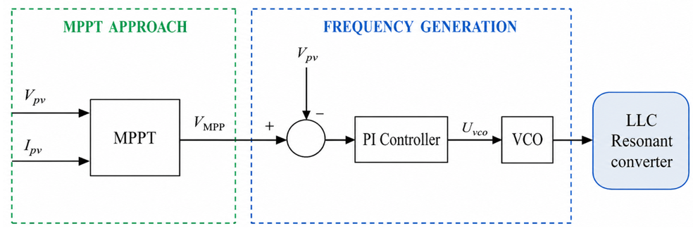
In order to ensure that the maximum amount of energy is harvested from the PV array depending on varying conditions of irradiance and temperature, the point of operation keeps changing using the MPPT algorithm. The output of this algorithm is used to generate the switching frequency signal for the PV side LLC-RC converter, as shown in Figure 2.
Figure 2. Maximum power point tracking (MPPT) PFM control using voltage-controlled oscillator (VCO) implementation in LLC resonant converter at PV side
The PV operating point is tracked using the perturb-and-observe MPPT algorithm. The resulting normalized control voltage drives the VCO and determines the LLC switching frequency, as formulated in the following subsection.
2.2 Steady-state analysis and resonant tank design of the LLC-RC
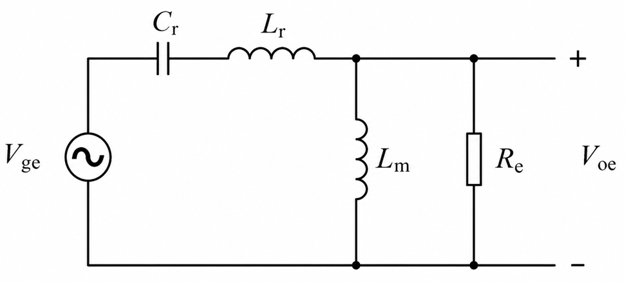
LLC-RC has two resonant frequencies. First, the resonant frequency $f_{r_1}$ can be calculated based on resonant inductor $c_{r}$ and resonant capacitor $f_{r_2}$ using Eq. (4) below. Second, the resonant frequency $f_{r_2}$ depends on $L_{r}$, $C_{r}$ and magnetizing inductance $L_{m}$ using the relation provided in Eq. (5). DC voltage gain of the LLC resonant converter can be found using fundamental harmonic approximation (FHA) [13, 14] using Eq. (6) below.
Figure 3 represents the linear AC model of the LLC resonant converter.
Figure 3. Linear AC equivalent circuit model of the LLC-RC based on fundamental harmonic approximation
$f_{r 1}=\frac{1}{2 \pi \sqrt{L_r C_r}}$ (4)
$f_{r 2}=\frac{1}{2 \pi \sqrt{\left(L_r+L_m\right) C_r}}$ (5)
${Gain}(G)=\frac{n * V_{o e}}{V_{g e}}=\frac{s L_m / / R e}{\frac{1}{s C r}+s L r+s L_m / / R e}$ (6)
where,
$n$ is the transformer ratio,
$V_{g e}$ is equivalent input voltage,
$ V_{o e}$ is equivalent output voltage.
The quality factor Q is defined in Eq. (7), it represents the system’s ability to store energy, and mathematically, it is expressed as:
$Q=\frac{X_L}{R_e}=\frac{X_c}{R_e}$ (7)
Re: Reflected resistance represents the reflection of the output load through the transformer to the input side and is mathematically represented in Eq. (8)
$R_e=\frac{8}{\pi^2} \times n^2 \times Rout$ (8)
The inductance ratio can be expressed as in Eq. (9)
$m=\frac{L_r+L_m}{L_r}$ (9)
where,
$L_r$ is the resonant inductor,
$L_m$ is the magnetizing transformer inductance,
$c_r$ is the resonant capacitor of HFPT.
Therefore, when the power is transferred from input source $V_{ge}$ to output $V_{oe}$ , it is named as forward power transfer, and the gain is expressed as Eq. (10)
$G=\frac{1}{\sqrt{\left(1+\frac{1}{m}\left(1-\frac{1}{f_x^2}\right)\right)^2+\left(f_x-\frac{1}{f_x}\right)^2 Q^2}}$ (10)
where, $F_x$ is the normalised frequency and it is expressed as in Eq. (11)
$F_x=\frac{f_s}{f_r}$ (11)
where,
$f_s$ is the switching frequency,
$f_r$ is the resonant frequency.
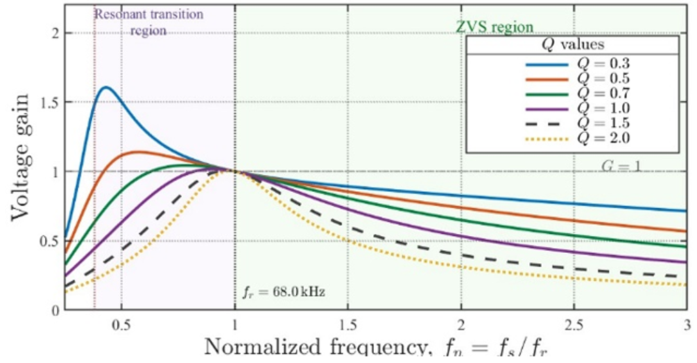
So, the point of gain will move according to operating conditions, but it will be near the resonant frequency at which it is selected in the proposed design. The gain is a function of the inductance ratio (m), the quality factor (Q) and the normalised frequency ($F_x$) as shown in Figure 4.
Based on the required gain and the coordination between the normalized frequency and the gain illustrated in Figure 4, the inductance ratio is selected as 6.9, while the quality factor is set to 1 (Q = 1).
Since no voltage step-up or step-down is required, the converter is mainly utilized for galvanic isolation and integration with the resonant tank. Therefore, the high-frequency power transformer (HFPT) turns ratio is selected to be unity (1:1), which means that n = 1.
Parameters of the optimum LLC-RC used in connecting the PV array to the common DC link are stated in Table 2. The resonant inductor, magnetizing inductor, and the value of the resonant capacitor have been selected such that they ensure soft switching throughout the operating range, along with being efficient and having a wide ZVS capability. Frequency control-based power regulation becomes efficient due to the switching frequency ranging from 50 kHz to 100 kHz; efficient frequency control-based power regulation becomes possible using the MPPT controller.
Figure 4. Normalized voltage gains characteristics of the LLC-RC for different quality factor (Q) values at inductance ratio m = 6.9
Table 2. Design parameters of the LLC-RC
|
Parameter |
Value |
|
Resonant Inductance (Lr) |
9.6287 µH |
|
Magnetizing Inductance (Lm) |
56.9 µH |
|
Resonant Capacitance (Cr) |
0.569 µF |
|
First Resonant Frequency |
68 kHz |
|
Switching Frequency |
50-100 kHz |
|
Inductance Ratio (m) |
6.9 |
|
Quality Factor (Q) |
1 |
The LLC-RC is a key component in the proposed scheme, as it ensures efficient and high-frequency switching of power from the solar panel to the DC link. By virtue of its controlled-frequency operation, it becomes possible to synchronize it with the MPPT operation for optimal power capture. The adoption of resonant conversion makes the system highly efficient and reliable.
2.3 Steady-state analysis and resonant tank design of the bidirectional CLLLC-RC
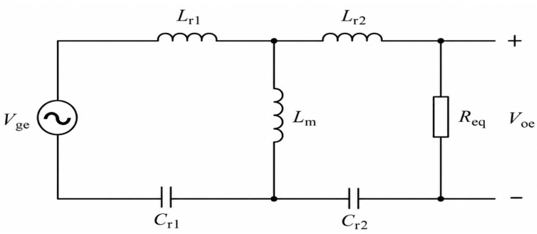
The FHA equivalent circuit of the bidirectional CLLLC-RC is shown in Figure 5.
Figure 5. Linear AC equivalent circuit model of the CLLLC-RC based on fundamental harmonic approximation
In contrast to other converters, CLLLC-RC converter can achieve symmetrical operation in both directions of power flow.
With regard to the bidirectional CLLLC-RC converter based on the basic harmonic approximation, two symmetrical resonant tanks at the two opposite sides will ensure identical soft-switching performance in both directions of power flow. For the symmetrical bidirectional CLLLC converter, the secondary-side resonant elements are referred to the primary side through the transformer turns ratio n = N_p/N_s. The symmetry conditions are expressed as [15]:
$L_{r 1}=n^2 L_{r 2}$ (12)
$C_{x 2}=n^2 C_{x 1}$ (13)
Accordingly, the referred secondary-side resonant parameters become identical to the primary-side parameters:
$L_{r 2}^{\prime}=n^2 L_{r 2}=L_{r 1}, \quad C_{r 2}^{\prime}=\frac{C_{r 2}}{n^2}=C_{r 1}$ (14)
This equivalence enables the converter to exhibit similar resonant and soft-switching characteristics in both power-flow directions. The characteristic impedance of the referred symmetrical resonant tank is defined as
$Z_r=\sqrt{\frac{L_{r 1}}{C_{r 1}}}$ (15)
The primary-side series resonant impedance at the switching frequency is
$Z_{r 1}\left(j \omega_s\right)=j \omega_s L_{r 1}+\frac{1}{j \omega_s C_{r 1}}$ (16)
For completeness, the secondary-side series resonant impedance and its value referred to the primary side are
$Z_{r 2}\left(j \omega_s\right)=j \omega_s L_{r 2}+\frac{1}{j \omega_s C_{r 2}}$ (17)
$Z_{r 2}^{\prime}\left(j \omega_s\right)=n^2 Z_{r 2}\left(j \omega_s\right)$ (18)
For battery energy storage applications, the CLLLC-RC regulates the battery charging current $I_{bat}$. The average charging current in the resonant mode is related to the converter parameters by Eq. (19).
$I_{b a t}=\frac{8}{\pi^2} \times \frac{n \times V_{D C}}{2 \times Z_r}$ (19)
where, $n$ is the transformer turns ratio, $ V_{D C}$ is the DC bus voltage, $Z_r$ is the tank impedance at resonance. The above equations lay down the theoretical basis for the proposed system design presented below. Table 3 below presents the parameters of the bidirectional CLLLC-RC used as the battery interface. The design of the resonant tank is symmetric in nature to enable soft-switching bidirectional power flow in both charging and discharging modes. The values of the resonant inductor, magnetizing inductor, and capacitor are designed to provide optimum resonance over the resonant frequency range from 25-50 kHz. The values of the above parameters make possible the efficient integration of batteries into the proposed system.
Table 3. Design parameters of the CLLLC-RC
|
Parameter |
Value |
|
Resonant Inductance (Lr) |
5.08 µH |
|
Magnetizing Inductance (Lm) |
14.48 µH |
|
Resonant Capacitance (Cr) |
2000 nF |
|
Resonant Frequency |
50 kHz |
|
Switching Frequency |
25-60 kHz |
|
Inductance Ratio (m) |
3.85 |
|
Quality Factor (Q) |
0.42 |
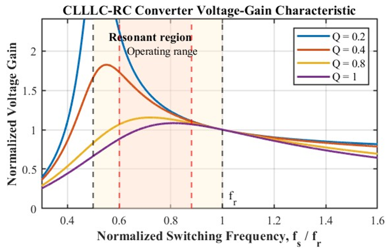
Figure 6. Normalized voltage gain characteristics of the CLLLC-RC for different quality factor (Q) values at inductance ratio m = 3.85
One of the most vital elements in the proposed hybrid system is the CLLLC-RC because it enables the transfer of power effectively between the battery and the DC buses. The stability of the operation of the converter at any moment and quick response can be achieved owing to the symmetrical nature of the design and dual-loop control strategy in a stable manner at any time and provide rapid dynamic responses with maximum efficiency.
Figure 6 shows the normalized voltage gain characteristic of the designed CLLLC-RC converter. The frequency at which the switching occurs is chosen based on the design of the resonant tank and is normalized with respect to the second resonant frequency. The shaded area denotes the resonance operating region between the two resonances where the converter can control the voltage gain with the needed resonant properties. The operating region lies within this shaded area, which helps to maintain soft-switching operations. Design parameters for the converter are summarized in Table 3.
2.4 Battery mathematical model
The BESS is a crucial part of the hybrid PV battery architecture design, offering services like energy storage, load levelling, and power flow control in both directions. Through the BESS, the system can operate effectively in response to the variability in solar radiation and changing load conditions.
For system-level analysis, the battery is modelled using a Thevenin equivalent circuit, consisting of:
$V_{ {bat }}=V_{ {oc }}-I_{ {bat }} R_b$ (20)
where,
$V_{ {bat }}$ = battery terminal voltage,
$I_{ {bat }}$ = battery current (positive for discharging, negative for charging).
The State of Charge (SOC) represents the available energy in the battery and is a key parameter for control and energy management, as given in Eq. (21).
${SOC}(t)={SOC}\left(t_0\right)-\frac{1}{C_{ {bat }}} \int_{t_0}^t I_{ {bat }}(t) d t$ (21)
where,
$C_{ {bat }}$ = battery capacity in ampere hour (Ah).
2.5 Control strategies of the bidirectional CLLLC-RC
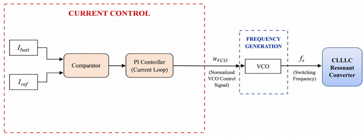
The conventional bidirectional current-control scheme regulates the battery current during both charging and discharging, as shown in Figure 7.
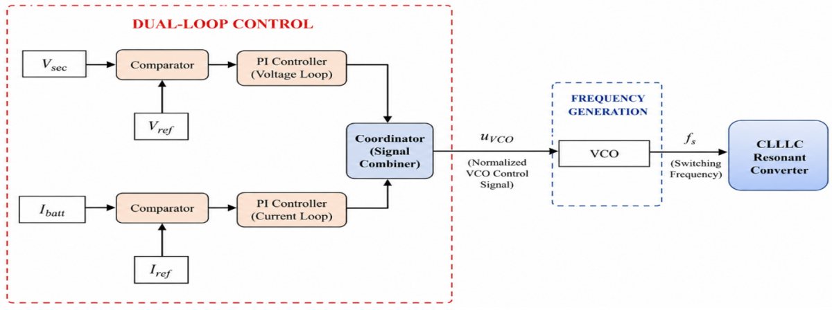
One disadvantage of using the traditional bidirectional PI controller is that it controls only the battery current during charging and discharging but does not control the secondary-side voltage directly. Therefore, the voltage control and the switch over to constant voltage mode have not been considered. In order to counteract this problem, the proposed coordinated dual-loop PI controller is such that it uses both current and voltage control loops to enable the control of battery current as well as the secondary-side voltage. The dual-loop controller is the major control technique used in this case, especially the bidirectional CLLLC-RC. This enables control of the dc bus voltage and battery currents simultaneously for proper system performance in both charge and discharge modes. Figure 8 shows the structure of the bidirectional CLLLC-RC control technique.
Figure 7. Block diagram of the conventional bidirectional current PI control
Figure 8. Block diagram of the dual-loop controller in bidirectional CLLLC-RC
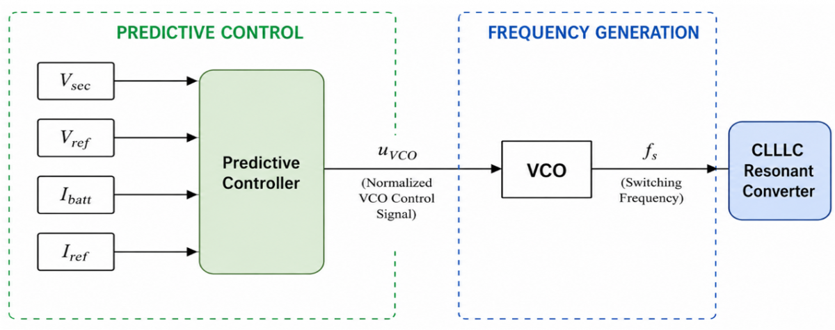
Vsec and Ibatt denote the measured secondary-side voltage and battery current, respectively, while Vref and Iref are their corresponding reference values. The coordinated controller output uVCO represents the normalized control signal applied to the VCO, which generates the switching frequency fs of the CLLLC-RC. The VCO maps the normalized control signal uVCO into the switching frequency fs, according to the frequency range determined from the FHA-based converter design. Traditional CC-CV charge controllers are based on separate control schemes for current and voltage regulation. However, a mismatch in controller design due to mode change can cause a discontinuous control process resulting in current overshooting [16]. In a CLLLC-based battery charger, such a disturbance is likely to affect the DC-bus voltage as well. As a solution for the above-discussed problem, the voltage and current-loop control signals are integrated to create one unified VCO input. Unlike the traditional MIN-selector that enables only the more constraining control loop, in this case, both loops can be active at the same time to generate the frequency control signal. When tuned properly, the dual-loop controller will control battery current and secondary-side voltage, providing a smoother control process and better transient dynamics. Table 4. Comparison of the conventional MIN-selector and the proposed summation-based dual-loop control architectures. Comparison of the structural and dynamic characteristics of the traditional minimum selector (MIN-selector)-based CC-CV control and proposed dual-loop control architecture.
Table 4. Comparison of conventional and proposed dual-loop PI control architectures
|
Property |
Conventional MIN-Selector [5] |
Proposed Summation Architecture |
|
VCO input |
min (uᵥ, uᵢ) |
uᵥ + uᵢ |
|
Active loops |
One loop at a time |
Both loops simultaneously |
|
CC-CV transition |
Abrupt mode switching |
Continuous signal summation |
|
Control basis |
Minimum-command selection |
Linear time-invariant (LTI) signal superposition |
|
Transition overshoot |
High [5, 16] |
Reduced by coordinated summation |
|
Anti-windup |
Inactive-loop integrator |
Applied to both loops |
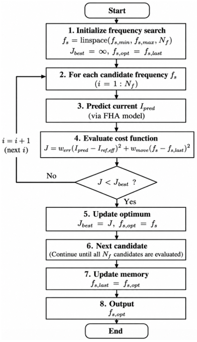
The five parameters of the dual-loop scheme were tuned sequentially. The current loop was tuned first, with the voltage loop disabled and the frequency command constrained to the inductive region of Figure 6 to preserve ZVS; the voltage loop was then tuned one decade lower in bandwidth so that both commands superpose at the VCO input without interaction; and Klim was set to the smallest value suppressing the transition overshoot without activating in steady state. The predictive controller instead requires only the two cost-function weights, trading offline tuning effort for online computation. To provide a comprehensive comparison of the control performance, with particular emphasis on transition stability, a predictive frequency-control strategy is additionally evaluated, whose block diagram is shown in Figure 9. Although predictive control offers fast dynamic response, its full-system implementation may impose considerable computational burden and control complexity [17]. Therefore, the predictive strategy is not applied to the entire conversion system. Instead, it is restricted to the bidirectional CLLLC-RC, where the switching frequency is selected directly as the control output. This frequency-only predictive formulation reduces the number of optimized variables and online calculations while preserving the main dynamic benefits of predictive control, particularly during operating-mode transitions. Figure 10 presents the operation flowchart of the proposed MPC algorithm, highlighting the main computational steps during each control cycle.
Figure 9. Block diagram of the frequency predictive control strategy for the bidirectional CLLLC-RC
Figure 10. Operational flowchart of the proposed MPC algorithm
In every control interval, the predictive control method initiates the frequency selection procedure, calculates a set of finite switching frequencies, determines the battery current for each of these candidate frequencies by using the FHA model, and formulates the cost function incorporating both the error of current tracking and the cost associated with changing frequency. The candidate that results in the smallest cost function value is taken to be the optimal switching frequency and is saved into memory for the next control interval. Symbols used in Figure 10 are defined in Table 5.
Table 5. Nomenclature of symbols used in the model predictive control (MPC) algorithm flowchart (Figure 10)
|
Symbol |
Definition |
|
$I_{ {pred }}$ |
Predicted battery current |
|
$I_{{ref,eff}}$ |
Effective current reference |
|
$f_s$ |
Candidate switching frequency |
|
$f_{ {s,last }}$ |
Switching frequency applied in the previous control interval |
|
$f_{ {s, opt }}$ |
Optimal switching frequency selected by the predictive controller |
|
$N_f$ |
Number of candidate frequencies |
|
$J$ |
Cost function |
|
$I_{{best }}$ |
Minimum cost obtained during the current search |
|
$w_{ {err }}$ |
Weighting factor of the current-tracking error term |
|
$w_{ {move }}$ |
Weighting factor of the frequency-movement penalty term |
The computational complexity of the formulation may be directly calculated using the algorithm depicted in Figure 10. For every control cycle, the 40 candidate switching frequencies are examined. Given that the candidate set is predefined during the design process, all quantities depending only on the switching frequency, such as the reactances of the resonant tank, the magnitude of the equivalent impedance and the prediction coefficient, are constant and can be calculated once prior to the controller implementation by filling up the look-up arrays, whose memory size amounts to 320 bytes. The online calculation for each candidate thus requires only two multiplication, one subtraction, one squaring and one comparison operation in single precision floating point arithmetic, without requiring any division, square-root or exponentiation operation. The whole process is completed within about 3.5 µs on an STM32G474 (Cortex-M4F, 170 MHz) and 2.0 µs on a TMS320F28379D processor, which is below 20 % of the switching period at the maximum operating frequency. The frequency-only formulation is therefore suitable for per-cycle operation on general digital control hardware, unlike finite-control-set predictive control methods, where the number of calculated switching combinations increases with the prediction horizon.
2.6 Grid-side inverter and LCL filter design
Lastly, the controlled DC-link voltage is connected to the grid via a three-phase voltage source inverter (VSI) along with an LCL filter. The inverter makes use of a sinusoidal pulse width modulation (SPWM)-based synchronous reference frame control technique to control active and reactive powers [18], while the LCL filter eliminates the switching harmonics and ensures good quality grid currents at the point of common coupling (PCC). In the grid-assisted battery charging mode, the bi-directional VSI acts as an active pulse width modulation (PWM) rectifier controlling the DC-link power while taking a near sinusoidal grid current at unity power factor. The LCL filter applied at the grid interface is responsible for the elimination of harmonics [19]. The harmonic attenuation ratio at frequency $f_h$ is Eq. (22). Design specifications of the grid-side inverter and LCL filter are tabulated in Table 6.
$\left|H_{L C L}\left(f_h\right)\right|=\frac{1}{\left|1-\left(L_1+L_2\right) \times C \times\left(2 \pi f_h\right)^2\right|}$ (22)
where, $L_1$ is the inverter-side inductance, $L_2$ is the grid-side inductance, $C$ is the filter capacitance.
Table 6. Grid-side inverter and LCL filter specifications
|
Inverter Switching Frequency |
10 kHz |
|
LCL Filter Inductance (L1) |
550 µH |
|
LCL Filter Capacitance (C) |
126 µF |
|
LCL Filter Inductance (L2) |
20 µH |
|
Grid Voltage |
400 V |
|
Operating Modes |
5 Modes |
Five distinct operating modes characterize system behaviour under varying solar irradiance conditions. Table 7 provides a summary of all five operating modes with their key parameters.
Table 7. Summary of the five operating modes. Ambient temperature is 45 ℃ in all modes
|
Mode |
Time (s) |
Irradiance (W/m²) |
Battery Current |
PV Status |
Description |
|
1 |
0.0–0.2 |
1000 |
0 A (idle) |
Active |
PV supplies grid |
|
2 |
0.2–0.4 |
600 |
+120 A (discharge) |
Active |
PV + battery supply grid |
|
3 |
0.4–0.5 |
0 |
+120 A (discharge) |
Inactive |
Battery supplies grid |
|
4 |
0.5–0.7 |
600 |
−120 A (charge) |
Active |
PV + grid charge battery |
|
5 |
0.7–0.9 |
750 |
−113 A (charge) |
Active |
PV charges battery |
Figure 11. Operating mode transition sequence of the proposed hybrid PV-battery system with different irradiance levels
The five modes of operation of the suggested PV-battery system are illustrated in Figure 11 based on different levels of irradiance. When the irradiance level is high during the day time, the PV arrays feed the grid independently, whereas battery feeds the grid in addition to PV arrays when the irradiance level falls down. In zero irradiance level, only battery feeds the grid. During charging mode, battery is fed either through PV arrays and grid or purely through excess power from PV arrays. Such modes of operation confirm two-way operation of power and control of DC-link voltage. Modes of operations are specified by solar irradiance and battery currents in Table 7. The PV output is controlled by available maximum power, while battery current is chosen as per the load demand.
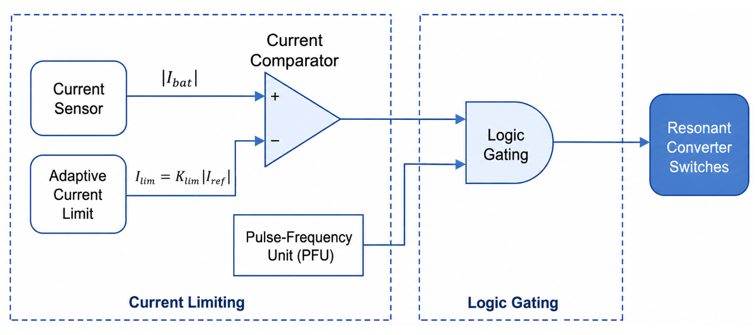
This paper proposes a hardware based current limiting method for transient improvement and mode transition of grid connected hybrid PV Battery systems with resonant converter. Though there have been several studies on grid connected resonant converters, only limited works have focused on how to protect the power switch from potential current surges during their transitional stages. The proposed current limiting method consists of a fast-comparing unit and a logic gate controller to control the current cycle-by-cycle.
The proposed cycle-by-cycle current-limiting mechanism compares the measured battery current with an adaptive threshold defined as:
$I_{{lim }}=K_{ {lim }}\left|I_{{ref }}\right|$ (23)
where,
$I_{{lim }}$ is an adaptive current limit,
$K_{ {lim }}$ is current limiting coefficient.
Under normal conditions, the comparator output enables the switching pulses generated by the pulse-frequency unit. When
$\left|I_{ {bat }}\right|>I_{ {lim }}$
The logic gate suppresses the corresponding switching pulse. Once the current returns below the prescribed limit, normal pulse transmission is restored. This hardware-assisted action operates at the switching-cycle level and provides fast overcurrent intervention without modifying the primary control structure. As can be seen in Figure 12, the proposed technique monitors the battery current and then compares the value with that provided by the adaptive limit. If the current value exceeds the threshold previously defined, then there will be inhibition of switching pulses for temporary duration. The end product will be current restriction cycle-by-cycle.
Figure 12. Proposed adaptive hardware-assisted cycle-by-cycle current limiting scheme for smooth mode transition and converter protection
Unlike the existing techniques, the proposed technique uses hardware-assisted current restriction technique that restricts current cycle-by-cycle without any effect on the main control technique. Existing techniques only solve the problem of overcurrent protection during the occurrence of fault conditions or overload or transition of power using control-based approaches but not current.
The proposed technique utilizes current regulation during normal operations, especially during mode transition because of overshoot and oscillations during mode transition periods. The proposed technique uses an adaptive current comparator along with a logic gate.
Furthermore, while conventional research works are generally limited to single converter systems, the suggested approach targets implementation within a grid connected hybrid PV-battery system with various operating modes. Apart from offering improved transient performance, such a setup will make it possible to enhance the integration process, thanks to the reduced need for abrupt power input during mode changeover.
As a result, the suggested approach offers not only current limitation, smooth transition between modes and system stability, which represents an important improvement over the existing technologies. Hardware-based methods for current reduction during transition include negative temperature coefficient thermistor (NTC) inrush current limiters, current-limiting resistors and pre-charge systems. Although all of these approaches manage to significantly reduce the level of current spikes, they depend on extra passive elements or switches. The proposed adaptive cycle-by-cycle current limiter provides transient overcurrent suppression through switching action without using any additional pre-charge circuitry.
The limiter of Figure 12 was modelled using an ideal comparator and an ideal logic gate. In a physical implementation, the sensing, comparison, gating, and gate-drive stages
together introduce a propagation delay of the order of 150–200 ns for commercially available fast components. Relative to the shortest switching period of the CLLLC-RC (16.7 µs at 60 kHz), this delay represents approximately 1% of a switching cycle, so the limiter still acts within the cycle it is intended to terminate. The delay produces a small and deterministic overshoot beyond the programmed threshold, which can be compensated at design time through the coefficient $K_{lim}$.
The complete hybrid system was modelled and simulated in MATLAB/Simulink over a 0.9-second window covering all five operating modes, while the battery current and grid power were adjusted according to the corresponding mode and power-balance requirement.
5.1 Resonant-converter performance verification
The main objective of this section is to verify the expected resonant-tank behavior, voltage-gain regulation, and soft-switching operation under different power-flow conditions. The ZVS condition is confirmed by ensuring that the switch voltage falls to nearly zero before the corresponding gate signal is applied, thereby reducing turn-on losses and semiconductor voltage stress.
5.1.1 LLC converter performance
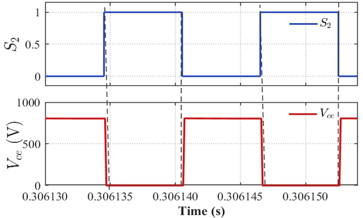
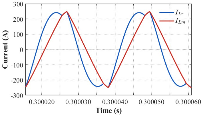
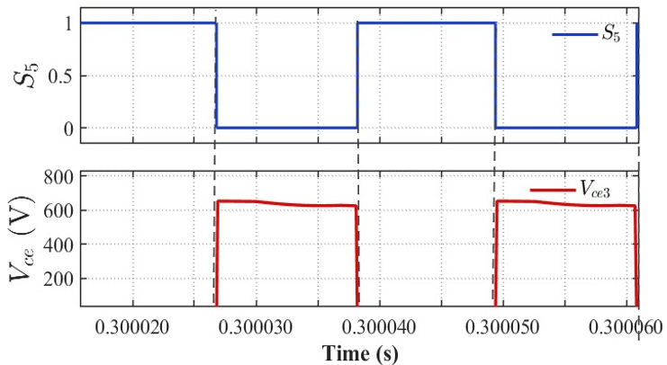
Resonant current and magnetizing currents of the LLC resonant converter on the PV side are presented in Figure 13(a). It can be seen that the waveform of the resonant current is quasi-sinusoidal, while the waveform of the magnetizing current is linear. Figure 13(b) illustrates that the switching process of the converter operates in the soft switching mode in the discharging period at around 0.3 seconds. Although the condition of the PV input voltage is lowered in this discharging period, the voltage between the collector-emitter becomes almost zero before applying the gate signal, which indicates successful ZVS operation. From the above results, it can be concluded that the proposed LLC converter maintains robust ZVS operation throughout the varying switching frequency generated by the MPPT algorithm, validating the resonant tank design and demonstrating the suitability of the converter for efficient PV-side power processing.
(a)
(b)
Figure 13. PV-side LLC-RC performance: (a) resonant and magnetizing currents, and (b) gate signal and switch voltage
5.1.2 CLLLC-RC performance
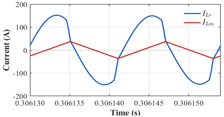
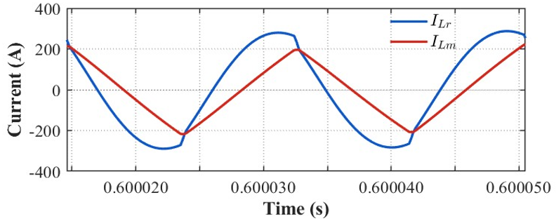
The bidirectional CLLLC converter is evaluated under both charging and discharging conditions to verify its soft-switching capability in reverse power-flow operation. Figure 14(a) shows the gate signal and switch voltage of the CLLLC converter during the charging interval. The switch voltage decreases to nearly zero before the gate signal is applied, confirming ZVS during turn-on. This verifies that the CLLLC converter maintains soft-switching operation during battery charging, thereby reducing turn-on losses and semiconductor voltage stress. Figure 14(b) presents the resonant and magnetizing currents during the charging interval. The resonant current exhibits an oscillatory waveform, while the magnetizing current varies almost linearly, indicating proper resonant-tank operation.
(a)
(b)
Figure 14. Battery-side CLLLC-RC performance during charging: (a) resonant and magnetizing currents, and (b) gate signal and switch voltage
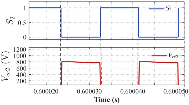
The gate signal and switch voltage in discharging stage are shown in Figure 15(a). Zero switch voltage at the beginning confirms the fact that soft switching property holds good even in discharge mode. The resonant and magnetizing currents in discharging mode are shown in Figure 15(b). The same pattern is seen after reversal of power flow direction, confirming stable bidirectional resonant operation.
(a)
(b)
Figure 15. Battery-side CLLLC-RC performance during discharging: (a) resonant and magnetizing currents, and (b) gate signal and switch voltage
Overall, these results confirm that the CLLLC converter maintains the required resonant behavior and soft-switching operation in both power-flow directions.
5.2 Five-mode power-flow verification under different battery-side CLLLC control strategies
This section presents a comparative evaluation of the proposed battery-side CLLLC control strategies during five-mode power-flow operation.
5.2.1 Conventional single-PI-controlled operation
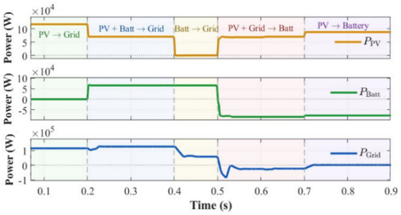
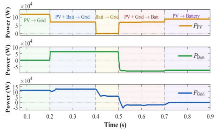
Figure 16 presents the dynamic power flow across the five operating modes under the conventional single PI controller.
Figure 16. Power flow across the five operating modes under the conventional PI controller
Upon entry into Mode 4, initiated at t = 0.50 s, the grid power undergoes a pronounced oscillatory transient, dropping sharply to approximately −100,000 W, rebounding back toward zero, before finally settling at a steady-state value of approximately −20,000 W within 50 ms. The PV array re-converges to its maximum power point within approximately 10 ms, while the battery power remains stable throughout, exhibiting only a gradual monotonic increase consistent with progressive battery charging.
5.2.2 Coordinated dual-PI-controlled operation
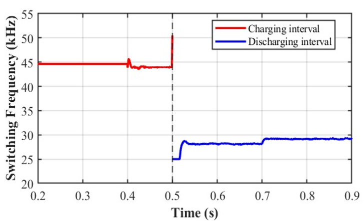
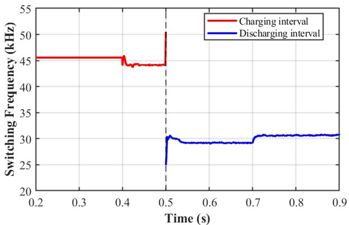
The reason for using the proposed dual-PI control scheme, as opposed to having only one PI controller operating at a time and then switching to another depending on charging or discharging status, should be assessed with respect to the controller output, which is the switching frequency. Figure 17 demonstrates the comparison of the switching frequency command signal when only one PI controller is used with the switching frequency command signal when both PI controllers are working simultaneously using the proposed dual-loop approach. As can be seen, the generated frequency signals are very similar in both cases. However, what is more importantly, the switching frequency stays in the designed operating range providing soft-switching conditions, specifically the ZVS region. Thus, the simultaneous operation of two PI controllers does not cause any abnormal frequency variation and does not take the resonant converter out of the soft-switching region. The proposed dual-PI control scheme, therefore, not only is an extra control layer but also is a justified engineering approach improving the control coordination without violating ZVS conditions.
(a)
(b)
Figure 17. Switching-frequency profiles during charging and discharging intervals: (a) conventional PI controller and (b) proposed coordinated dual-PI controller
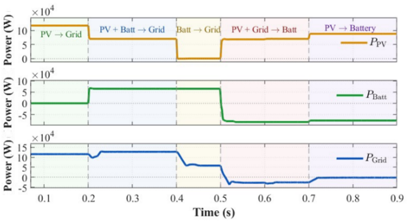
Figure 18 shows the power flow curves of the dual-PI control scheme that is employed in order to coordinate the transitions between the five modes. As soon as Mode 4 starts, at t = 0.50 s, the power of the grid becomes negative and reaches -50,000 W for the first moment, but then stabilizes to a value of -20,000 W in 30 ms. This is a considerable improvement in terms of transient magnitude and settling time compared to the single-PI control. The power of the PV array again converges to the maximum power point in approximately 5 ms, whereas the power of the battery grows monotonically with progressive battery charging.
Figure 18. Power flow across the five operating modes under the coordinated dual-PI controller
5.2.3 Dual-PI-controlled operation with adaptive current limiting
The dynamic power flow through the five different modes of operation in the presence of the dual-loop parallel PI controller along with hardware-assisted current limiting is shown in Figure 19.
Figure 19. Power flow across the five operating modes under coordinated dual-PI controller with adaptive current limiting
Once the system transitions into Mode 4 from t = 0.50 s, the power from the grid decreases down to roughly −25,000 W, finally stabilizing around −20,000 W in 25 ms, thus showing an even smaller transient magnitude and a smaller settling time compared to the dual PI controller. The power of the PV array converges back to its maximum value in about 5 ms, whereas the battery power remains constant throughout with a monotonic increase, consistent with progressive battery charging.
5.2.4 MPC operation
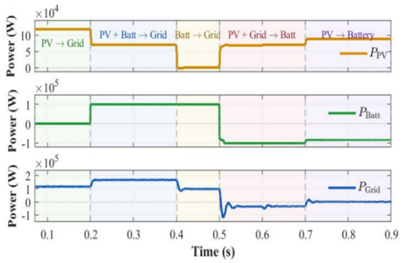
Figure 20 presents the dynamic power flow across the five operating modes under the proposed MPC. Upon entry into Mode 4, initiated at t = 0.50 s, the grid power drops sharply to approximately −100,000 W before settling at −20,000 W within 30 ms. The PV array re-converges to its maximum power point within approximately 10 ms, while the battery power remains stable throughout with a gradual monotonic increase consistent with progressive battery charging.
Figure 20. Power flow across the five operating modes under the model predictive controller
5.3 Grid-side power-quality assessment
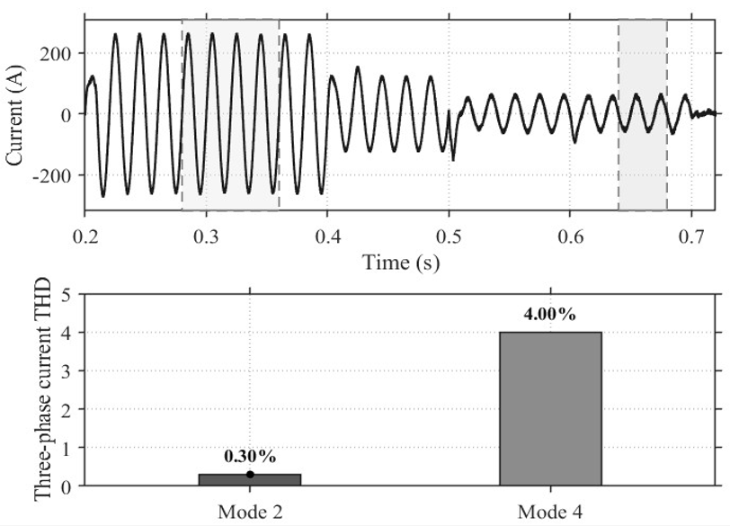
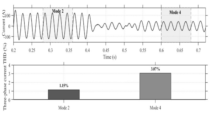
Power quality evaluation on the grid side was done based on choosing two modes that best represent the operating mode, as illustrated in Figures 21 and 22. Mode 2 was chosen since the PV system and the battery charge the grid, meaning there is a situation of generating power from both sources. Mode 4 was chosen since there is charging of the battery from the grid, where the charging of the battery becomes a non-linear load and can affect the grid current quality. Three-phase current THD was calculated for the currents of the grid in both modes to test the harmonic quality against the 5% limit of IEEE Std 519 [20]. From the bottom figures, the predictive control provides less distortion of the current compared to dual loop, especially in Mode 4. This is achieved mainly due to fast adjustment of frequency by the predictive controller, which smooths the current response during the transition and reduces the harmonic components injected into the grid.
Figure 21. Grid-current waveform and corresponding current THD during Modes 2 and 4 using the proposed coordinated dual-PI controller
Figure 22. Grid-current waveform and corresponding current THD during Modes 2 and 4 using the proposed model predictive control (MPC)
5.4 Comparative dynamic performance
All four control strategies investigated in this work are implemented upon the CLLLC-RC operating under variable-frequency control, wherein the switching frequency is continuously adjusted by the respective controller to regulate the output current and voltage. As established in 5.2, operation above the series resonant frequency guarantees an inductive resonant tank impedance at every switching instant [21], ensuring that the resonant inductor current lags the applied voltage and provides sufficient circulating energy to discharge the switch output capacitance to zero prior to gate turn-on. Consequently, ZVS is inherently maintained across all four control strategies under normal steady-state and gradual transient conditions, and no additional snubbing or active gate-drive intervention is required to preserve soft-switching operation.
The one and only exception to this universal ZVS feature is seen in the Dual PI Control Scheme with Hardware Assistance Current Limitation mechanism, but strictly in instances of critical transitions between the operating modes. In such system, whenever the battery current is larger than the adaptive hardware limit obtained proportional to the current reference produced by the software controller, the hardware comparator quickly interrupts the output of the pulse frequency unit using the logic gate mechanism, thus interrupting instantly the gate signal regardless of the current switching frequency. Though this intervention helps greatly in preventing the battery and the entire converter from any further harm in case of an overcurrent problem, it temporarily stops the process of resonant commutation cycle just before the voltage across the switch reaches zero, thus making for a momentary interruption of the ZVS. It should be stressed, however, that this hard switching cycle does not repeat or even continue; it happens once when the overcurrent limit crossing occurs in case of a sudden power transition.
The importance of the distinction is especially clear when looking at Mode 4 switchovers, where the battery converter must undergo a sudden changeover from being in a discharging state to being in a charging state for the purpose of achieving system-wide power balancing. The battery energy storage system assumes an important function here, as it holds down the DC-bus voltage during the process of synchronising the grid, supplies the re-energising current needed by the PV array MPPT reconvergence process, and acts as a sink for the excess power being supplied by the grid in the course of the charging process. In other words, the effectiveness of each control strategy’s management of the battery current transition task defines the level of stress experienced by the converter as part of the process, and forms the main criterion used in comparing the four strategies in Table 8.
Table 8. Comparative dynamic performance of the four control strategies
|
Metric |
Single PI |
Dual PI (Parallel) |
Dual PI + Hardware |
MPC |
|
Peak Transient (W) |
−100,000 |
−50,000 |
−25,000 |
−100,000 |
|
Settling Time (ms) |
50 |
30 |
25 |
30 |
|
PV Re-sync Time (ms) |
10 |
5 |
5 |
10 |
|
Power Quality — THD (%) |
- |
- |
Within limits, Good |
Within limits, Superior |
|
Implementation Complexity |
Low |
Medium |
High |
Medium |
|
Tuning Parameters |
2 |
4 |
5 |
2 |
|
Computational Demand |
Low |
Low |
Low |
Medium |
|
Mode Transition Performance |
Good |
Good |
Excellent |
Good |
|
Stability Across All Modes |
Good |
Good |
Good |
Good |
5.5 Limitations
All results are obtained from time-domain simulation. Sensor noise, common-mode coupling into the current-sensing path, and drift of the resonant-tank parameters with temperature and ageing are not represented, and the execution times in Section 2.5 are derived from the algorithm's operation count rather than measured on target hardware. Hardware-in-the-loop testing, followed by a reduced-scale prototype of the battery-side CLLLC-RC and its adaptive limiter, is the principal item of future work.
Due to the simplicity in its design and fewer components along with wider ZVS operational range, the unidirectional LLC-RC topology was found most suitable for the PV interface for efficient PV power conversion without bidirectionality requirements.
On the other hand, due to the symmetrical nature of the resonant converter circuit, the bidirectional CLLLC-RC topology was found most appropriate on the battery side for efficient power conversion and voltage-gain capabilities in both charging and discharging modes with ZVS conditions.
Dual-PI control was found more efficient than the traditional single-PI control in regulating voltage and current simultaneously during operating-mode transitions without switching between the CC and CV control based on mode changes. Hardware-supported protection becomes necessary for the resonant power converters due to the lack of fast response through software control alone. In that way, integrating intelligent control with fast and cycle-by-cycle current limitation becomes an effective approach for addressing the problem of transient overcurrent and protecting the converter. Predictive frequency control is a good option for the coordinated dual-PI control, since it provides similar performance in dynamic conditions but less current distortion and smooth switching frequency change and just two parameters to tune. The whole hybrid photovoltaic-battery system thus offers efficient multimode operation, stable DC-link voltage, high energy conversion efficiency, unity power factor, and quality grid currents meeting the IEEE requirements, confirming its suitability for grid-connected renewable-energy applications.
[1] Daud, M.Z., Mohamed, A., Hannan, M.A. (2014). An optimal control strategy for DC bus voltage regulation in photovoltaic system with battery energy storage. The Scientific World Journal, 2014: 1-16. https://doi.org/10.1155/2014/271087
[2] Marahatha, A., Dhami, S., Karki, M. (2026). Modeling and control of an islanded DC microgrid with a solar–wind–battery system. Oodbodhan, 9(1): 91-98. https://doi.org/10.3126/oodbodhan.v9i1.95651
[3] Imtiaz, S., Yang, L., Munir, H.M., Memon, Z.A., Kilic, H., Naz, M.N. (2025). DC‐link voltage stability enhancement in intermittent microgrids using coordinated reserve energy management strategy. IET Renewable Power Generation, 19(1): e13197. https://doi.org/10.1049/rpg2.13197
[4] Jean-Pierre, G., El Shafei, A., Altin, N., Nasiri, A. (2019). A multiport bidirectional LLC resonant converter for grid-tied photovoltaic-battery hybrid system. In 2019 8th International Conference on Renewable Energy Research and Applications (ICRERA), Brasov, Romania, pp. 755-760. https://doi.org/10.1109/ICRERA47325.2019.8996775
[5] Infineon Technologies AG (2024). Operation and modeling analysis of a bidirectional CLLC converter: REF-DAB11KIZSICSYS—An example of the 11 kW bidirectional design. Application Note AN-2024-06, Rev. V1.0.
[6] Nkembi, A.A., Santoro, D., Ahmad, F., Kortabarria, I., Cova, P., Sacchi, E., Delmonte, N. (2024). Novel droop-based techniques for dynamic performance improvement in a linear active disturbance rejection controlled-dual active bridge for fast battery charging of electric vehicles. Energies, 17(20): 5171. https://doi.org/10.3390/en17205171
[7] Wen, C., Wei, Y., Wang, P., Li, J., Zhou, J., Li, Q. (2024). Modular system of cascaded converters based on model predictive control. Energy Engineering, 121(11): 3241–3261. https://doi.org/10.32604/ee.2024.051810
[8] Tarisciotti, L., Chen, L., Shao, S., Dragicevic, T., Wheeler, P., Zanchetta, P. (2021). Finite control set model predictive control for dual active bridge converter. IEEE Transactions on Industry Applications, 58(2): 2155–2165. https://doi.org/10.1109/tia.2021.3135373
[9] Chen, L., Lin, L., Shao, S., et al. (2019). Moving discretized control set model-predictive control for dual-active bridge with the triple-phase shift. IEEE Transactions on Power Electronics, 35(8): 8624-8637. https://doi.org/10.1109/tpel.2019.2962838
[10] Yang, B., Lee, F., Concannon, M. (2003). Over current protection methods for LLC resonant converter. In 18th Annual Applied Power Electronics Conference - APEC 2003, Miami Beach, FL, USA, pp. 605-609. https://doi.org/10.1109/APEC.2003.1179276
[11] Zaikin, D.I. (2015). Short‐circuit protection of LLC resonant converter using voltages across resonant tank elements. The Journal of Engineering, 2015(6): 205-207. https://doi.org/10.1049/joe.2015.0079
[12] Yang, B., Chen, Y., Ruan, W., Liu, H., Ren, Y., Mai, R. (2021). Current stress optimization for double-sided CLLLC topology-based IPT system with constant output current tolerating pad misalignments. IEEE Transactions on Industry Applications, 58(1): 1032-1043. https://doi.org/10.1109/tia.2021.3125281
[13] Semiconductor Components Industries, LLC. (2023). Half-Bridge LLC Resonant Converter Design Using NCP4390/NCV4390. Application Note AND9408/D. USA: onsemi. https://www.onsemi.com/.
[14] Yang, B., Lee, F., Zhang, A., Huang, G. (2002). LLC resonant converter for front end DC/DC conversion. In APEC 2002 - Applied Power Electronics Conference and Exposition, Dallas, TX, USA, pp. 1108-1112. https://doi.org/10.1109/APEC.2002.989382
[15] Ding, H., Zhu, J., Yuan, H. (2026). Research on parameter design and control strategy of bidirectional CLLC resonant converter. International Journal of Electric Power and Energy Studies, 5(2): 1-12. https://doi.org/10.62051/ijepes.v5n2.01
[16] Chen, P.F. (2008). Battery charger for preventing charging currents from overshooting during mode transition and method thereof, U.S. Patent 7 405 539 B2. https://patentimages.storage.googleapis.com/fe/47/8d/e6d9b17e55b444/US20060113966A1.pdf.
[17] Vazquez, S., Rodriguez, J., Rivera, M., Franquelo, L.G., Norambuena, M. (2017). Model predictive control for power converters and drives: Advances and trends. IEEE Transactions on Industrial Electronics, 64(2): 935-947. https://doi.org/10.1109/TIE.2016.2625238
[18] Blaabjerg, F., Teodorescu, R., Liserre, M., Timbus, A.V. (2006). Overview of control and grid synchronization for distributed power generation systems. IEEE Transactions on Industrial Electronics, 53(5): 1398-1409. https://doi.org/10.1109/TIE.2006.881997
[19] Reznik, A., Simões, M.G., Al-Durra, A., Muyeen, S.M. (2014). LCL filter design and performance analysis for grid-interconnected systems. IEEE Transactions on Industry Applications, 50(2): 1225-1232. https://doi.org/10.1109/TIA.2013.2274612
[20] IEEE. (2014). IEEE Std 519-2014: IEEE recommended practice and requirements for harmonic control in electric power systems. IEEE, New York, USA. https://doi.org/10.1109/IEEESTD.2014.6826459
[21] Jung, J.H., Kim, H.S., Ryu, M.H., Baek, J.W. (2013). Design methodology of bidirectional CLLC resonant converter for high-frequency isolation of DC distribution systems. IEEE Transactions on Power Electronics, 28(4): 1741-1755. https://doi.org/10.1109/TPEL.2012.2213346