Van Tien Nguyen*![]() | Khac Tiep Do
| Khac Tiep Do![]()
© 2026 The authors. This article is published by IIETA and is licensed under the CC BY 4.0 license (http://creativecommons.org/licenses/by/4.0/).
OPEN ACCESS
This paper proposes an advanced trajectory tracking and energy optimization control framework for 6-degree-of-freedom (6-DOF) Autonomous Underwater Vehicles (AUV) operating under the complex disturbances of ocean currents. To overcome the inherent limitations of traditional disturbance rejection methods, this study introduces an active environment-adaptive strategy integrating a Finite-Time Extended State Observer (FTESO) with Model Predictive Control (MPC). The FTESO exploits a non-smooth error feedback mechanism to achieve fast and accurate convergent estimation of environmental disturbances. Concurrently, the MPC employs a self-tuning multi-objective cost function; by directly mapping the observed disturbance intensity into the weighting matrices, the system dynamically balances reference tracking accuracy against control effort. Comprehensive simulations conducted on the REMUS 100 AUV model under severe hydrodynamic scenarios—including ocean currents at 30° and 120° angles, as well as vortex ocean current fields—validate the superiority of the proposed approach. Quantitative analyses demonstrate that, compared to conventional MPC and MPC with a Linear Extended State Observer (LESO) framework, the proposed FTESO-MPC algorithm not only substantially reduces directional instability and significantly minimizes cross-track errors but also improves propulsion efficiency. Notably, compared to the conventional MPC, the proposed algorithm achieves a substantial reduction of up to 41.67% in total system energy consumption across the simulated scenarios.
Autonomous Underwater Vehicles, Model Predictive Control, Finite-Time Extended State Observer, trajectory tracking energy optimization
The dynamics of Autonomous Underwater Vehicle (AUV) constitute a highly nonlinear system characterized by complex cross-coupling among degrees of freedom and inherent underactuated properties. In practical maritime operations, these baseline characteristics are further complicated by unknown external disturbances, particularly spatiotemporally varying ocean currents. Over the past decade, various robust control architectures—including sliding mode control and backstepping—have been widely deployed to enforce trajectory tracking under such uncertainties [1, 2]. Among modern control frameworks, Model Predictive Control (MPC) stands out as a highly effective trajectory optimization solution due to its unique capability to explicitly handle multi-variable actuator constraints [3, 4]. However, the accuracy and recursive feasibility of conventional robust MPC (or Tube-MPC) degrade severely when the system is subjected to unmeasurable ocean currents. A minor discrepancy in the nominal prediction model can accumulate rapidly along the prediction horizon, leading to steady-state tracking errors or even total destabilization of the closed-loop system [5, 6].
To actively address this disturbance compensation problem, active disturbance rejection control principles have been widely integrated into the MPC frameworks of marine robotics [7, 8]. Traditional methodologies utilizing neural networks or Linear Extended State Observers (LESO) estimate lumped disturbances as an extended state to perform feed-forward compensation [9]. Nevertheless, these asymptotic observers often suffer from significant phase lag and slow convergence when disturbance amplitudes fluctuate abruptly. Recently, the application of Finite-Time Extended State Observer (FTESO) has emerged as a superior alternative for AUV [10, 11]. By leveraging a non-smooth fractional feedback structure, the FTESO guarantees that estimation errors strictly converge to a small neighborhood of the origin within a mathematically bounded time frame, regardless of the initial conditions [12, 13]. This near-instantaneous convergence is remarkably crucial when coupled with MPC, as it strictly satisfies the separation principle and ensures the optimizer receives highly precise spatial disturbance updates.
Although the integration of FTESO and MPC effectively addresses trajectory deviation, a significant blind spot persists in the current literature regarding energy-aware and environment-adaptive control philosophies. Most contemporary control studies [12-14] rigidly employ an additive disturbance cancellation approach. In this paradigm, the controller attempts to generate an anti-phase signal to completely neutralize the hydrodynamic drag of ocean currents to strictly maintain a nominal reference velocity. From the perspectives of energy consumption and finite actuator limits, this is an impractical design strategy. Attempting to sustain high advance speeds when an AUV enters a region with strong counter-currents demands immense control effort, inevitably forcing the thrusters into saturation and rapidly depleting the vehicle's battery reserves. The underlying critical issue is the complete absence of an environment-awareness mechanism at the optimization level, where the AUV could proactively yield to overwhelming environmental resistance to survive and optimize its energy expenditure.
To bridge this research gap, this paper proposes a novel control framework for AUV, integrating the rapid estimation capabilities of the FTESO with the flexible optimization mechanism of MPC. The core distinction of this research lies in transitioning the paradigm from disturbance rejection to active disturbance adaptation. The main contributions of this paper are summarized as follows:
2.1 Mathematical 6-degree-of-freedom model of the Autonomous Underwater Vehicle under environmental disturbances
To design a spatial trajectory tracking and omnidirectional disturbance compensation controller, establishing a comprehensive mathematical model that describes the kinematics and dynamics of the AUV in a 6-degree-of-freedom (6-DOF) space is a prerequisite. The system utilizes two standard reference coordinate frames: the Earth-fixed frame {E} and the Body-fixed frame {B}, as illustrated in Figure 1.

Figure 1. Body-fixed and earth-fixed frame of Autonomous Underwater Vehicle (AUV)
The motion of the AUV in 3D space comprises six components: three translational motions (surge, sway, heave) and three rotational motions (roll, pitch, yaw). Let the position and Euler angle state vector in the $\{E\}$ frame be defined as $\eta=[x, y, z, \phi, \theta, \psi]^T$, and the linear and angular velocity vector in the $\{B\}$ frame as $v=[u, v, w, p, q, r]^T$. The kinematic equation describing the transformation relationship between the two coordinate frames is expressed as follows:
$\dot{\eta}=J(\eta) v$ (1)
where, $J(\eta) \in R^{6 \times 6}$ is the coordinate transformation matrix, composed of two 3 × 3 block matrices:
$J(\eta)=\left[\begin{array}{cc}J_1\left(\eta_2\right) & 0_{3 \times 3} \\ 0_{3 \times 3} & J_2\left(\eta_2\right)\end{array}\right]$ (2)
with $\eta_2=[\phi, \theta, \psi]^T$ and $J_1\left(\eta_2\right)$ is the directional cosine matrix used to transform the translational velocities, and $J_2\left(\eta_2\right)$ is the transformation matrix for angular velocities from the {B} frame to the {E} frame. Based on the Newton-Euler equations of motion for rigid bodies in fluids [15, 16], the general 6-DOF dynamic equation of the AUV under environmental disturbances is written in matrix form:
$M \dot{v}+C(v) v+D(v) v+g(\eta)=\tau+\tau_{\text {enn }}$ (3)
where, $M=M_{R B}+M_A \in R^{6 \times 6}$ is the inertia mass matrix; $C(v)=C_{R B}(v)+C_A(v) \in R^{6 \times 6}$ is the matrix of Coriolis and centripetal forces; $D(v)=D_l+D_{n l}(v) \in R^{6 \times 6}$. is the hydrodynamic damping matrix; $g(\eta) \in R^6$ is the vector of restoring forces and moments; $\tau=\left[\tau_u, \tau_v, \tau_w, \tau_p, \tau_q, \tau_r\right]^T \in R^6$ is the control force and moment vector generated by the actuators (propellers, horizontal hydroplanes, and vertical rudders); $\tau_{e n v} \in R^6$ is the external environmental disturbance vector.
When considering the effect of ocean currents with a spatial velocity of $V_c=\left[V_x, V_y, V_z, 0,0,0\right]^T$ in the $\{E\}$ frame, the relative velocity of the AUV in the $\{B\}$ frame is $v_r=v- J^{-1}(\eta) V_c$ [17]. The alteration of the hydrodynamic field caused by $v_r$ leads to variations in the C and D matrices, generating significant nonlinear deviations from the static nominal model. All these disturbances are lumped into the $\tau_{e n v}$ vector.
Let the extended state variables of the system be defined as $x_1=\eta \in R^6$ (position and attitude angles) and $x_2=\dot{\eta} \in R^6$. (velocity in the Earth-fixed frame). From Eq. (1), we obtain:
$\begin{aligned} \dot{x}_2=\dot{J}(\eta) J^{-1}(\eta) x_2 & -J(\eta) M^{-1}\left(C\left(J^{-1} x_2\right) J^{-1} x_2\right. \left.+D\left(J^{-1} x_2\right) J^{-1} x_2+g\left(x_1\right)\right) +J(\eta) M^{-1} \tau+J(\eta) M^{-1} \tau_{e n v}\end{aligned}$ (4)
To standardize this into the input equation form for the observer and controller, we define the system dynamic components in the $R^6$ space:
$\begin{aligned} f\left(x_1, x_2\right)=\dot{J}(\eta) & J^{-1}(\eta) x_2 -J(\eta) M^{-1}\left(C\left(J^{-1} x_2\right) J^{-1} x_2\right. \left.+D\left(J^{-1} x_2\right) J^{-1} x_2+g\left(x_1\right)\right)\end{aligned}$ (5)
$B\left(x_1\right)=J(\eta) M^{-1}$ (6)
$d(t)=B\left(x_1\right) \tau_{\text {env }}+\Delta f\left(x_1, x_2\right)$ (7)
where, $\Delta f\left(x_1, x_2\right)$ represents the deviation caused by parameter uncertainties in matrices $M, C, D$ and the restoring vector $g ; B\left(x_1\right)$ is the control input gain matrix; $d(t)$ is the lumped disturbance vector. Finally, the 6-DOF mathematical model of the AUV is compactly expressed in the standard state-space form [18, 19]:
$\left\{\begin{array}{l}\dot{x}_1=x_2 \\ \dot{x}_2=f\left(x_1, x_2\right)+B\left(x_1\right) u_c+d(t)\end{array}\right.$ (8)
This mathematical model provides a unified mathematical foundation for the FTESO framework to execute observation and disturbance compensation for each DOF independently and instantaneously.
To ensure a fully reproducible evaluation of the proposed FTESO-MPC framework, the numerical simulations are formulated based on the verified mathematical model of the REMUS 100 AUV [16], which is detailed in Table 1.
Table 1. Hydrodynamic and physical parameters of the REMUS 100 Autonomous Underwater Vehicle (AUV) [16]
|
Parameter |
Symbol |
Value |
Unit |
|
Mass |
m |
30.48 |
kg |
|
Weight |
W |
299 |
N |
|
Buoyancy |
B |
306 |
N |
|
CoG |
$\begin{aligned} & r_G =\left[x_G, y_G, z_G\right]^T\end{aligned}$ |
[0, 0, 0.0196] |
m |
|
Center of buoyancy |
$\begin{aligned} & r_B =\left[x_B, y_B, z_B\right]^T\end{aligned}$ |
[0, 0, 0]T |
m |
|
Roll, Pitch, Yaw inertia |
$I_x, I_y, I_z$ |
0.177, 3.45, 3.45 |
kg·m² |
|
Surge, Sway, Heave added mass |
$X_{\dot{u}}, Y_{\dot{v}}, Z_{\dot{w}}$ |
-0.93, -35.5, -35.5 |
kg |
|
Roll, Pitch, Yaw added mass |
$K_{\dot{p}}, M_{\dot{q}}, N_{\dot{r}}$ |
-0.0704, -4.88, -4.88 |
kg·m² |
|
Max longitudinal thrust |
$\tau_{u, \max }$ |
200 |
N |
|
Max stern plane limit |
$\delta_{s \max }$ |
± 20 |
deg |
|
Max vertical rudder limit |
$\delta_{r \max }$ |
± 20 |
deg |
|
Max rudder slew rate |
$\dot{\delta}_{\max }$ |
± 5 |
deg/s |
2.2 Finite-Time Extended State Observer design
2.2.1 Finite-Time Extended State Observer structure
To actively counteract environmental disturbances, the underlying principle is to augment the system by treating the lumped disturbance $d(t)$ in Eq. (8) as an extended state $x_3= d(t)$, with its derivative denoted as $\dot{x}_3=h(t)$. Traditional linear observers often only achieve asymptotic convergence as time approaches infinity, resulting in significant phase lag when ocean currents fluctuate abruptly. To overcome this, this paper employs an FTESO framework utilizing non-smooth error feedback to achieve rapid convergence [20, 21]:
$\left\{\begin{array}{l}\dot{z}_1=z_2-\beta_1 \operatorname{sig}^{\alpha_1}\left(e_1\right) \\ \dot{z}_2=z_3+f\left(x_1, z_2\right)+B u_c-\beta_2 \operatorname{sig}^{\alpha_2}\left(e_1\right) \\ \dot{z}_3=-\beta_3 \operatorname{sig}^{\alpha_3}\left(e_1\right)\end{array}\right.$ (9)
where, $\left(z_1, z_2, z_3\right)$ are the respective estimated values of the states $\left(x_1, x_2\right)$ and the disturbance $x_3 \cdot e_1=z_1-x_1$ represents the measurable position observation error. The fractional power sign function is defined as $\operatorname{sig}^\alpha\left(e_1\right)=\left|e_1\right|^\alpha \operatorname{sgn}\left(e_1\right)$, which provides a large observation gain when the error approaches zero, thereby accelerating the convergence rate. The observer gains $\beta_1, \beta_2, \beta_3>0$ are selected such that the characteristic polynomial $s^3+\beta_1 s^2+\beta_2 s+\beta_3=0$ satisfies the Hurwitz stability criterion [22]. The exponents $\alpha_1, \alpha_2, \alpha_3 \in(0,1)$ are designed based on geometric homogeneity theory.
2.2.2 Stability analysis of the Finite-Time Extended State Observer
To prove the finite-time convergence of the FTESO, we define the estimation error vector as $e=\left[e_1, e_2, e_3\right]^T$ where $e_i=x_i-\hat{x}_i$. Based on Eqs. (8) and (9), the error dynamics are formulated as:
$\left\{\begin{array}{c}\dot{e}_1=e_2-\beta_1\left[e_1\right]^{\alpha_1} \\ \dot{e}_2=e_3-\beta_2[e]^{\alpha_2} \\ \dot{e}_3=h(t)-\beta_3\left[e_1\right]^{\alpha_3}\end{array}\right.$ (10)
where, $h(t)=\dot{d}(t)$ is the derivative of the lumped disturbance. Assumption 1: The disturbance rate is bounded by a known constant $L(|h(t)| \leq L)$, which is physically reasonable given the finite energy of ocean currents.
According to the geometric homogeneity framework [20], by selecting the gains $\beta_i$ such that $s^3+\beta_1 s^2+\beta_2 s+\beta_3$ is Hurwitz, and fractional powers as $\alpha_1=\alpha \in(1-\epsilon, 1), \alpha_2= 2 \alpha-1$, and $\alpha_3=3 \alpha-2$.
The nominal unperturbed system $(h(t)=0)$ is globally finite-time stable due to its negative homogeneity degree $\kappa= \alpha-1<0$.
For the perturbed system $(h(t) \neq 0)$, taking a homogeneous Lyapunov function $V(e)$ of degree $p$, its time derivative satisfies $\dot{V} \leq-c_1 V^{\frac{p+K}{p}}+c_2 L\|e\|^{p-1}$ for strictly positive constants $c_1, c_2$. This inequality guarantees that the estimation errors are robustly driven into a small neighborhood of the origin within a bounded finite time $T \leq \frac{p}{c_1|\kappa|} V(e(0))^{\frac{|\kappa|}{p}}$. Crucially, increasing the linear observer gains $\beta_i$ directly enlarges the parameter $c_1$, which proportionally reduces the upper bound $T$, thereby ensuring near-instantaneous disturbance estimation for the MPC framework.
2.3 Model Predictive Control design with an environment-aware cost function
Once the spatial lumped disturbance vector $\hat{d}(t) \in R^6$ is accurately isolated and estimated within a finite time by the FTESO, the subsequent step is to synthesize the 3D trajectory tracking control law. Distinct from conventional MPC frameworks that utilize fixed weighting matrices for AUV [6, 9, 21], this study develops an Environment-aware MPC mechanism. The core of this approach is a self-tuning cost function based on the observed disturbance, aiming to thoroughly resolve the conflict between tracking accuracy and actuator saturation risk when the AUV operates in complex ocean current regions.
To implement the MPC controller, the continuous 6-DOF state equation of the closed-loop system (incorporating the feed-forward compensation signal from the FTESO) must be transformed into the discrete-time domain. Utilizing the 4th-order Runge-Kutta (RK4) approximation method with a sampling period $T_s$, the nonlinear prediction model is represented in difference equation form:
$x(k+1)=F_d\left(x(k), u_c(k)\right)+B_d(x(k)) \hat{d}(k)$ (11)
where, $x(k)=\left[\eta^T(k), v^T(k)\right]^T \in R^{12}$ is the augmented state vector at step. $u_c(k)=\tau(k) \in R^6$ is the control force/moment vector. $F_d$ and $B_d$ are the discretized nonlinear functions corresponding to the nominal dynamics. $\hat{d}(k) \in R^6$ is the spatial environmental disturbance provided by the FTESO, which is assumed to be constant throughout a basic prediction period according to the Zero-Order Hold principle.
In the spatial trajectory tracking problem, if fixed penalty weights are employed, maintaining the translational velocity (surge/heave) when encountering high-intensity counter-currents will generate control signals that exceed the physical limits of the propellers. This not only violates the recursive feasibility of the optimizer but also causes severe energy waste [22-24]. To address this, this paper proposes a non-standard cost functional $J(k)$, where the weighting matrices are defined as analytical functions directly dependent on the disturbance vector $\hat{d}(k)$:
$\begin{gathered}J(k)=\sum_{i=1}^{N_p}\left(\left\|\eta(k+i \mid k)-\eta_{\text {ref }}\right\|_{Q_\eta}^2+\| v(k+i \mid k)\right. \\ \left.-v_{\text {ref }} \|_{Q_v(\hat{d})}^2\right)+\sum_{i=0}^{N_c-1}\left\|\Delta u_c(k+i \mid k)\right\|_{R(\hat{d})}^2\end{gathered}$ (12)
where, $N_p$ and $N_c$ are the prediction horizon and control horizon, respectively; $\eta_{\text {ref }}$ and $v_{\text {ref }}$ are the reference state vectors of the 3D trajectory; $Q_\eta \in R^{6 \times 6}$ is a positive semidefinite weighting matrix penalizing deviations in position and attitude angles. This component is kept fixed to ensure directional stability and that spatial deviations do not exceed safety limits; $Q_v(\hat{d}), R(\hat{d}) \in R^{6 \times 6}$ are adaptive weighting matrices that coordinate the balance between velocity error and control effort. The dynamic weight update mechanism for the main diagonal elements of $Q_v$ and $R$ is designed following an exponential function, ensuring continuous differentiability for the optimization problem. For the $j$-th degree of freedom $(j \in\{1 . .6\})$.
$Q_{v, j i}(\hat{d})=q_{\min , j}+\left(q_{0, j}-q_{\min , j}\right) \exp \left(-\lambda_j\left|\hat{d}_j\right|\right)$ (13)
$R_{j j}(\hat{d})=r_{0, j}+\rho_j\left(1-\exp \left(-\gamma_j\left|\hat{d}_j\right|\right)\right)$ (14)
When the AUV enters a strong disturbance zone, causing a sudden increase in $\left|\hat{d}_1\right|$, the velocity penalty weight $Q_{v, 11}$ will asymptotically decay to $q_{\text {min}, 1}$, while the energy penalty cost $R_{11}$ increases. This structural reconfiguration directs the optimizer to lower the priority of strictly tracking the nominal speed (deceleration). Conversely, for the roll and pitch rotational axes, by fine-tuning the sensitivity coefficients $\lambda_j$ and $\gamma_j$ to values near zero for these specific axes, the posture stability is robustly maintained, completely eliminating the risk of capsizing or loss of depth control under the impact of complex vortex ocean currents.
The parameters of the adaptive cost function, including the exponential decay coefficients $\left(\lambda_j, \gamma_j\right)$ and the sensitivity amplitude factor $\left(\rho_j\right)$, are determined heuristically based on the REMUS 100's actuator limits and extensive simulation trials. The decay coefficients $\lambda_j$ and $\gamma_j$ dictate the rate at which the adaptive weights transition when exposed to a specific disturbance intensity $\left|\hat{d}_j\right|$. A sensitivity analysis reveals a clear operational trade-off: setting larger values for $\lambda_j$ and $\gamma_j$ enables the AUV to rapidly deprioritize velocity tracking and severely penalize large rudder inputs during strong counter-currents. This maximizes energy conservation and prevents thruster saturation, albeit causing larger transient spatial deviations. Conversely, selecting excessively small decay coefficients forces the system to strictly maintain the reference path, which minimizes cross-track errors but exponentially drains battery power and risks directional instability. The final adaptive parameters listed in Table 2 represent an optimal empirical balance, ensuring both trajectory robustness and energy efficiency under severe hydrodynamic scenarios.
At each sampling period, the MPC solves a Nonlinear Programming problem to find the optimal control signal sequence $\Delta U_c^*=\left[\Delta u_c(k \mid k), \ldots, \Delta u_c\left(k+N_c-1 \mid k\right)\right]$, subject to the physical constraint inequalities of the actuators:
$u_{\min } \leq u_c(k+i-1 \mid k)+\Delta u_c(k+i \mid k) \leq u_{\max }$ (15)
$\Delta u_{\min } \leq \Delta u_c(k+i \mid k) \leq \Delta u_{\max }$ (16)
Due to the inherent nonlinear nature of the 6-DOF dynamics and the state-disturbance dependent cost function structure, the above optimization problem is solved using the Sequential Quadratic Programming (SQP) algorithm. By integrating the disturbance information $\hat{d}$ from the FTESO, the recursive feasibility of the SQP is significantly improved because the amplitude of the feed-forward compensation signal is actively regulated by the adaptive cost function, completely eliminating the risk of boundary violations for $u_{\max }$ and $u_{\min }$.
2.4 Energy consumption metric formulation
The energy consumption evaluated in this study is formulated as a combined index that comprehensively encompasses both the mechanical propulsion energy required to overcome hydrodynamic drag and the electrical effort consumed by the steering actuators.
The instantaneous propulsion power $P_{\text {prop}}(t)$ required by the main thruster is modeled based on the cubic physical relationship with the relative surge velocity:
$P_{\text {prop }}(t)=\frac{X_{u|u|}}{\eta_{\text {prop }}}\left|u(t)-u_c(t)\right|^3$ (17)
where, $X_{u|u|}$ is the surge quadratic drag coefficient, $\eta_{\text {prop}}$ is the overall propulsion efficiency, $u(t)$ is the actual surge velocity, and $u_c(t)$ is the longitudinal component of the ocean current.
The steering effort $E_{\text {steer}}$, which reflects the energy consumed by the servo motors to continuously actuate the control surfaces, is quantified by integrating the squared fin deflections:
$E_{\text {steer}}=\int_0^T\left(\delta_r^2(t)+\delta_s^2(t)\right) d t$ (18)
The total system energy $E_{\text {total}}$ over the mission duration T is defined as the combined sum of these two components:
$E_{\text {total}}=\int_0^T P_{\text {prop}}(t) d t+k_s \int_0^T\left(\delta_r^2(t)+\delta_s^2(t)\right) d t$ (19)
where, $k_s$ is a conversion weighting factor relating the mechanical steering deflection to equivalent energy. This combined index accurately reflects AUV propulsion energy because it simultaneously penalizes the power wasted by excessive rudder chattering and the exponential battery drain caused by maintaining high relative velocities against severe ocean currents.
2.5 Control structure
The overall control architecture is designed as a hierarchical closed-loop structure, illustrating the interaction between the FTESO and the MPC controller, as depicted in Figure 2. The measured position and attitude vector η_meas from the AUV's sensors is fed back to the FTESO to simultaneously estimate the spatial velocity vector $\hat{v}$ and the lumped disturbance vector $\hat{d} \in R^6$. The fused state information $\hat{x}=\left[\eta_{\text {meas}}^T, \hat{v}^T\right]^T$ is then provided to the MPC as the current state. The novelty of this structure lies in the routing flow of the signal $\hat{d}$. It is not only embedded into the internal prediction model for feed-forward disturbance compensation, but also directly fed into the cost function tuning module to update the weighting matrices $Q_v(\hat{d})$ and $R(\hat{d})$ online.

Figure 2. Overall block diagram of the proposed Finite-Time Extended State Observer and Model Predictive Control (FTESO-MPC)
Based on this continuously reconfigured optimization problem, the SQP solver computes the optimal control force and moment vector τ. Finally, the signal τ is applied to the vehicle's actuators and simultaneously fed back to the FTESO to accurately isolate the active control effort from environmental disturbances, thereby completely closing the operation cycle of the system.
3.1 Simulation setup
To verify the theoretical validity and comprehensively evaluate the performance of the integrated FTESO-MPC control framework, a simulation environment was developed and implemented on the MATLAB platform. The continuous 6-DOF dynamics of the AUV were integrated using the fourth-order Runge-Kutta method with a fixed sampling period, while the constrained multi-objective MPC problem was resolved utilizing the SQP algorithm provided by the MATLAB Optimization Toolbox. The selected research subject is the REMUS 100 autonomous underwater vehicle [16]. All configuration parameters for the FTESO and the MPC are comprehensively specified in Table 2 below.
Table 2. Parameters of the proposed Finite-Time Extended State Observer and Model Predictive Control (FTESO-MPC)
|
Parameter |
Symbol |
Value |
|
Prediction horizon |
Np |
60 |
|
Control horizon |
Nc |
5 |
|
Nominal / Min velocity weights |
$q_{0, j}, q_{\min , j}$ |
50, 10 |
|
Nominal control weights |
$r_{0, j}$ |
600 |
|
Control sensitivity factor |
$\rho_j$ |
400 |
|
Exponential decay coefficients |
$\lambda_j, \gamma_j$ |
0.8, 0.8 |
|
Observer bandwidth |
ω0 |
1.5 |
|
Linear gain coefficients |
$\beta_l, \beta_l, \beta_3$ |
4.5, 6.75, 3.375 |
|
Fractional power coefficients |
$\alpha_1, \alpha_1, \alpha_3$ |
0.5, 0.25, 0.125 |
|
Max cross-track error boundary |
$e_{y, \max}$ |
± 25 m |
|
Max roll angle limit |
$\phi_{\max}$ |
± 15o |
|
Max pitch angle limit |
$\theta_{\max}$ |
± 20o |
|
Max yaw deviation limit |
$\Delta \psi_{\max}$ |
± 45o |
The SQP optimizer was configured with a 0.05 s sampling period, a maximum of 50 iterations, and a constraint tolerance of 10-4 over a 2500 s mission (50,000 steps). The AUV started from rest with an initial pose $\eta_0=[0,0,0,0,0,1.107]^T$. The reference trajectory comprises 9 spatial waypoints with (East, North) coordinates: (0,0), (900, 450), (1100, 650), (1200, 1000), (1450, 1150), (1500, 1550), (1850,1950), (1850, 2400), and (1850, 2600) m. Crucially for real-time applicability, the average and maximum computation times per control cycle were 12.4 ms and 28.7 ms, respectively. Because this worst-case computation time remains strictly bounded below the 50 ms sampling period, the proposed FTESO-MPC inherently satisfies real-time execution constraints.
3.2 Simulation scenarios
To assess the robustness of the FTESO-MPC framework against unknown environmental disturbances, this study devises three ocean current scenarios exhibiting completely distinct impact characteristics: cross-currents at and angles, and a vortex ocean current field. The simulation outcomes of the proposed FTESO-MPC system are directly benchmarked against two baseline controllers: an MPC equipped with a LESO (LESO-MPC) and a conventional MPC without an observation module. The quantitative evaluation metrics encompass the cross-track error and the total energy consumption.
3.2.1 Scenario 1: Evaluation of trajectory tracking and energy optimization under a constant ocean current
To rigorously evaluate robustness, Scenario 1 subjects the AUV to a constant ocean current defined by a magnitude Vc = 2.0 m/s and incidence angles $\beta_c \in\left\{30^{\circ}, 120^{\circ}\right\}$. Notably, 2.0 m/s represents a severe hydrodynamic limit for the REMUS 100 (which has a nominal speed of ≈ 2.5 m/s). This extreme magnitude was intentionally selected to stress-test the adaptive cost function's capability to prevent actuator saturation by proactively yielding to overwhelming environmental forces.
As shown in Figure 3, simulation results reveal that the standard MPC, lacking an active disturbance compensation mechanism, yields pronounced static cross-track errors when subjected to persistent currents. Although integrating a linear observer successfully mitigates trajectory distortion, the system continues to suffer from considerable eastward drift. In contrast, the proposed FTESO-MPC achieves adherence to the reference path. By leveraging a fractional nonlinear error function, the FTESO guarantees finite-time convergence, yielding near-instantaneous disturbance estimations that facilitate highly robust heading stabilization.

(a) AUV’s trajectory under $\beta_{V c}$ = 30o

(b) AUV’s trajectory under $\beta_{V c}$ = 120o
Figure 3. Autonomous Underwater Vehicles (AUV) operational environment and trajectory map in Scenario 1
Figure 4 illustrates the cross-track error and estimated lumped disturbances under ocean currents with incidence angles of 30° and 120°. An analysis of the cross-track errors reveals that cross-currents significantly degrade the standard MPC, resulting in steady-state errors and a critical overshoot of 85 m during severe transient fluctuations (t = 1550 s).
Conversely, augmenting the control architecture with disturbance observers (LESO and FTESO) substantially bolsters system robustness, maintaining near-zero errors along straight trajectory segments. This enhanced tracking performance is quantitatively corroborated by the Root Mean Square Error (RMSE) and Integral Absolute Error (IAE) indices presented in Tables 3 and 4. Furthermore, Figures 4(b)-(d) compare the estimated lumped disturbances. During waypoint maneuvers, the FTESO exhibits a markedly swifter response, whereas the LESO suffers from pronounced phase lag and attenuated estimation amplitude. A magnified temporal window (1200–1500 s) further verifies the FTESO’s rapid convergence to the actual disturbance.

(a) Cross-track error at 30°

(b) Estimated disturbances at 30°

(c) Cross-track error at 120°

(d) Estimated disturbances at 120°
Figure 4. System performance under different ocean current conditions
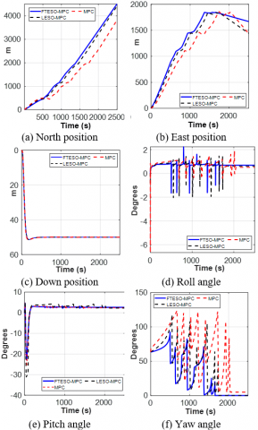
Figure 5. The 6-degree-of-freedom (6-DOF) kinematic states under a 30° ocean current
Figure 5 provides a detailed illustration of the time-domain responses for all six kinematic state variables under a 30° ocean current. Figures 5(a) and (b) demonstrate that the standard MPC lacks adequate drift compensation, resulting in positioning errors. Conversely, both FTESO-MPC and LESO-MPC robustly maintain the AUV's horizontal trajectory. Figure 5(c) confirms dynamic channel decoupling; an independent controller successfully stabilizes the depth at 50 m despite complex horizontal disturbances. Figures 5(d)-(f) evaluate attitude stability, revealing critical hydrodynamic vulnerabilities in the standard MPC. It exhibits severe roll overshoots (± 10°) and substantial pitch fluctuations (nearly 20°) propagating from cross-channel instability. In contrast, the FTESO-MPC rapidly mitigates these oscillatory impulses, constraining both roll and pitch within a highly stable ± 5° envelope. Furthermore, Figure 5(f) highlights yaw dynamics during severe ocean current disturbances (800–1500 s). Unlike the other controllers, only the FTESO-MPC sustains an equilibrium yaw angle through smooth modulations, thereby preventing step-like transient jumps and significantly optimizing actuator power efficiency. The graph in Figure 6 reflects the total system energy, which encompasses both the effort to maintain velocity and the thrust required to overcome hydrodynamic profile drag.

(a) 30° ocean current

(b) 120° ocean current
Figure 6. Total energy consumption of Autonomous Underwater Vehicles (AUV)
Table 3. Tracking performance and energy consumption of Autonomous Underwater Vehicles (AUV) under a 30° ocean current
|
Controller |
RMSE (m) |
IAE (m ⋅ s) |
Total Energy (J) |
Improvement vs. MPC (%) |
|
FTESO-MPC |
19.07 |
23,294.61 |
4.4 × 10⁴ |
16.98% |
|
LESO-MPC |
22.03 |
26,556.20 |
4.9 × 10⁴ |
7.55% |
|
MPC |
66.95 |
228,815.41 |
5.3 × 10⁴ |
- |
Table 4. Tracking performance and energy consumption of Autonomous Underwater Vehicles (AUV) under a 120° ocean current
|
Control |
RMSE (m) |
IAE (m ⋅ s) |
Total Energy (J) |
Improvement vs. MPC (%) |
|
FTESO-MPC |
41.22 |
60,662.67 |
5.7 × 10⁴ |
20.83% |
|
LESO-MPC |
57.50 |
98,275.54 |
6.2 × 10⁴ |
13.89% |
|
MPC |
75.98 |
26,7536.32 |
7.2 × 10⁴ |
- |
The standard MPC exhibits the highest energy consumption, whereas the LESO-MPC demonstrates an intermediate expenditure level. This elevated energy demand in the standard approach stems from severe lateral displacements, which significantly extend the total traveled distance. In contrast, the FTESO-MPC maintains the lowest energy profile by ensuring the AUV follows the shortest path while preserving an optimal hydrodynamic posture. Ultimately, the proposed architecture conserves approximately 17% of the total mission energy relative to the framework lacking a disturbance observer. Tables 3 and 4 summarize the obtained results in Scenario 1 regarding trajectory deviation and energy consumption. The results indicate that the FTESO-MPC not only reduces trajectory tracking errors (RMSE, IAE), but it also enables the AUV to conserve energy.
3.2.2 Scenario 2: Evaluation of trajectory tracking and energy optimization under a vortex ocean current
To evaluate the controller's limits under spatially varying environments, Scenario 2 introduces a nonlinear vortex field centered at $\left(N_c, E_c\right)=(1500,1200) \mathrm{~m}$ with a peak radius $R_v=500 \mathrm{~m}$. For an AUV at position ($N, E$) with a radial distance $r=\sqrt{\left(N-N_c\right)^2+\left(E-E_c\right)^2}$, the current magnitude $V_c$ and direction $\beta_c$ are formulated as:
$\begin{aligned} V_c=V_{\max } \frac{r}{R_v} e^{1-r} / R_v & , \beta_c=a \tan 2\left(E-E_c, N-N_c\right)+\frac{\pi}{2}\end{aligned}$ (20)

(a) AUV’s 2-D trajectory

(b) AUV’s 3-D trajectory
Figure 7. Tracking performance under a spatially-varying nonlinear vortex current
Figure 7(a) depicts the AUV's trajectory in the 2-D horizontal plane, while Figure 7(b) illustrates the trajectory in 3-D space. Unlike earlier scenarios, the vortex field introduces spatially nonlinear disturbances. The most significant control disparity occurs near the vortex center, where the current vector abruptly reverses, peaking at 2 m/s. Lacking predictive capabilities for this sudden sway force reversal, the standard MPC experiences force resonance and severe trajectory overshoot. This transient event similarly exposes the linear filter's limitations, causing the LESO-MPC to exhibit substantial deviation. Conversely, the FTESO-MPC, leveraging a nonlinear observer, effectively compensates for these complex dynamics, demonstrating superior robustness and tracking to the reference path.
Figure 8 presents the time-domain responses of the 6 kinematic state vectors of the AUV. As in Scenario 1, the vortex’s counter-current impedes advance velocity. Standard MPC and LESO-MPC expend excessive energy countering lateral drift, degrading longitudinal speed. Conversely, FTESO-MPC nullifies lateral deviation, effectively preserving kinetic energy.
Figure 8. The 6-degree-of-freedom (6-DOF) kinematic states of the Autonomous Underwater Vehicles (AUV) in Scenario 2
A fundamental distinction emerges in the yaw response. The continuously rotating current induces dense sawtooth yaw oscillations (Figure 8(f)). While the standard MPC overloads, spiking to ~120° to establish a crabbing angle, FTESO-MPC maintains a narrow oscillation bandwidth. Its rapid flow-reversal updates enable proactive rudder actuation, preventing passive drift. Despite lateral deviations, the vortex causes significantly smaller roll (± 2°) and pitch (+ 5°) oscillations compared to the constant current scenarios.
Figure 9(a) presents the cumulative steering effort, and Figure 9(b) illustrates the total system energy. The distinction in Scenario 2 lies in the latter section of the graph (from t = 1700 s onwards). As the AUV begins to exit the vortex core, the disturbance vector gradually diminishes. At this juncture, the solid blue line of the FTESO-MPC transitions to a horizontal plateau at an extremely low level (1.8 rad²·s). Meanwhile, both the LESO-MPC and the standard MPC persistently actuate the rudders, needlessly dissipating 3.5 rad²·s and over 6.0 rad²·s of energy, respectively.
As shown in Table 5, FTESO’s disturbance estimation converges 70% faster than LESO’s. This rapid response reduces trajectory tracking error (IAE) by 40% versus LESO-MPC and fivefold against standard MPC. By optimizing steering effort, FTESO-MPC ultimately conserves up to 41.67% of total system energy compared to traditional MPC.
Notably, despite the severe transient steering challenges in Scenario 2, its total energy consumption (2.8 × 10⁴ J) is lower than in Scenario 1 (4.4 × 10⁴ J). This is physically attributed to the disturbance spatial distribution. While Scenario 1 imposes a persistent 2.0 m/s current across the entire trajectory, the vortex's peak velocity is strictly localized near its core. Thus, the significantly shorter exposure to maximum hydrodynamic drag in Scenario 2 results in a lower cumulative energy integral.

(a) Cumulative steering effort

(b) Total system energy
Figure 9. Energy consumption under the vortex current
Table 5. Results of scenario 2—comparison of tracking performance and energy consumption under a vortex ocean current
|
Control |
RMSE (m) |
IAE (m ⋅ s) |
Esteer (rad2⋅s) |
Total System Energy (J) |
Improvement vs. MPC (%) |
|
FTESO-MPC |
29.95 |
41,047.84 |
1.8 |
2.8 × 10⁴ |
41.67 |
|
LESO-MPC |
33.78 |
65,913.85 |
3.5 |
3.5 × 10⁴ |
36.36 |
|
MPC |
110.4 |
193,479.39 |
6.0 |
5.5 × 10⁴ |
- |
This paper presents a novel FTESO-MPC framework for 6-DOF underactuated AUV. Based on the evaluated numerical simulations, the proposed method demonstrates a good trade-off between trajectory tracking accuracy and energy conservation under complex ocean currents. By providing finite-time disturbance estimation, the FTESO substantially reduces the phase lag commonly observed in traditional linear observers. Integrating these estimations into a dynamically adaptive cost function empowers the controller to proactively yield to severe head-on resistance, thereby preventing actuator saturation. Consequently, under the tested simulation scenarios, the proposed method significantly reduces trajectory tracking errors and conserves up to 41.67% of the total system energy compared to the standard MPC.
While these simulation results are promising, the current method requires further development before practical engineering deployment. The present framework assumes idealized conditions and must be expanded to handle real-world complexities. Therefore, clear next steps for future research include addressing sensor noise, parameter uncertainty, and complex actuator dynamics. Furthermore, achieving and validating the real-time implementation of this algorithm through Hardware-in-the-Loop testing remains a critical prerequisite prior to conducting full-scale sea trials.
This research was supported by the Vietnam Maritime University.
|
Latin Symbols |
|
|
η |
Position and Euler angle vector in the Earth-fixed frame |
|
v |
Linear and angular velocity vector in the Body-fixed frame |
|
u, v, w |
Translational velocities (surge, sway, heave) |
|
p, q, r |
Angular velocities (roll, pitch, yaw) |
|
J(η) |
Coordinate transformation matrix |
|
M |
Mass and inertia matrix (including added mass) |
|
C(ν) |
Coriolis and centripetal matrix |
|
D(ν) |
Hydrodynamic damping matrix |
|
g(η) |
Restoring forces and moments vector (gravity and buoyancy) |
|
Τ |
Control force and moment vector generated by actuators |
|
τd |
Lumped environmental disturbance vector (ocean currents, waves) |
|
Vc |
Ocean current velocity |
|
Np, Nc |
Prediction horizon and control horizon |
|
Q, R |
Weighting matrices for tracking error and control effort |
|
Greek symbols |
|
|
ϕ, θ, ψ |
Attitude angles (roll, pitch, yaw) |
|
ω0 |
Observer bandwidth |
|
αi, βi |
Sensitivity coefficients for adaptive weight update |
|
Ζ |
Position observation error vector |
|
Subscripts |
|
|
$(\hat\cdot)$ |
Estimated value |
|
$(\cdot)_{r e f}$ |
Reference value |
[1] Li, J., Du, J., Sun, Y., Lewis, F.L. (2019). Robust adaptive trajectory tracking control of underactuated autonomous underwater vehicles with prescribed performance. International Journal of Robust and Nonlinear Control, 29(13): 4629-4643. https://doi.org/10.1002/rnc.4659
[2] Dai, L., Zhang, D., Wang, S., Nie, G., Zhu, X., Wang, X. (2025). Trajectory tracking control of an autonomous underwater vehicle under disturbance and model uncertainty. Journal of Marine Science and Engineering, 13(11): 2210. https://doi.org/10.3390/jmse13112210
[3] Teng, Y., Bian, D., Wu, L., Liu, C., Kuang, X. (2026). On swarm-constrained formation tracking control method for master–slave AUVs with dynamic transformations. Journal of Marine Science and Engineering, 14(1): 76. https://doi.org/10.3390/jmse14010076
[4] Liu, C., Li, T., Wu, W., Zheng, H., Li, J., Chu, X. (2024). Event-triggered predictive path following control of autonomous ships with an MMG model. Ocean Engineering, 314: 119582. https://doi.org/10.1016/j.oceaneng.2024.119582
[5] Shi, K., Wang, X., Xu, H. (2021). On the offset-free nonlinear model predictive control for AUV docking. In 2021 WRC Symposium on Advanced Robotics and Automation (WRC SARA), Beijing, China, pp. 117-122. https://doi.org/10.1109/WRCSARA53879.2021.9612699
[6] Yan, Z., Yan, J., Cai, S., Yu, Y., Wu, Y. (2023). Robust MPC-based trajectory tracking of autonomous underwater vehicles with model uncertainty. Ocean Engineering, 286: 115617. https://doi.org/10.1016/j.oceaneng.2023.115617
[7] Wu, Y., Xu, H., Jiang, Z. (2022). A modified active disturbance rejection controller based on radial basis function neural network for AUV attitude control. In 2022 International Conference on Advanced Robotics and Mechatronics (ICARM), Guilin, China, pp. 962-966. https://doi.org/10.1109/ICARM54641.2022.9959462
[8] Hong, H., Yang, Z., Li, J., Xu, G., Xia, Y., Xu, K. (2024). State-transform MPC-SMC-based trajectory tracking control of cross-rudder AUV carrying out underwater searching tasks. Journal of Marine Science and Engineering, 12(6): 883. https://doi.org/10.3390/jmse12060883
[9] Ebrahimpour, M., Lungu, M. (2025). Finite-time path-following control of underactuated AUVs with actuator limits using disturbance observer-based backstepping control. Drones, 9(1): 70. https://doi.org/10.3390/drones9010070
[10] Ali, N., Tawiah, I., Zhang, W. (2020). Finite-time extended state observer based nonsingular fast terminal sliding mode control of autonomous underwater vehicles. Ocean Engineering, 218: 108179. https://doi.org/10.1016/j.oceaneng.2020.108179
[11] Zhang, K., Zhang, W., Wu, Q., Du, X. (2025). Adaptive fixed-time disturbance observer-based anti-saturation distributed sliding mode formation tracking control for multi-underactuated AUVs under lumped disturbances. Ocean Engineering, 339: 122026. https://doi.org/10.1016/j.oceaneng.2025.122026
[12] Liu, Y., An, S., Wang, L., Fan, Z. (2025). Predefined time backstepping control with an adaptive predefined time disturbance observer for underactuated AUV under unknown external disturbance. Ocean Engineering, 340: 122382. https://doi.org/10.1016/j.oceaneng.2025.122382
[13] Guo, L., Liu, W., Li, L., Xu, J., Zhang, K., Zhang, Y. (2024). Fast finite-time super-twisting sliding mode control with an extended state higher-order sliding mode observer for UUV trajectory tracking. Drones, 8(2): 41. https://doi.org/10.3390/drones8020041
[14] Miao, J., Deng, K., Zhang, W., Gong, X., Lyu, J., Ren, L. (2022). Robust path-following control of underactuated AUVs with multiple uncertainties in the vertical plane. Journal of Marine Science and Engineering, 10(2): 238. https://doi.org/10.3390/jmse10020238
[15] Fossen, T.I. (2011). Handbook of Marine Craft Hydrodynamics and Motion Control. John Wiley & Sons, Chichester. https://doi.org/10.1002/9781119994138
[16] Prestero, T. (2001). Verification of a six-degree of freedom simulation model for the REMUS autonomous underwater vehicle. Master's Thesis, Massachusetts Institute of Technology, Cambridge. https://doi.org/10.1575/1912/3040
[17] Zhao, Y., Hu, Z., Du, W., Geng, L., Yang, Y. (2024). Research on modeling method of autonomous underwater vehicle based on a physics-informed neural network. Journal of Marine Science and Engineering, 12(5): 801. https://doi.org/10.3390/jmse12050801
[18] Li, H., Sun, J., Liu, Q. (2024). Three-dimensional path following control for underactuated AUV based on ocean current observer. Journal of Marine Science and Engineering, 8(11): 672. https://doi.org/10.3390/drones8110672
[19] Chen, Y., Hao, S., Gao, J., Wang, J., Li, L. (2025). Fault-tolerant model predictive control for autonomous underwater vehicles considering unknown disturbances. Journal of Marine Science and Engineering, 13(1): 171. https://doi.org/10.3390/jmse13010171
[20] Bhat, S.P., Bernstein, D.S. (2000). Finite-time stability of continuous autonomous systems. SIAM Journal on Control and Optimization, 38(3): 751-766. https://doi.org/10.1137/S0363012997321358
[21] Li, M., Li, C., Zhang, X. (2022). Finite-time extended state observer-based super-twisting sliding mode controller for PMSM drives with inertia identification. IEEE Transactions on Transportation Electrification, 8(2): 1918-1929. https://doi.org/10.1109/TTE.2021.3123646
[22] Ogata, K. (2010). Modern Control Engineering, 5th ed. Prentice Hall, Boston, pp. 212-225.
[23] Fontaine, A.-F., Zhu, D., Chen, N., Pan, Y.-J. (2023). Nonlinear model predictive control for autonomous underwater vehicle trajectory tracking. In 2023 IEEE 2nd Industrial Electronics Society Annual On-Line Conference (ONCON), SC, USA, pp. 1-6. https://doi.org/10.1109/ONCON60463.2023.10431297
[24] Zhu, Y., Sun, B., Liu, X. (2024). Event-triggered model predictive control for trajectory tracking of AUV with an adaptive disturbance observer. In 2024 10th International Conference on Systems and Informatics (ICSAI), Shanghai, China, pp. 1-6. https://doi.org/10.1109/ICSAI65059.2024.10893761