Mohammad Yahya Almuhanna![]() | Wisam S. Hacham*
| Wisam S. Hacham*![]() | Ali A. Al-Rubayee
| Ali A. Al-Rubayee![]() | Maher Yahya Salloom
| Maher Yahya Salloom![]()
© 2025 The authors. This article is published by IIETA and is licensed under the CC BY 4.0 license (http://creativecommons.org/licenses/by/4.0/).
OPEN ACCESS
This study designs, analyzes, and experimentally validates a compact 4/3 low-power magnetorheological (MR) directional control valve, which is kept normally closed—utilizing a strong permanent magnet—and opens proportionally by applying a small electric current to an electromagnetic coil. The Finite Element Method for Magnetics (FEMM) was used to compute magnetic-flux density distributions for permanent-magnet-only and permanent-magnet combined with coil excitation. Bingham‑type constitutive behavior of MR fluids was used to separate viscous and yield‑stress contributions to the pressure drop. FEMM maps show that a properly‑positioned NdFeB permanent-magnet produces magnetic flux densities on the order of a few tenths of a Tesla in the active fluid gaps, sufficient to close the valve in the absence of coil current. Applying a small counter-acting coil current tends the perpendicular flux density in the active gap to zero; the dramatic reduction in yield stress corresponds to a significant drop in valve pressure at low flows.
magnetorheological valve, FEMM, directional control valve, low-power proportional control, permanent magnet
Magnetorheological (MR) fluids are smart suspensions whose apparent viscosity and yield stress increase rapidly when subjected to a magnetic field; the behavior is usually approximated by a Bingham-type model in shear mode. The electric direct current-driven MR valves exploit this property to provide flow control and damping with electrical control of the magnetic field. MR fluids, consisting of micron-sized ferromagnetic particles in suspension within a carrier fluid, exhibit a reversible and quick transition from free flow to semi-solid under magnetic excitation. This characteristic makes MR valves extremely attractive in adaptive flow control application domains such as automobile suspensions, vibration dampers, and hydraulic systems. The magnetic resistance force generated by MR valves is a function of the input magnetic flux and therefore of the total pressure drop across the valve. MR valves can be optimized for high damping force (high pressure drop) or energy efficiency (low pressure drop), depending on the application. Prior work has focused on several design topologies (annular, radial, meandering, disc, and hybrid sources) and on reducing power consumption through novel coil signals and hybrid magnetic sources.
Although better in some ways, direct current (DC) operates traditional MR valves with one significant drawback: continuous utilization of electric power for partial or complete closure. As a response to this, there are studies proposed energy‑saving pulse actuation that leverages magnetic hysteresis to reduce average power, using a specific pulse control pilot signal that is based on the use of the electromagnetic hysteresis effect, saving approximately 28% of energy relative to traditional DC operation, as proposed by Shiao et al. [1]. Their subsequent research focused on improving valve designs, magnetic circuit topologies, and control strategies to improve performance and energy efficiency. For example, the improved radial MR valve, which combines annular and radial flow paths, provides a detailed framework for modeling and optimization, as described in the study [2]. Their design is a single-excitation coil radial MR valve, which offers a 40.07% increase in pressure drop compared to earlier designs, supported by a mathematical model based on the Bingham plastic model. Advanced optimization of this design yields pressure drops of up to 4.46 MPa and reduces power consumption from 27.65 to 16.84W. Aside from analytical approaches, machine learning techniques have been suggested in the study [3]. Their deep neural network model predicts the yield stress of MR fluid and the pressure drop of the valve, enabling effective optimization using fewer simulations. In addition, enhanced performance was achieved with novel configurations such as valves with integral internal and external coils provided in the study [2]. Further, the reconfigured radial configurations with arc baffles to maximize pressure drop and response time, which increased pressure drop and improved response time by lengthening flow channels with non‑magnetic arc (“mosquito‑coil‑plate”) baffles, as presented in the study [4].
More recent works have investigated electropermanent magnet and hybrid magnetic sources to reduce continuous power needs. These contributions include efforts towards reducing energy requirements using permanent electromagnets [5]. Additionally, investigations of full-scale industrial MR valve configurations using computational fluid dynamics (CFD) simulations [6]. Hybrid magnetic sources have been explored with time response enhancements, yet still using continuous electrical excitation [7]. Conversely, MR fluid-based hydraulic dampers have been explored for niche applications, while the most present designs employ electromagnetic coils as the primary field-generating source [8].
It is worth noting that in highly hydraulic systems, there is certainly a need for numerous positions and precise control of fluid flow and the direction of actuators. It is a great advantage of the 4/3-way control valve. Unlike the less complex 3/2 valves, which can be used with simple ON/OFF logic, four flow paths with three spool positions—usually neutral, extend, and retract—are provided in the 4/3 design. This type of valve can be useful in heavy machinery applications, such as excavators, cranes, and industrial automation, where the neutral or hold position of a spool can be used to hold a cylinder in position or to stop a motor before fluid is redirected elsewhere. This allows operators to travel to intermediate stop locations and hold load locations under pressure that operate in complicated and accurate motion sequences rather than simple start/stop functions.
One of the most important advantages of the 4/3 directional control valves over the traditional, directly solenoid-operated directional valves is the superior control fidelity and control safety. Traditional solenoid valves usually have only two choices (ON/OFF) of control available, but the 4/3 valve has the three-position capability that gives the object a neutral position. This non-polarized state, typically set to a given spool overlap, offers a controlled default state (e.g., all ports closed, or pump flow returned to the tank) when the solenoids are de-energized or between live positions. This does not only enhance energy efficiency since the pump can be offloaded when the actuator is not operating, but also provides a more effective means of ensuring a fail-safe mechanism. Therefore, the 4/3 valve is a better option in an essential use in which a device needs to be able to securely occupy a spot or to come to a halt upon a malfunction of power or loss of command, more accurate and reliable than straightforward two-position options. Furthermore, there is also the advantage of the MR valve over the solenoid-driven directional valve that should be mentioned, although the same applies to the change of direction and operation for both, but the MR valve, as far as benefit is concerned, is of the type that has no moving components; the change of direction is only affected by the working of a magnetic field. Conversely, the solenoid-driven directional valve works with standard hydraulic oil and requires mechanical movements in the valve, which are moved by the magnetic coil (solenoid). This is the greatest advantage: it has no moving parts, so mechanical failure due to their movement is avoided.
A consistent design objective in the literature is to increase peak pressure drop (or damping), shorten response time, and reduce continuous energy consumption. However, most MR valve designs still require continuous coil current either to open or hold the valve in a particular state. Electropermanent magnets and hybrid sources reduce this need but are more complex. To the author's knowledge, there is limited published work on MR directional control valves (four‑port, three‑position) that intentionally use a permanent magnet to maintain a normally‑closed state and that combine the magnet with a small opposing coil current to open the valve proportionally. This gap motivates the present study. The objective statement of this paper is to design, analyze, and demonstrate a normally-closed 4/3 MR directional control valve that uses a permanent magnet for closure and a low-magnitude coil current for proportional opening and directional switching. This approach reduces continuous power consumption and the risk of overheating compared to designs that require sustained coil current to remain closed. Consequently, several gaps can be identified. First, although energy-saving techniques such as pulse control, hybrid magnets, and optimized magnetic circuits have been investigated, most designs still employ continuous electrical current for valve closure, leading to continuous energy consumption. Second, past studies have been focused on the pressure drop behavior, damping capability, or response time, with secondary attention to directional control valve configurations compatible with hydraulic systems. Third, the utilization of permanent magnets in MR valves, particularly for directional control, has not been thoroughly explored, despite the fact that they can yield the benefit of a normally closed state without the consumption of a continual power supply—a very attractive feature in hydraulic circuits.
Motivated by these limitations, the present study aims to create, analyze, and experimentally validate a novel MR fluid-based four-port three-position directional control valve, an alternative to conventional hydraulic directional valves. Unlike existing solutions, the present design benefits from a strong permanent magnet, providing valve closure without continuous electrical excitation. Electric power is required only to open the valve, thereby wedging energy efficiency to stable behavior during operation. This paper is a continuation of our previous works [9, 10]. It presents the state-of-the-art in MR fluid valves to the next level by reporting a design paradigm that can reduce energy consumption with directional flow control capability for hydraulic applications.
This section describes the valve geometry, the electromagnetic simulations, the constitutive model used for the MR fluid, and the experimental setup.
2.1 Valve concept and geometry
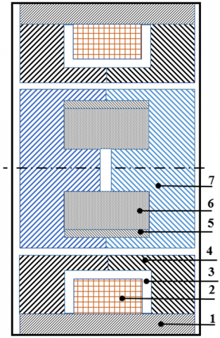
A modular single‑valve element (single port) was designed first and later tiled into a 2 × 2 arrangement to create a 4/3 directional valve. The single element comprises an outer steel ring, a central core, a cylindrical NdFeB permanent magnet, a copper coil (bobbin and winding), and a non-magnetic spacer that defines the active fluid gap. Key dimensions used throughout this study are summarized in Table 1. The valve was intentionally sized to be compact (diameter ≈38 mm, width ≈40 mm) to demonstrate feasibility for small hydraulic systems, as shown in Figure 1.
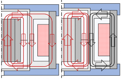
Figure 2 illustrates the path and direction of the magnetic field of the proposed MR valve. Only the permanent magnet is shown in Figure 2. The magnetic field of the permanent magnet passes through the valve casing, the valve core, the permanent magnet, and other magnetic materials, forming a completely closed loop. The permanent magnet and the activated excitation coil simultaneously create a magnetic field, reducing the effect of the perpendicular magnetic flux density in the active gap region, thus forming a completely open loop. The magnetic circuit can be divided into several segments of magnetic resistance produced by the magnetic circuit in different materials and positions under the magnetic induction line.
Figure 1. FEMM program screenshot of the model design for the proposed MR valve. (1) is the outer ring of the valve, (2) is the coil, (3) is the coil bobbin, (4) is the outer core of the valve, (5) is the non-magnetic ring, (6) is the permanent magnet, and (7) is the inner core of the valve
Table 1. Design summary representative
|
Valve Items Description |
Value |
|
Diameter |
38 mm |
|
Width |
40 mm |
|
Coil inner diameter |
25 mm |
|
Coil turns |
50 |
|
Coil wire diameter |
≈ 0.315 mm |
|
Magnet grade |
NdFeB (approx. 40 MGOe) |
|
Active gap width |
1 mm |
|
Gap axial length |
4 mm |
|
Magnet outer / inner diameters |
14 mm / 4mm |
|
Magnet length |
12 mm |
2.2 Electromagnetic analysis (FEMM)
To verify the feasibility of the design of a permanent magnet MR valve, the proposed dimensions are shown in Figure 1. The magnetic field of the permanent MR valve was simulated and analyzed using the finite element method with the open-source Finite Element Method Magnetics (FEMM software). Based on the structure symmetry, it was transformed into a two-dimensional plane. Since its cross-section is a regular axial shape, half of the cross-section is chosen as the simulation object without affecting the accuracy of the model solution.
FEMM 2D simulations were used to compute magnetic flux density (B) distributions for two operating cases: permanent magnet only (coil unenergized, I = 0 A); and coil energized with current that partially or fully cancels the field in the active gap (counter‑acting polarity).
FEMM was chosen for its suitability for axisymmetric and 2D planar problems and for quick parametric sweeps of coil current. The simulations extracted B ⟂ (the component perpendicular to the flow path) in the active gap regions to determine the MR yield stress. Figure 3 illustrates how to obtain the magnetic field inside the valve gap in the presence of a permanent magnet and shows the influence of the current supplied to the coil. In this proposed design for a permanent MR valve, the rheological magnetic fluid MRF-J25T was chosen as the valve's operating fluid. The τ-B curve—the relationship between the magnetic flux intensity of the MRF-J25T magnetic fluid and the shear stress—was derived and used in analysis software according to Eq. (1), a modification of the equation published in the study [9].
$\tau_y=C_1-C_2 B+C_3 B^2-C_4 B^3+C_5 B^4$ (1)
where, C1, C2, C3, C4, and C5 are 1.49834, 37.6018, 1102.1, 2046.42, and 1085.56, respectively.
Figure 2. The path and direction of the magnetic field of the relief MR valve: when the permanent magnet is effective only (left) and when the electromagnetic is effective to cancel the permanent magnet effect (right)
2.3 Constitutive model and pressure‑drop formulation
In this work, detailed closed-form expressions dependent on the exact geometry (annular, disc, or meandering channels) were computed following the methodologies in studies [2-4]. Additionally, these formulations were applied for annular/radial and “mosquito‑coil‑plate” style channels. MR fluids exhibit a strong dependence of yield stress (and apparent viscosity) on magnetic flux density, up to a saturation point [11, 12]. The yield stress (and hence the apparent flow resistance) increases with B until magnetic saturation, beyond which further increases in B produce negligible additional yield stress.
A Bingham‑type model was adopted to represent MR fluid shear behavior in the valve gap:
$\tau=\tau_y(B)+\mu \dot{\gamma}, \tau>\tau_y(B)$ (2)
where, τ is shear stress, $\tau_y(B)$ is the field‑dependent yield stress (stress generated at the liquid flow channel, which rises with B and saturates at high B), η is the zero‑field (carrier) viscosity, and is the shear rate.
Figure 3. FEMM program screenshot for the proposed model elements and materials (upper), and auto mesh generation (lower)
A pressure drop in the hole-shaped area is:
$\Delta P_{\text {hole }}=\frac{8 L_x}{\pi r_x^4} \mu Q$ (3)
where, L, r, and Q are the flow channel length (i.e., length of the round ring-shaped), the half diameter of the channel (i.e., the inner radius of the disk of the round ring-shaped), and the fluid discharge flow rate, respectively.
The drop in pressure in the disk area is:
$\Delta P_{d i s k}=\frac{6 \mu Q}{\pi H_x^3} \ln \left(\frac{R}{r}\right)$ (4)
where, R and H are the outer radius of the disc and the gap width of the effective fluid flow channel, respectively. Consequently, a yield‑stress pressure drop at the round, ring-shaped area is:
$\Delta P_{\text {yield }}\left(Q, \tau_y(B)\right)=\frac{6 L_x}{\pi r_x H^3} \mu Q$ (5)
The viscous pressure drop, using the approximation function, can be written as:
$\Delta P_{v i s c o u s}(Q)=C \frac{\Delta L_x}{g} \tau_y(B)$ (6)
ΔL and g are the length of the effective fluid flow channel and the acceleration due to gravity, respectively. C is the coefficient obtained by calculating the ratio between the field-dependent pressure drop and viscous pressure drop.
The total pressure drop ΔP across the valve is the sum of a viscous term and a yield‑stress term, each of which depends on geometry and Q:
$\Delta P(Q, B)=\Delta P_{{viscous }}(Q)+\Delta P_{ {yield }}\left(Q, \tau_y(B)\right)$ (7)
2.4 Prototype fabrication and experimental setup
A single-valve prototype (one single-valve element) was machined and assembled according to the design shown in Figure 1, with the materials illustrated in Table 2. The rheological magnetic fluid (MRF-J25T) was chosen as the valve's operating fluid, using the materials and specifications listed in Table 3. The test rig consisted of a hydraulic gear pump, a reservoir with MR fluid, pressure gauges, a flowmeter, a test valve, and a single‑acting cylinder. The coil current was controlled by a programmable current source while pressure and flow were logged for steady flow setpoints. Temperature was monitored to avoid thermal drift.
Table 2. Parts of the proposed MR valve, including one strong magnet (NdFeB (approx. 40 MGOe))
|
Item |
Description |
Material |
Quantity |
|
1 |
Valve Outer Ring |
Steel 1006 |
1 |
|
2 |
Coil |
Copper |
1 |
|
3 |
Coil Bobbin |
Plastics |
1 |
|
4 |
Valve Outer Core |
Steel 1006 |
2 |
|
5 |
Non-magnetic Ring |
Aluminum 1100 |
1 |
|
6 |
Valve Inner Core |
Steel 1006 |
2 |
Table 3. Specifications of MRF-J25T [9]
|
MRF Parameters |
Value |
|
Ferromagnetic particles to fluid volume ratio |
25% |
|
Career fluid |
Hydrocarbon oil |
|
MRF density |
2.65 g/m3 |
|
Viscosity without a magnetic field |
0.8 Pa.s |
|
MRF Shear stress |
> 50 kPa |
|
Operating temperature |
-25~130℃ |
Four single‑valve elements were arranged in a planar quadrilateral so that the assembly provides four working ports and one return to tank—functionally equivalent to a conventional 4/3 hydraulic directional valve, as shown in Figure 4. FEMM simulations examined magnetic interaction between adjacent single valves for three cases: all coils unenergized (permanent magnet only)—all sub‑valves closed; one coil energized at operational current (≈ 0.7 A) with adjacent valves unenergized—local opening observed, minimal interference; and multiple non‑adjacent coils energized to produce directional flow routing—the assembly functioned as a directional valve with negligible magnetic cross‑talk for the chosen spacing.
These results indicate that, with the proposed geometry and spacing, the permanent magnet closure with a small opposing coil current scheme is practical for an assembled directional valve without problematic magnetic interference.
Figure 4. FEMM program of the hydraulic directional-valve design and its working principle
4.1 Magnetic field distributions
FEMM contour plots in Figures 5, 6, and 7 show that the permanent magnet produces B ⊥ in the active gap up to approximately 0.4–0.6 T in the proposed geometry (peak values depend on magnet grade, air gaps, and steel reluctance paths). Energizing the coil with the selected polarity and amplitude reduces B ⊥ in the gap; at about 0.68–0.70 A in this design, the net perpendicular component in the active gap tends to zero in the 2D simulation, which corresponds to a practical opening condition. The current was adjusted to eliminate the magnetic field effect in the effective gap. Magnetic flux values (B), specifically the component perpendicular to the MR fluid's flow, were measured in the fluid path and gaps for different current levels. It can be confirmed that these figures depict the cases of maximum current (which registered no field effect) and no current, as well as how magnetic flux values varied as a function of applied current.
Figure 5. FEMM program screenshot for magnetic values inside the gap with a permanent magnet (upper) and values of the magnetic field inside the gap without a permanent magnet (lower)
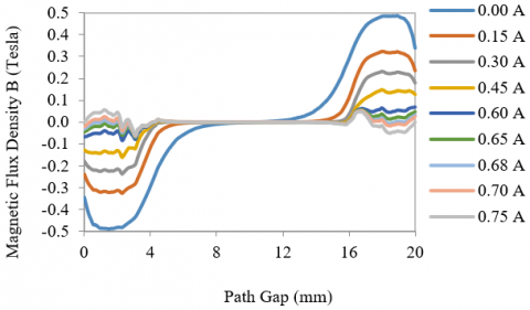
Figure 6. Magnetic density values along the MR valve gap path with different currents
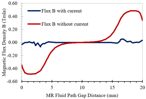
Figure 7. Magnetic density values along MR valve gap path with and without applied current
Since only the perpendicular magnetic flux affects valve operation, parallel values are not considered in the calculations. Figures 6 and 7 show how the magnetic flux is very inhomogeneous within the valve's active regions—the first and last 4 mm of the fluid path. Specifically, with no electrical current and with a current of 0.7 A. The magnetic flux is high at zero electrical current, peaking around 0.5 Tesla. This value was used for the calculations because the fluid's viscosity does not increase beyond this point according to its specifications. While with a current of 0.7 A, the magnetic flux drops tend to zero. This particular current was chosen because higher currents would create an opposing effect, causing the magnetic flux to move away from zero again, as shown in Figure 6. The 12mm middle section of the fluid path is ineffective because the magnetic flux is perpendicular to the fluid flow in that region, and therefore has no effect on the valve's operation.
4.2 Pressure‑flow behaviour and coil thresholds
Using the Bingham formulation and the FEMM‑predicted B→τy mapping (from manufacturer data and published correlations), pressure–flow curves were computed for currents from 0 to 0.7 A [13-16]. The computed results show a high pressure drop at I equals 0 A (closed) and a very low pressure drop for (I) equals 0.68 to 0.70 A (open) at low Q, consistent with prototype measurements. Experimental steady‑state points (open circles) are plotted on the computed curves and show good agreement within experimental uncertainty.
Theoretical calculations, based on magnetic data from a single-valve analysis, were performed using Eqs. (2) through (7) to determine the pressure-flow relationship for various current conditions.
Figure 8 shows that the valve is completely closed and operating with high pressure for current values from 0 to 0.65 A. Conversely, for currents between 0.6 and 0.7 A, the pressure is very low or nonexistent, indicating an open valve that allows fluid to pass.
Figure 8. The relation between the total pressure drop and flow rate of MR valve at different currents
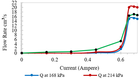
Based on these results, the current was set to 0 A, where the high-pressure closed valve state is maintained by the permanent magnet effect, and to 0.68 and 0.7 A, where the open valve state is maintained. These values were chosen because they represent the extremes of the valve's operational range. Further details of the current-flux relationship were shown in Figure 7. The chosen pressure values of 168 and 214 kPa were derived from the relationships in Figure 8. Also, the magnetic flux is approximately 0.5 Tesla at 0.68 and 0.7A.
Magnetic flux values, calculated for pressures of 168 and 214 kPa, were found to change with the current in the coil. The magnetic flux initially showed a gradual, near-linear increase with current from 0 to about 0.6A, then increased sharply between 0.6 and 0.65A. It remained relatively constant from 0.65 to 0.7A, which was determined to be the optimal range before the effect reversed.
4.3 Directional operation
The 2 × 2 assembly was tested in simulation for the set of coil excitations that route flow between the four ports. Results show that by energizing non‑adjacent coils, the assembly can route flow in multiple directions while keeping other sub‑valves closed. Prototype bench tests with sequential coil switching confirmed directional switching behaviour.
To validate the valve's operation, a prototype based on the mechanical design was built and tested using a hydraulic system (Figure 9). This system includes a hydraulic gear pump, an MR fluid tank, the MR valve, and a single-acting cylinder. The cylinder of the hydraulic actuator was tested for upward and downward motion, and the volumetric flow rate was measured at different coil currents while maintaining constant pressure at the pressure gauges. Based on this, a flow rate vs. current relationship was established (Figure 10). An analysis revealed an approximate operating pressure of 180 kPa, which falls within the desired range, confirming proper valve operation.
Also, the four-valve directional control valve was modeled by simulating the magnetic field of its four segments at zero current. There was no magnetic interference between the adjacent valves, i.e., they were closed. One valve at zero current and one adjacent valve at full current (0.7 A) were also tested, again showing no interference; the valve at zero current was closed, and the adjacent valve was open. This made the four-valve setup perform like a directional valve, even at current-switching operations.
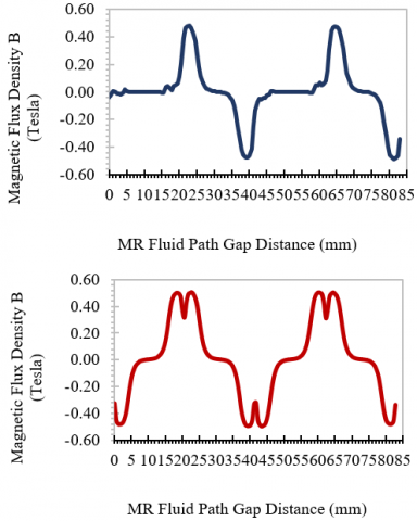
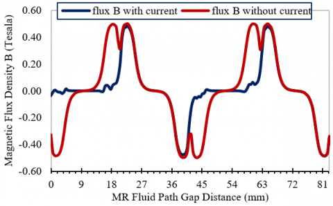
The culmination of this research is detailed in Figures 11-13 that visualize the valve's functionality. Figure 10 presents changes in the directional fluid flow achieved through the four valve ports. Figure 12 further demonstrates this by showing the magnetic flux distribution, highlighting the maximum field (0.5 Tesla) in the activated valve gaps and near-zero flux in the others. Specifically, Figure 12 (upper) shows the magnetic field pattern when two non-adjacent valves are energized, while Figure 12 (lower) shows the state when all coils are de-energized. Figure 13 provides a comparative view of these conditions, showcasing the difference in magnetic field distribution that enables the valve's directional control.
The possibility provided by this research made the utilization of MR valve-related systems, particularly those that require high control to improve performance, response speed, and tracking, possible. In future studies, high-performance MR directional control valve design will be conducted based on sophisticated control methods, such as active disturbance rejection control, to effectively manage system disturbances and improve response speed and tracking performance [17-20].
The outcomes of this work, particularly those related to key variables such as flow rate and pressure drop, can be used to validate analytical models or improve simulations of complex MR phenomena, especially those using an efficient computational approach for the design and analysis of magnetic resonance valves, such as the Casson fluid model and the Crank-Nicholson methodology applied in the study [21]. This also confirms the reliability of the advanced computational approach used in this study across a wide range of MR device designs.
Figure 9. MR fluid power pack and system test of MR valve
Although there are limitations that may have a natural impact on what has been described in this study, such as demagnetization of the permanent magnet over time or temperature effects on the MR fluid. Actually, the permanent magnet in the valve is completely unaffected by heat, since the valve generates no significant heat and consumes very little energy only when it is opened. Consequently, there are no elevated temperatures to disrupt the magnetic domains, which reduces the overall magnetic field strength. Also, there are no external magnetic fields to partially or completely demagnetize a permanent magnet by realigning its internal domains. The physical shock and vibration, probability of corrosion, and time effect (natural aging) that can physically disorient magnetic domains and lead to a loss of field strength are out of scope for this paper, and these effects may be studied in future research.
Figure 10. Relation between the flow rate and operating current of MR valve at the allowed pressure drop
Figure 11. FEMM program screenshot for magnetic density of MR directional valve in three different cases of operation
Figure 12. The values of magnetic flux density along the MR fluid path gap. Opening of the MR directional valve with current (upper) and closing of the MR directional valve without current (lower)
The explicit objective of this study — to design and demonstrate a 4/3 MR directional valve that is normally closed by a permanent magnet and opens proportionally with a small opposing coil current — has been met at the design and prototype levels. The Finite Element Method for Magnetics (FEMM) is used to solve for magnetic flux density distributions of both permanent magnets separately and in conjunction with coil excitation. To model the pressure, drop in MR fluids, a Bingham-type constitutive model was used to separate viscous and yield-stress components. The validation of these computational models and the performance of the proposed directional valve were subsequently confirmed through the fabrication of a prototype and a detailed experimental investigation of its assembly and interaction effects.
FEMM simulations and prototype tests indicate that a strong NdFeB magnet can produce sufficient perpendicular flux in the active gap to close the valve without coil current, and that a small counter‑polarity coil current (≈0.68–0.70 A for the present geometry and coil winding) can neutralize the gap flux to open the valve. Furthermore, the permanent magnet + small‑coil approach reduces continuous power needs compared to designs that require sustained coil current to hold the valve closed, thereby reducing heating and potentially extending service life.
This valve, which is permanently magnetized, is a normally closed valve that can proportionally be opened by an electric current flowing through its coil. This provides variable flow control through the size of the opening. The valve size is proportionate to its intended application, and the design procedure can be altered to create valves of varying sizes for various applications. It can also be used as a simple on-off valve. This is a novel concept, as it visualizes a facet that has not typically been studied in previous research.
A major advantage of this design is its lower peak electrical current consumption compared to previous technologies. This will reduce heat generation, a topic of future development. Furthermore, opening the valve requires only an electrical current; the permanent magnet maintains the closed position without using energy. This is in contrast to conventional hydraulic valves, both digital and non-digital (without permanent magnets), which typically require a constant current to remain closed, which can cause them to overheat, and then affect fluid properties. Regarding response time, the proposed valve is no different from most other presented designs by previous works, regardless of whether it has a permanent magnet or not. The power consumption of this valve is primarily dependent on the permanent magnet, which does not require electrical power. The valve only requires electrical power to open, unlike valves that work with no permanent magnet, which rely directly and continuously on a supplied electrical power supply. Additionally, the highest power consumption is 8.4 W when the proposed valve is open. While most other designs that do not use a permanent magnet range between 24 and 36 W and operate continuously.
Figure 13. The values of magnetic flux density along the MR fluid path gap for the MR directional valve with and without the presence of the electric current
The four-valve arrangement is a proportional directional control valve. It is a new application of permanent magnets, where current distribution among non-adjacent valves allows for varied and adjustable direction control. This paper sets the stage for further innovation in valve design, including investigations into flow relief and control valves. The findings are particularly significant for single-phase valves, such as dampers in most devices, and hold potential benefits in medical devices, like prosthetic limbs and patient-handling equipment, by improving efficiency through the assistance of MR fluids.
The authors gratefully acknowledge the use of the control Lab at Universiti Sains Malaysia (USM).
|
B |
Magnetic flux density |
|
DC |
Direct current, Ampere |
|
FEMM |
Finite Element Method for Magnetics |
|
G |
Acceleration due to gravity, m. s-2 |
|
MR |
Magnetorheological |
|
Greek symbols |
|
|
τ |
Shear stress, Pa (N. m-2) |
|
µ |
Zero-field viscosity, kg. m-1. s-1 |
|
Subscripts |
|
|
x |
Flow channel |
|
y |
The yield point |
[1] Shiao, Y., Gadde, P., Kantipudi, M.B. (2022). Energy-saving actuation signal for magnetorheological valve train by leveraging hysteresis effect. Energy Conversion and Management: X, 16: 100292. https://doi.org/10.1016/j.ecmx.2022.100292
[2] Ren, J., Zhou, F., Wang, N., Hu, G. (2022). Multi-objective optimization design and dynamic performance analysis of an enhanced radial magnetorheological valve with both annular and radial flow paths. Actuators, 11(5): 120. https://doi.org/10.3390/act11050120
[3] Prabhakara, H.A., Imaduddin, F., Bahiuddin, I., As’arry, A., Ismail, A.A., Mazlan, S.A. (2025). An innovative method for predicting parametric dependent-pressure drops of meandering magnetorheological valves using deep neural networks. Scientia Iranica. https://doi.org/10.24200/sci.2025.65007.9243
[4] Hu, G., Qi, H., Zheng, K., Yu, L. (2022). Design and performance evaluation of a magnetorheological valve with mosquito-coil-plate fluid flow channels. Sensors and Actuators A: Physical, 347: 113983. https://doi.org/10.1016/j.sna.2022.113983
[5] Ntella, S.L., Thabuis, A., Tiwari, B., Jeanmonod, K., Koechli, C., Perriard, Y. (2023). Highly efficient miniaturized magnetorheological valves using electropermanent magnets. IEEE Robotics and Automation Letters, 8(3): 1487-1494. https://doi.org/10.1109/LRA.2023.3238669
[6] Ebrahim Pourshayan, A., Rabbani, A., Farahani, S., Rabbani, Y., Ahmadi Danesh Ashtian, H., Shariat, M., Nejad, Gh., Emami Satellou, A.A. (2021). Modeling and simulation of the magnetorheological fluid sleeve valve. Iranian Journal of Chemical Engineering, 18(1): 25-35. https://doi.org/10.22034/ijche.2021.131248
[7] Liu, Y., Yang, X., Li, D., Xie, G. (2023). Study on the structural design and performance of magnetorheological (MR) valve with hybrid supply magnetic source and double annular channels. Journal of Magnetism and Magnetic Materials, 570: 170506. https://doi.org/10.1016/j.jmmm.2023.170506
[8] Zhu, Y., Yan, R., Liu, D., Deng, X., Yao, J. (2023). Investigation of a new vibration-absorbing roller cage shoe with a magnetorheological damper in mine hoisting systems. Applied Sciences, 13(22): 12506. https://doi.org/10.3390/app132212506
[9] Salloom, M.Y., Almuhanna, M.Y. (2025). Design and analysis of magneto-rheological relief valve using a permanent magnet. Advances in Science and Technology Research Journal, 19(1): 243-255. https://doi.org/10.12913/22998624/195494
[10] Salloom, M.Y., Almuhanna, M.Y. (2024). Analysis of the improved proportional hydraulic directional control valve by adding a solenoid directional valve. Journal Européen des Systèmes Automatisés, 57(1): 105-115. https://doi.org/10.18280/jesa.570111
[11] Kumar, J.S., Alex, D.G., Sam, P.P. (2020). Synthesis of magnetorheological fluid compositions for valve mode operation. Materials Today: Proceedings, 22(4): 1870-1877. https://doi.org/10.1016/j.matpr.2020.03.086
[12] Khan, S.A., Suresh, A., Seetharamaiah, N. (2014). Principles, characteristics and applications of magneto rheological fluid damper in flow and shear mode. Procedia Materials Science, 6: 1547-1556. https://doi.org/10.1016/j.mspro.2014.07.136
[13] Aposporidis, A., Haber, E., Olshanskii, M.A., Veneziani, A. (2011). A mixed formulation of the Bingham fluid flow problem: Analysis and numerical solution. Computer Methods in Applied Mechanics and Engineering, 200(29-32): 2434-2446. https://doi.org/10.1016/j.cma.2011.04.004
[14] Thampy, T., Rivington, E.G.R., Chandrashekar, R. (2022). Optimization of proportional solenoid for flow control valve using recursive method in OCTAVE and FEMM. Journal of Engineering Research and Sciences, 1(5): 61-70. https://doi.org/10.55708/js0105007
[15] Toluwaloju, T., Thein, C.K., Halim, D. (2022). Finite element simulation for predicting the magnetic flux density for electromagnetic vibration energy harvester. Engineering Proceedings, 27(1): 13341. https://doi.org/10.3390/ecsa-9-13341
[16] Kamal H.A., Salloom, M.Y. (2021). Analysis of magnetorheological normally close directional control valve. Al-Khwarizmi Engineering Journal, 17(4): 12-22. https://doi.org/10.22153/kej.2021.12.005
[17] Dahnoun, I., Bourek, A., Ammar, A., Belaroussi, O. (2024). Active disturbance rejection control based sensorless model predictive control for PMSM. Journal Européen des Systèmes Automatisés, 57(1): 117-125. https://doi.org/10.18280/jesa.570112
[18] Ismael, M.K., Bahar, S.T., Abdullah, A.A. (2025). Harmonic elimination method for permanent magnet synchronous motor utilizing active disturbance rejection control. Proceedings of Engineering and Technology Innovation, 30(1): 14386. https://doi.org/10.46604/peti.2024.14386
[19] Lin, S., Cao, Y., Li, C., Wang, Z., Shi, T., Xia, C. (2023). Two-degree-of-freedom active disturbance rejection current control for permanent magnet synchronous motors. IEEE Transactions on Power Electronics, 38(3): 3640-3652. https://doi.org/10.1109/TPEL.2022.3220565
[20] Harkat, A.R., Barazane, L., Larabi, A., Loukriz, A., Bendib, A. (2025). Advanced adaptive nonlinear control with deadbeat observer for permanent magnet synchronous motor drives. Journal Européen des Systèmes Automatisés, 58(3): 479-491. https://doi.org/10.18280/jesa.580306
[21] Sharma, B.K., Gandhi, R., Abbas, T., Bhatti, M.M. (2023). Magnetohydrodynamics hemodynamics hybrid nanofluid flow through inclined stenotic artery. Applied Mathematics and Mechanics, 44(3): 459-476. https://doi.org/10.1007/s10483-023-2961-7