Mustapha Koriker*![]() | Mahmoud Drif
| Mahmoud Drif![]() | Djamel Saigaa
| Djamel Saigaa![]() | Abdelouadoud Loukriz
| Abdelouadoud Loukriz![]()
© 2025 The authors. This article is published by IIETA and is licensed under the CC BY 4.0 license (http://creativecommons.org/licenses/by/4.0/).
OPEN ACCESS
Batteries are crucial for transitioning to sustainable energy, with lead-acid batteries currently offering the most cost-effective solution. Accurate battery modeling is vital for simulating renewable energy systems and developing model-based battery management systems (BMS). We propose a novel electrical model for lead–acid batteries based on a three-branch equivalent circuit topology capable of dynamically representing charge, discharge, and overcharge modes within a unified framework. The innovation of this model lies in representing both the open-circuit voltage and internal resistance as controlled voltage sources, enabling adaptive and state-dependent behavior with respect to the state of charge and temperature. Moreover, thermal and ageing effects are integrated into a single dynamic structure, ensuring accurate simulation under variable operating conditions. The model is implemented in PSpice using Analog Behavioral Modeling (ABM) blocks, which facilitates efficient simulation and direct use in renewable energy system design. The proposed model exhibits mean bias error (MBE) and root mean square error (RMSE) values below 90 mV/cell and 70 mV/cell for charging, and below 100 mV/cell and 70 mV/cell for discharging. This model, compatible with simulation platforms like MATLAB/Simulink, PSIM, PSpice, and LabVIEW, serves as a potent tool for solving electrical circuit problems and equations accurately.
lead-acid battery, equivalent electrical circuit, SOC, PSpice, Tudor battery
Over the past decade, electricity consumption has significantly increased, prompting the exploration of alternative energy sources. Consequently, the use of renewable energy sources has become imperative due to environmental concerns and the need for sustainable energy solutions [1]. However, energy production through these environmentally friendly systems remains inefficient and heavily relies on fluctuating weather conditions. To address this challenge, it is necessary to integrate energy storage devices capable of maintaining energy levels in the event of potential interruptions from these renewable sources [2]. The effective solution to this dilemma lies in adopting lead-acid batteries [3, 4], which function as electrochemical systems capable of storing electrical energy in the form of chemical energy for later use [5]. Significant efforts have been made in the literature to develop models for these batteries over the past two decades, with the most commonly used model being the CIEMAT model [6, 7]. These models can be broadly categorized into four distinct types [8, 9]:
There are significant challenges in battery modelling due to the complex interaction of electrochemical processes, electrical behavior and external factors that influence battery performance. A major problem is the use of non-linear differential equations in chemical models, which leads to computational complexities and inaccuracies in the prediction of battery behavior. In addition, the existing models often neglect critical factors such as the recovery effect, where temporary improvements in performance after rest periods are not properly accounted for, affecting discharge rate predictions. In addition, composite electrical models may not account for the non-linear behavior of capacity, limiting their ability to accurately represent battery characteristics under varying conditions. Furthermore, mathematical models, while providing the abstraction and linearity required for analytical convenience, can oversimplify the complex electrochemistry of batteries, reducing the accuracy of predictions. Addressing these challenges requires the development of more sophisticated models that incorporate non-linearities, recovery effects and detailed electrochemical behaviors, as well as rigorous validation processes to ensure reliability in a variety of scenarios.
In this paper, we propose a novel electrical model for lead–acid batteries that ensures high accuracy and efficiency in representing their dynamic behavior under varying operating conditions. The model effectively captures the influence of charge and discharge states, temperature variations, and load changes, thus providing a comprehensive understanding of battery performance. Its structural and functional innovation lies in the introduction of a new circuit topology, where both the open-circuit voltage and the internal resistance are represented as controlled voltage sources. This formulation yields a more stable and mathematically consistent input–output relationship compared with conventional equivalent-circuit models. Moreover, the proposed model integrates thermal and ageing effects within a unified dynamic framework, allowing reliable simulation of battery behavior across different scenarios. Designed for compatibility with major simulation platforms such as MATLAB/Simulink, PSpice, PSIM, and LabVIEW, the model offers a robust, flexible, and experimentally validated tool for the analysis, design, and optimization of energy storage systems in renewable energy applications.
The rest of this paper is organized as follows. In Section 2, state-of-the-art in lead-acid battery modelling is briefly recalled. In Section 3, the proposed electrical model is developed, driven by the development of Lasnier, CIEMAT, Shepherd, and Macomber mathematical models. Implementation on PSpice platform is carry out in the Section 4. In the Section 5, the simulation of the proposed model. In order to validate the proposed model, an experimental validation is performed in the Section 6. Finally, conclusions are drawn in Section 7.
The lead-acid battery serves as a storage element in many electrical systems, storing energy in the form of chemical energy. The electrochemical reactions within the battery are described by the following Eq. (1) [7, 19]:
$\mathrm{PbO}_2+2 \mathrm{H}_2 \mathrm{SO}_4+\mathrm{Pb} \leftrightarrow 2 \mathrm{PbSO}_4+2 \mathrm{H}_2 \mathrm{O}$ (1)
Battery is an electrochemical device that stores energy in chemical form and later releases it in the form of electrical energy. In the models of Lasnier, CIEMAT, Shepherd and Macomber, the battery is described as consisting of an electromotive force (EMF) and a dynamic resistance. The electromotive force is represented by the battery open circuit voltage (VOC) and it depends on both the state of charge (SOC) and the temperature (T). On the other hand, the dynamic resistance (R) depends on the nominal capacity ($C_n$); charging or discharging current ($I_{{bat}}$), state of charge (SOC) and temperature (T).
In the Appendix, we present the mathematical expressions governing the well most battery models exist in literature.
3.1 Proposed general model
The proposed model represents a significant contribution to the understanding and prediction of the dynamic behaviour of solar-charged lead-acid batteries. The model has been developed as an equivalent electric circuit that can successfully mimic the dynamic and thermal behaviour of the battery under various operating conditions. As opposed to purely theoretical approaches, the novel model is immediately usable in widespread simulation software such as MATLAB/Simulink, PSpice, and PSIM and is an effective and practical means for battery behaviour analysis under charging, discharging, overcharging, and with thermal stress variations. Without adding complexity to standard built-in models, the model augments existing simulation libraries with a bespoke representation specifically designed for photovoltaic applications. This dual focus on both usability and accuracy makes the model not only a scientific success, but also a useful tool of significant worth to the optimization of photovoltaic system reliability and lifetime.
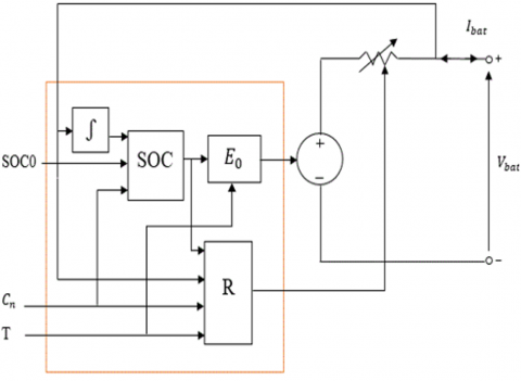
Figure 1 illustrates the general structure of a lead-acid battery, which includes the open-circuit voltage (VOC) and internal resistance (R), both electrical components represented by a controlled voltage source. In this case, the battery current is the primary input, while the nominal capacity, initial state of charge (SOC), and temperature are auxiliary inputs that regulate the battery's dynamic response. The battery voltage represents the model's output, the product of the interaction of these parameters.
This formulation enables the model to accurately simulate battery behavior under various loads and thermal conditions, through a simple, modular, and easy-to-simulate structure that can be implemented in most dynamic modeling environments.
Figure 1. Proposed general model of battery
As well-known in general relationship between the necessary elements of the battery, the output battery voltage is related to the open circuit voltage and the dynamic resistance. Therefore, the circuit voltage open VOC ($E_0$) is depending to the state of charge SOC and the battery temperature. Furthermore, the dynamic resistance (R) depends to the state of charge, temperature, nominal capacity, and battery temperature [7].
Based on the general relationship between the necessary elements of the battery discussed above, a general electrical model of the battery can be developed. Figure 1 shows the proposed general electrical model of the battery.
Note that:
$\mathrm{SOC}=\mathrm{F}\left(S O C_0, C_n\right), \mathrm{R}=\mathrm{G}\left(\mathrm{SOC}, \mathrm{T}, C_n\right)$ and $E_0=\mathrm{H}(\mathrm{SOC}, \mathrm{T})$.
3.2 Proposed three branches model
Since the battery can be divided into three distinct modes, each with its own mathematical model, the battery voltage in a general state is expressed by a piecewise defined Eq. (2). More precisely, when it comes to the charging phase, we apply the charging equation ($V_{c h}$), considering that the battery current is negative. On the other hand, during discharge, we use the discharge equation ($V_{dich}$) , under the condition that the current is positive. In the case of overcharge ($V_{overch}$), the current condition is negative, but the battery voltage remains above the threshold voltage ($V_{ref}$). This approach makes it possible to accurately and adaptively model the behaviour of the battery in different operational scenarios.
$V_{\text {bat }}= \begin{cases}V_{\text {dich}}, & \text { if } I \geq 0 \\ V_{c h}, & \text { if } I<0 \\ V_{\text {overch}}, & \text { if } I<0 \text { and } V_{\text {bat }}>V_{\text {ref}}\end{cases}$ (2)
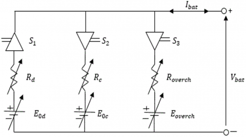
In this paper, a new electrical model for lead-acid batteries is proposed. This model comprises three branches (Figure 2), with each branch representing a specific case. The first branch pertains to the discharge mode, the second branch represents the charging mode, and the third branch addresses overloading. Each branch incorporates an open-circuit voltage (EO), a variable dynamic resistor (R), and a control diode. Each element of the proposed electrical model is explained in the Table 1.
Figure 2 illustrates the complete structure of the new model, composed of three distinct branches, each corresponding to an operating mode of the battery:
Branch 1 - Discharge mode: Comprises the open-circuit voltage $E_{0 d}$, the dynamic resistance $R_d$ and a switch $S_1$ that closes when the battery is in discharge mode.
Branch 2 - Charge mode: Comprises $E_{0 c}, R_c$, and the switch closes when the battery operates in charge mode.
Branch 3 - Overcharge mode: Comprises $E_{\text {overch}}, R_{\text {overch}}$ and the switch $S_3$ closes when the battery enters the overcharge mode.
The novelty of the new model lies in representing both the open-circuit voltage and internal resistance as controlled electrical elements, which is straightforward to implement in dynamic simulation tools such as MATLAB/Simulink, PSpice, PSIM, and LabVIEW.
This flexible and adaptive framework ensures that the model can precisely replicate the lead–acid battery behavior under all operating modes—including charge, discharge, and overcharge—with high computer efficiency and physical accuracy. This description neatly defines the proposed model and clearly distinguishes it from conventional equivalent circuit models (e.g., those of Copetti or Shepherd, etc.) by introducing a controllable, adaptive, and simulation-oriented approach that better represents the real dynamic behavior of lead–acid batteries.
Figure 2. The proposed electrical model
In the suggested electrical model, every circuit element has a clear physical interpretation related to definite internal processes of the lead–acid battery under various modes of operation. The open-circuit voltage ($E_0$) is the equilibrium potential between positive and negative electrodes, which is defined by the electrochemical condition of the active materials. It can be designated as $E_{0c}$ during charging, $E_{0d}$ during discharging, and $E_{overch}$ under overcharge conditions, considering variations in thermodynamic potential associated with electrode reactions and acid concentration gradients [20, 21].
The internal resistance (R) accounts for resistive cell behavior and considers charge-transfer kinetics, transport of ions in the electrolyte, and contact resistances. That is, $R_d$ is the charge-transfer resistance and diffusion losses during discharge, $R_c$.
The polarization and ion transport limitations during charging, and $R_{{overch}}$ the other parasitic responses such as gas evolution and side reactions on overcharging [22]. Such resistances are dynamically varying with state of charge, temperature, and level of degradation, thus creating a meaningful link between the circuit model and real electrochemical processes [23].
By making this electrochemical analogy, the model not only becomes more accurate but also more interpretable—imposing empirical circuit modeling and physicochemical understanding. This balance ensures the above model is both computationally efficient and physically valid for simulation, diagnostic, and optimization purposes in lead–acid battery systems.
Table 1 provides a detailed description of the elements constituting the proposed electrical model.
Table 1. Element of the proposed electric model
|
Branch |
Parameters of the Circuit Elements |
Nature of the Element |
|
Discharge Branch |
$S_1$ |
Controlled Diode |
|
$E_{0 d}$ |
Open circuit voltage |
|
|
$R_d$ |
Dynamic resistance |
|
|
Charge Branch |
$S_2$ |
Controlled Diode |
|
$E_{0 c}$ |
Open circuit voltage |
|
|
$R_c$ |
Dynamic resistance |
|
|
Overcharge Branch |
$S_3$ |
Controlled diode |
|
$E_{{overch}}$ |
Open circuit voltage |
|
|
$R_{{overch}}$ |
Overcharge resistance |
In this section, we explain how to calculate the battery voltage for the different modes:
Table 2 presents the logical conditions used to determine the control signals of the controlled diodes $\left(\mathrm{S}_1, \mathrm{~S}_2\right.$ and $\left.\mathrm{S}_3\right)$ as a function of the input parameters ($\mathrm{I}, V_{\text {bat}}$ and $V_{\text {ref}}$).
Table 2. Calculation of the control commands for the controlled diodes $\left(\mathrm{S}_1, \mathrm{~S}_2\right.$ and $\left.\mathrm{S}_3\right)$ from the values of the inputs (I, $V_{\text {bat}}$ and $V_{\text {ref}}$)
|
Input |
Output |
|||
|
I |
$V_{b a t}-V_{r e f}$ |
$S_1$ |
$S_2$ |
$S_3$ |
|
I≥0 |
Any value |
on |
off |
off |
|
I<0 |
<=0 |
off |
on |
off |
|
>0 |
off |
off |
on |
|
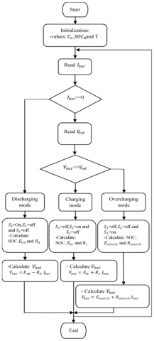
The flowchart presented in Figure 3 illustrates the different operational modes used for calculating the battery voltage.
Figure 3. Flowchart illustrating how the electrical model operates
The modelling of the lead-acid battery was carried out based on the model known as PSpice. This approach allowed the implementation of the electrical battery model. The proposed simulation was implemented in OrCAD PSpice Designer®, using the built-in Analog Behavioural Models (ABM) library along with conventional circuit components [24].
PSpice, which stands for "Personalized Simulation Program with Emphasis on Integrated Circuits," is an essential tool in the field of electrical engineering, especially when focusing on the design and simulation of integrated circuits. PSpice is one of the oldest simulation programs in the field of Analog and Digital circuits. In addition, it provides the ability to realistically perform accurate simulations of complex structures.
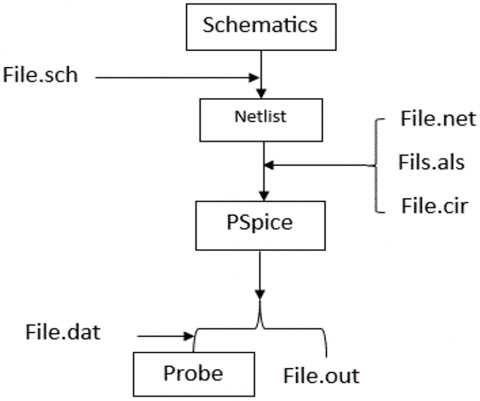
The PSpice software includes several modules as shown in the Figure 4.
Figure 4. Functional diagram of PSpice
PSpice has a special option: ABM (Analog Behavioral Modeling) which allows the use of synoptic blocks in simulations. This is one of its advantages, and it is an advantage that we exploit in our paper.
In the ABM library are functional blocks (mathematical and trigonometric functions, Laplace transform, correspondence table, etc.).
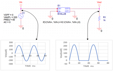
To illustrate, here is an example of Simple half-wave rectifier as shown in Figure 5. In this example the block contains the function (if) which works as a simple half-wave rectifier.
Figure 5. Simple half-wave rectifier by ABM
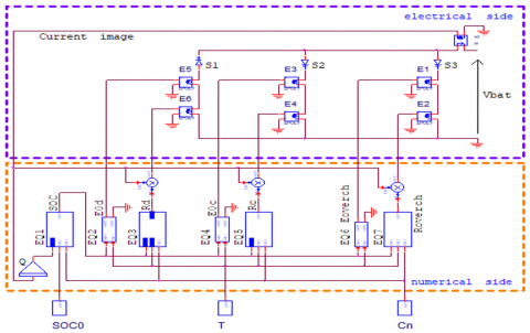
This study focuses on the implementation of models based on lead acid battery technologies. This is achieved by running the proposed model that relies on the battery circuit using oriented circuit simulations such as PSpice and others. This model is detailed in the diagram presented in Figure 6.
Figure 6 illustrates the equivalent electrical circuit of the proposed lead–acid battery model as implemented in PSpice.
Figure 6. Equivalent electrical diagram of the battery on PSpice
The model consists of two integrated parts, where the electrical part represents the electronic circuit of the acid battery. This part includes a controlled voltage source, which acts as a substitute for the open circuit voltage, as well as an internal dynamic resistor. As for the numerical part, it is mainly based on integrated mathematical functions.
Additional parameters such as temperature, rated capacity and initial state of charge are added to the digital part to improve the accuracy of battery information translation.
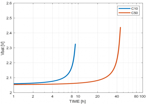
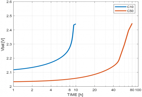
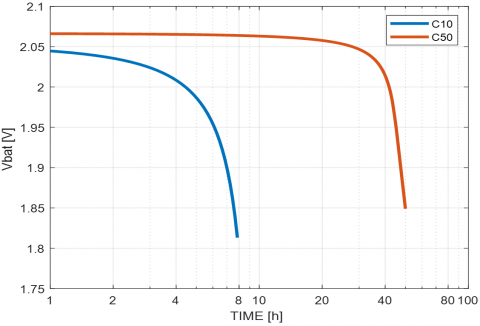
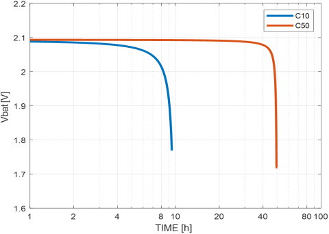
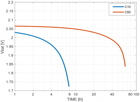
After presenting the electrical model, we perform simulations of the following mathematical models (Shepherd, Macomber, Lasnier and Copetti) in two cases (charge, overcharge) and discharge, we assume that the temperature is 25℃, the nominal capacity ($C_n=180 \mathrm{Ah}$), and the initial state of charge $\left(S O C_0=0.1\right)$. In discharging and (charging, overcharging) scenarios, the current is $\mathrm{I}=18 \mathrm{~A}\left(C_{10}\right)$ and $\mathrm{I}= 3.6 \mathrm{~A}\left(C_{50}\right)$.
As shown in Figure 7, the implementation of the proposed electrical model is carried out for Shepherd, Macomber, Lasnier and Copetti mathematical models in the charge case.
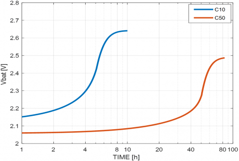
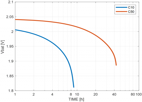
However, in Figure 8, the proposed electrical model is carried out in the case of battery discharge for each mathematical models such as Shepherd, Macomber, Lasnier and Copetti.
(a) Model Shepherd
(b) Model Macomber
(c) Model Copetti
(d) Model Lasnier
Figure 7. Proposed battery charging electrical models implemented in PSpice
(a) Model Shepherd
(b) Model Macomber
(c) Model Copetti
(d) Model Lasnier
Figure 8. Proposed battery discharging electrical models implemented in PSpice
To validate the developed electrical model wish is implemented in PSpice software, a comprehensive comparison was conducted between the real performance data of a singular lead-acid battery cell (Tudor C10 = 180 Ah, 2V) [25] that presented in the study [26] and the values predicted by the proposed electrical model implemented in PSpice software.
Noted that, during the charging process, the state of charge SOC fluctuated between 0.1 and 1, while during discharge, the state of charge varied from 1 to 0.1. For the temperature values, these experiments were conducted under standard test conditions at T = 25℃. In both scenarios, two values of current (I = 18 A and I = 3.6 A) A was applied to the battery to observe its behaviour and evaluate the predictions accuracy of the proposed electrical model implemented in PSpice.
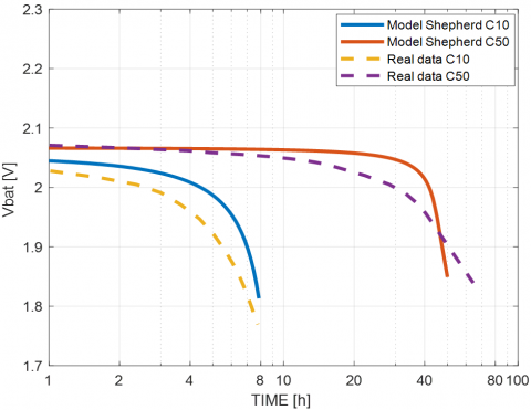
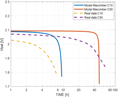
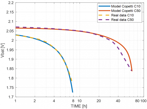
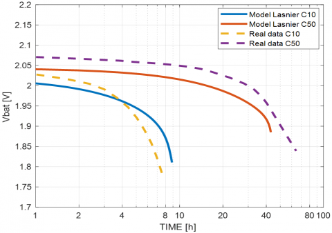
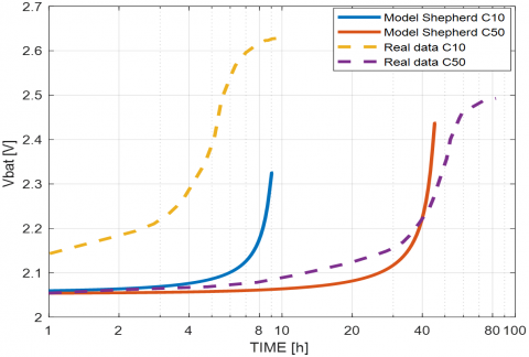
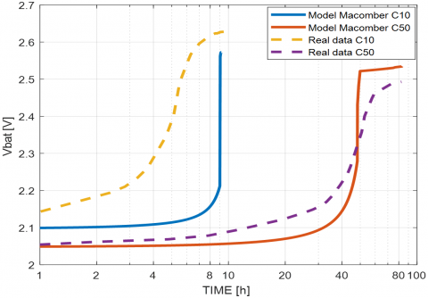
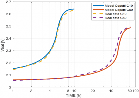
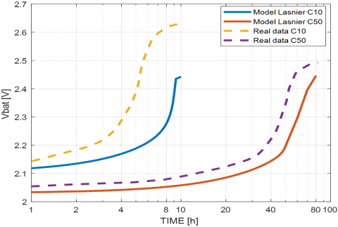
The Figure 9 present battery voltage comparison between real Tudor data and proposed electrical model driven by Shepherd, Macomber, Lasnier and Copetti mathematical models for battery discharge mode. Moreover, battery voltage comparison between real Tudor data and proposed electrical model driven by four mathematical models for battery charge mode is shown in Figure 10.
(a) Model Shepherd
(b) Model Macomber
(c) Model Copetti
(d) Model Lasnier
Figure 9. Battery voltage comparison between real Tudor data and proposed electrical model for battery discharge mode
(a) Model Shepherd
(b) Model Macomber
(c) Model Copetti
(d) Model Lasnier
Figure 10. Battery voltage comparison between real Tudor data and proposed electrical model for battery charge mode
In order to evaluate the effectiveness of the proposed electrical model, we calculated the Mean Bias Error (MBE) and RMSE between the real battery voltage data and the proposed electrical model voltage implemented in PSpice.
Table 3 and Table 4 give error calculation comparison between the real values and those given by the proposed electrical model.
Table 3. Error calculation comparison for each mode (Charge, discharge) for $\mathrm{I}\left(C_{10}\right)=18 \mathrm{~A}$
|
V/Cell |
Charge (V) |
Discharge (V) |
|
|
Copetti |
MBE |
0.0031 |
0.0012 |
|
RMSE |
0.0091 |
0.022 |
|
|
Shepherd |
MBE |
-0.099 |
-0.044 |
|
RMSE |
0.0103 |
0.028 |
|
|
Macomber |
MBE |
0.073 |
-0.038 |
|
RMSE |
0.053 |
0.018 |
|
|
Lasnier |
MBE |
-0.068 |
0.032 |
|
RMSE |
0.049 |
0.088 |
|
Table 4. Error calculation comparison for each mode (Charge, discharge) for $\mathrm{I}\left(C_{50}\right)=3.6 \mathrm{~A}$
|
V/Cell |
Charge (V) |
Discharge (V) |
|
|
Copetti |
MBE |
0.0041 |
-0.0032 |
|
RMSE |
0.0121 |
0.045 |
|
|
Shepherd |
MBE |
0.067 |
-0.033 |
|
RMSE |
0.064 |
0.021 |
|
|
Macomber |
MBE |
0.054 |
-0.027 |
|
RMSE |
0.037 |
0.014 |
|
|
Lasnier |
MBE |
-0.048 |
0.021 |
|
RMSE |
0.034 |
0.043 |
|
Table 3 and Table 4 present an analysis of the data provided for the proposed electrical model driven by four mathematical models and Tudor battery model. subjected to a charge and discharge current of (I = 18 A and I = 3.6 A). and at temperature of 25℃.
From these values. we observe that the MBE and RMSE values of the battery for these models were as follows:
It appears that the first mathematical model (Copetti) used for the proposed electrical model implemented in PSpice is the closest to representing the behaviour of the Tudor battery.
In this study, a novel electrical model for lead–acid batteries were developed to achieve a more accurate and physically meaningful representation of their dynamic behavior. The proposed model is based on a non-linear three-branch structure that employs controlled voltage sources and dynamic resistances to capture the battery’s behavior during charging. discharging. and overcharging operations within a unified framework. The model establishes explicit relationships between the open-circuit voltage (VOC). the dynamic internal resistance (R). and the controlled voltage source. enabling a consistent mathematical formulation of the battery’s input–output characteristics. Its implementation in common simulation platforms—MATLAB/Simulink. PSpice. PSIM. and LabVIEW—demonstrates both structural clarity and computational efficiency. Validation was carried out using experimental data from a Tudor C10 (2V. 180Ah) lead–acid cell and through comparison with well-established empirical formulations. including those of Copetti. Shepherd. Macomber. and Lasnier. The obtained results confirmed that the Copetti-based implementation within the proposed framework yielded the lowest MBE and RMSE values. demonstrating superior predictive capability under standard test conditions. Beyond numerical accuracy. the proposed model offers several practical advantages: it unifies multiple operating modes within a single structure. preserves computational simplicity. and provides a clearer link between electrical parameters and electrochemical processes. These characteristics make it a robust and versatile tool for the design. simulation. and optimization of lead–acid battery systems in renewable energy and storage applications.
Future work will focus on extending the model's validation to variable temperature conditions and different battery capacities. thereby further confirming its adaptability and reliability in real-world operational scenarios.
|
Model |
$V_{b a t}=\mathbf{E}_0 \pm \mathbf{R} \cdot I_{b a t}$ |
||
|
Discharge ($R=R_d$ and $E_0=E_{0 d}$) |
Charge ($\mathbf{R}=R_c$ and $\mathbf{E}_0=\mathbf{E}_{0 \mathrm{c}}$) |
Overcharge ($\mathbf{R}=\boldsymbol{R}_{{overch}}$ and $\mathbf{E}_0=\mathbf{E}_{{overch }}$) |
|
|
Copetti [6, 7, 25, 27] |
$\mathrm{E}_{0 \mathrm{~d}}=2.085-0.12(1-\mathrm{SOC})$ |
$\mathrm{E}_{0 \mathrm{c}}=2-0.16 . \mathrm{sOC}$ |
$\mathrm{V}_{\mathrm{ec}}=\left[2.45+2.011 \log \left(1+\frac{1}{\mathrm{C}^2}\right)\right](1-0.002 \Delta \mathrm{~T})$ |
|
$\mathrm{R}_{\mathrm{d}}=\frac{1}{\mathrm{Cn}}\left(\frac{4}{1+1^{1.3}}+\frac{0.27}{\operatorname{sOC}^{1.5}}+0.02\right)$ |
$\mathrm{R}_{\mathrm{c}}=\frac{1}{\mathrm{Cn}}\left(\frac{6}{1+\mathrm{I}^{0.86}}+\frac{0.48}{(1-\mathrm{SOC})^{1.2}}+0.036\right)$ |
$\mathrm{V}_{\mathrm{g}}=\left[2.24+1.97 \log \left(1+\frac{\mathrm{I}}{\mathrm{Cn}}\right)\right](1-0.002 \Delta \mathrm{~T})$ |
|
|
$(1-0.007 \Delta T)$ |
$(1-0.025 \Delta \mathrm{~T})$ |
$V_{\text {overch }}=\mathrm{V}_{\mathrm{g}}+\left(\mathrm{V}_{\mathrm{ec}}-\mathrm{V}_{\mathrm{g}}\right)\left(1-\operatorname{Exp}\left(\frac{\mathrm{t}_{\mathrm{g}}-\mathrm{t}}{\tau}\right)\right)$ |
|
|
Macomber [28-30] |
$\mathrm{E}_{0 \mathrm{~d}}=2.094(1-0.001 \Delta \mathrm{~T})$ |
$\mathrm{E}_{0 \mathrm{c}}=2.094(1-0.001 \Delta \mathrm{~T})$ |
$\mathrm{E}_{\text {overch }}=2.094(1-0.001 \Delta \mathrm{~T})$ |
|
$\mathrm{R}_{\mathrm{d}}=\frac{1}{\mathrm{C}_{\mathrm{n}}}\left(\frac{0.189}{\operatorname{soC}}-0.15(1-0.02 \Delta \mathrm{~T})\right)$ |
$R_c=\frac{1}{\mathrm{C}_{\mathrm{n}}}\left(\frac{0.189}{1.142-\mathrm{sOC}}-0.15(1-0.02 \Delta \mathrm{~T})\right)$ |
$R_{\text {overch }}=\frac{1}{c_n}\left(\frac{0.189}{1.142-S O C}-0.15(1-0.02 \Delta T)\right.$ |
|
|
|
|
$+(S O C-0.9) \log \left(\frac{300 . I}{C_n}+1\right)$ |
|
|
Lasnier [31, 32] |
$\mathrm{E}_{0 \mathrm{~d}}=1.926+0.124 . \operatorname{SOC}(t) . n_s$ |
$\mathrm{E}_{0 \mathrm{c}}=2+0 \cdot 148 \cdot \mathrm{SOC}(\mathrm{t})$ |
|
|
$\mathrm{R}_{\mathrm{d}}=\frac{0.19+\frac{0.1037}{\mathrm{SOC}(\mathrm{t})-0.14}}{\mathrm{SOC}_{\mathrm{m}}} n_S$ |
$\mathrm{R}_{\mathrm{c}}=\frac{0.758+\frac{0.1309}{1.06-\mathrm{SOC}(\mathrm{t})}}{\mathrm{SOC}_{\mathrm{m}}}$ |
|
|
|
Shepherd [28, 29, 33-36] |
$\mathrm{E}_{0 \mathrm{~d}}=\mathrm{E}_{\mathrm{s}}$ |
$\mathrm{E}_{0 \mathrm{c}}=\mathrm{E}_{\mathrm{s}}$ |
|
|
$R_d=K\left(\frac{Q}{Q-I . t}\right)+N$ |
$R_c=K\left(\frac{Q}{Q-I . t}\right)+N$ |
|
|
[1] Chen, S.X., Tseng, K.J., Choi, S.S. (2009). Modeling of lithium-ion battery for energy storage system simulation. In 2009 Asia-Pacific Power and Energy Engineering Conference, Wuhan, China, pp. 1-4. https://doi.org/10.1109/appeec.2009.4918501
[2] Aurilio, G., Gallo, D., Landi, C., Luiso, M., Rosano, A., Landi, M., Paciello, V. (2015). A battery equivalent-circuit model and an advanced technique for parameter estimation. In 2015 IEEE International Instrumentation and Measurement Technology Conference (I2MTC) Proceedings, Pisa, Italy, pp. 1705-1710. https://doi.org/10.1109/i2mtc.2015.7151537
[3] Loukil, J., Masmoudi, F., Derbel, N. (2016). Modeling of internal parameters of a lead acid battery with experimental validation. In 2016 13th International Multi-Conference on Systems, Signals and Devices (SSD), Leipzig, Germany, pp. 478-483. https://doi.org/10.1109/ssd.2016.7473738
[4] Divya, K.C., Østergaard, J. (2009). Battery energy storage technology for power systems—An overview. Electric Power Systems Research, 79(4): 511-520. https://doi.org/10.1016/j.epsr.2008.09.017
[5] Jantharamin, N., Zhang, L. (2008). A new dynamic model for lead-acid batteries. In 4th IET International Conference on Power Electronics, Machines and Drives (PEMD 2008), York, United Kingdom, pp. 86-90. https://doi.org/10.1049/cp:20080488
[6] Copetti, J.B., Lorenzo, E., Chenlo, F. (1993). A general battery model for PV system simulation. Progress in Photovoltaics: Research and Applications, 1(4): 283-292. https://doi.org/10.1002/pip.4670010405
[7] Achaibou, N., Haddadi, M., Malek, A. (2008). Lead acid batteries simulation including experimental validation. Journal of Power Sources, 185(2): 1484-1491. https://doi.org/10.1016/j.jpowsour.2008.06.059
[8] Khattak, A.A., Khan, A.N., Safdar, M., Basit, A., Zaffar, N.A. (2020). A hybrid electric circuit battery model capturing dynamic battery characteristics. In 2020 IEEE Kansas Power and Energy Conference (KPEC), Manhattan, USA, pp. 1-6. https://doi.org/10.1109/kpec47870.2020.9167659
[9] Gallo, D., Landi, C., Luiso, M., Rosano, A. (2013). Experimental validation of mathematical models of storage systems for smart grids. In 2013 IEEE International Workshop on Applied Measurements for Power Systems (AMPS), Aachen, Germany, pp. 126-131. https://doi.org/10.1109/amps.2013.6656238
[10] Tremblay, O., Dessaint, L.A., Dekkiche, A.I. (2007). A generic battery model for the dynamic simulation of hybrid electric vehicles. In 2007 IEEE Vehicle Power and Propulsion Conference, Arlington, USA, pp. 284-289. https://doi.org/10.1109/vppc.2007.4544139
[11] Schmidt, A.P., Bitzer, M., Imre, Á.W., Guzzella, L. (2010). Experiment-driven electrochemical modeling and systematic parameterization for a lithium-ion battery cell. Journal of Power Sources, 195(15): 5071-5080. https://doi.org/10.1016/j.jpowsour.2010.02.029
[12] Dominko, R., Bele, M., Gaberšček, M., Meden, A., Remškar, M., Jamnik, J. (2006). Structure and electrochemical performance of Li2MnSiO4 and Li2FeSiO4 as potential Li-battery cathode materials. Electrochemistry Communications, 8(2): 217-222. https://doi.org/10.1016/j.elecom.2005.11.010
[13] Bhat, C., Channegowda, J., Naraharisetti, K. (2022). An improved equivalent circuit parameter estimation using electrochemical model for lead-acid battery. In 2022 IEEE Delhi Section Conference (DELCON), New Delhi, India, pp. 1-4. https://doi.org/10.1109/delcon54057.2022.9753635
[14] Zheglov, V., Gao, W., Muljadi, E., Wang, G. (2009). A new control strategy for stand-alone fuel cell-battery hybrid power supply system. In 2009 IEEE Power and Energy Society General Meeting, Calgary, Canada, pp. 1-6. https://doi.org/10.1109/PES.2009.5275277.
[15] Li, S., Ke, B. (2011). Study of battery modeling using mathematical and circuit oriented approaches. In 2011 IEEE Power and Energy Society General Meetin, Detroit, USA, pp. 1-8. https://doi.org/10.1109/pes.2011.6039230
[16] Ghossein, N.E., Salameh, J.P., Karami, N., Hassan, M. E., Najjar, M.B. (2015). Survey on electrical modeling methods applied on different battery types. In 2015 Third International Conference on Technological Advances in Electrical, Electronics and Computer Engineering (TAEECE), Beirut, Lebanon, pp. 39-44. https://doi.org/10.1109/taeece.2015.7113597
[17] Dürr, M., Cruden, A., Gair, S., McDonald, J.R. (2006). Dynamic model of a lead acid battery for use in a domestic fuel cell system. Journal of Power Sources, 161(2): 1400-1411. https://doi.org/10.1016/j.jpowsour.2005.12.075
[18] Wang, H., Li, G., Li, M., Jiang, Z., Wang, X., Zhao, Q. (2011). Third-order dynamic model of a lead acid battery for use in fuel cell vehicle simulation. In 2011 International Conference on Mechatronic Science, Electric Engineering and Computer (MEC), Jilin, China, pp. 715-720. https://doi.org/10.1109/mec.2011.6025565
[19] Salameh, Z.M., Casacca, M.A., Lynch, W.A. (1992). A mathematical model for lead-acid batteries. IEEE Transactions on Energy Conversion, 7(1): 93-98. https://doi.org/10.1109/60.124547
[20] Shi, M., Yuan, J., Dong, L., Zhang, D., Li, A., Zhang, J. (2020). Combining physicochemical model with the equivalent circuit model for performance prediction and optimization of lead-acid batteries. Electrochimica Acta, 353: 136567. https://doi.org/10.1016/j.electacta.2020.136567
[21] Wang, W., Yao, W., Chen, W., Chen, D., Ma, Z., Lu, Z. (2020). Directional DC charge-transfer resistance on an electrode–Electrolyte interface in an AC nyquist curve on lead-acid battery. Applied Sciences, 10(6): 1907. https://doi.org/10.3390/app10061907
[22] Tran, M.K., DaCosta, A., Mevawalla, A., Panchal, S., Fowler, M. (2021). Comparative study of equivalent circuit models performance in four common lithium-ion batteries: LFP, NMC, LMO, NCA. Batteries, 7(3): 51. https://doi.org/10.3390/batteries7030051
[23] Rao, P.N., Lavanya, V., Manasa, D., Boggavarapu, S., Soni, B.P. (2024). Battery models and estimation techniques for energy storage systems in residential buildings. Journal of Modern Technology, 1(1): 47-58. https://doi.org/10.71426/jmt.v1.i1.pp47-58
[24] Jimenez, A., Morales, N., Paez, C., Fajardo, A., Perilla, G. (2020). Low-complexity SPICE Analog behavioral modeling of the ideal battery for system level design. In 2020 IEEE ANDESCON, Quito, Ecuador, pp. 1-5. https://doi.org/10.1109/andescon50619.2020.9272055
[25] Achaibou, N., Haddadi, M., Malek, A. (2012). Modeling of lead acid batteries in PV systems. Energy Procedia, 18: 538-544. https://doi.org/10.1016/j.egypro.2012.05.065
[26] Drif, M., Achaibou, N. (2002). A new approach for the modeling of lead acid batteries in stand alone photovoltaic system using Pspice. In Proceedings of the Universities Power Engineering Conference, pp. 931-934.
[27] Copetti, J.B., Chenlo, F. (1994). Lead/acid batteries for photovoltaic applications. Test results and modeling. Journal of Power Sources, 47(1-2): 109-118. https://doi.org/10.1016/0378-7753(94)80054-5
[28] Degla, A., Chikh, M., Chouder, A., Bouchafaa, F., Taallah, A. (2018). Update battery model for photovoltaic application based on comparative analysis and parameter identification of lead-acid battery models behaviour. IET Renewable Power Generation, 12(4): 484-493. https://doi.org/10.1049/iet-rpg.2017.0409
[29] Degla, A., Chikh, M., Chouder, A., Bouchafaa, F. (2019). Comparison study and parameter identification of three battery models for an off-grid photovoltaic system. International Journal of Green Energy, 16(4): 299-308. https://doi.org/10.1080/15435075.2019.1566134
[30] Manegon, H.L. (1981). Engineering Design Handbook for Stand-Alone PV Systems, pp. 28-39.
[31] Ruba, M., Ciornei, S., Hedesiu, H., Martis, C. (2017). Complete FPGA based real-time motor drive simulator with bidirectional battery and ultracapacitor power supply. In 2017 10th International Symposium on Advanced Topics in Electrical Engineering (ATEE), Bucharest, Romania. pp. 186-191. https://doi.org/10.1109/atee.2017.7905078
[32] Nemeș, R.O., Ciornei, S.M., Ruba, M., Marțis, C. (2019). Real-time simulation of scaled propulsion unit for light electric vehicles. Electrical Engineering, 102(1): 43-52. https://doi.org/10.1007/s00202-019-00773-1
[33] Baboselac, I., Hederić, Ž., Benšić, T. (2017). MatLab simulation model for dynamic mode of the Lithium-Ion batteries to power the EV. Tehnički Glasnik, 11(1-2): 7-13.
[34] Shepherd, C.M. (1965). Design of primary and secondary cells. Journal of the Electrochemical Society, 112(7): 657. https://doi.org/10.1149/1.2423659
[35] Gallo, D., Landi, C., Luiso, M., Morello, R. (2013). Optimization of experimental model parameter identification for energy storage systems. Energies, 6(9): 4572-4590. https://doi.org/10.3390/en6094572
[36] Hussein, A.A.H., Batarseh, I. (2011). An overview of generic battery models. In 2011 IEEE Power and Energy Society General Meeting, Detroit, USA, pp. 1-6. https://doi.org/10.1109/pes.2011.6039674