Vo Thanh Ha*![]() | Hoang Long
| Hoang Long![]()
© 2025 The authors. This article is published by IIETA and is licensed under the CC BY 4.0 license (http://creativecommons.org/licenses/by/4.0/).
OPEN ACCESS
Power semiconductor devices in railway traction systems are frequently subjected to dynamic mission profiles characterized by rapid acceleration, regenerative braking, and load fluctuations. These conditions induce repetitive thermal cycles and complex thermo-mechanical stresses in device layers such as chips, solder joints, and substrates, eventually leading to fatigue and failure. This paper proposes a PDE-based thermo-mechanical modeling framework for the simulation and lifetime prediction of power semiconductor devices operating under railway traction profiles. The governing partial differential equations for transient heat conduction and coupled thermo-elastic stress are formulated and solved to capture temperature gradients and stress distributions across multilayer modules. An adaptive reduced-order modeling (A-ROM) approach with a-posteriori error control is introduced to accelerate simulations while preserving accuracy at thermal hotspots. A differentiable Rainflow algorithm combined with a Bayesian Miner model is integrated into the pipeline for end-to-end lifetime estimation with quantified uncertainty. The proposed framework is validated through representative traction duty cycles, demonstrating significant computational speed-up compared with full-order PDE simulations, while maintaining prediction accuracy. Results indicate that the methodology provides not only accurate field and fatigue life predictions but also a scalable digital twin concept for railway traction drives, enabling reliability-oriented design and proactive maintenance strategies. The integration of Bayesian Miner-based uncertainty quantification and digital twin adaptability ensures predictive reliability under mission variability.
railway traction, PDE-based reduced-order, thermo-mechanical stress, digital twin
Reliability degradation is a critical concern in modern railway traction systems, where converters and inverters operate under highly dynamic mission profiles involving rapid acceleration, regenerative braking, and frequent load fluctuations. These operating conditions induce repetitive thermal cycling and complex thermo-mechanical stresses within multilayer device structures, leading to material fatigue, crack propagation, and lifetime degradation, thereby directly affecting operational safety and efficiency. Traditional reliability assessment methods, typically based on compact thermal models and empirical relations such as Coffin–Manson or Norris–Landzberg, combined with Rainflow counting and Miner’s rule, provide fast computation but oversimplify the underlying physics, offering only approximate lifetime estimations. In contrast, finite element method (FEM) and PDE-based thermo-mechanical modeling approaches have demonstrated the capability to capture detailed temperature and stress distributions [1-3]; however, their excessive computational demand limits applicability to long-duration traction duty cycles.
Recent advances in model order reduction (MOR) techniques [4-6] have significantly reduced simulation time, yet most reduced-order models remain static and lack adaptability to unseen operating conditions. Meanwhile, advanced fatigue life prediction techniques, including multiaxial Rainflow algorithms [7, 8] and Bayesian probabilistic lifetime models [9-14], have enhanced prediction accuracy and provided uncertainty quantification. Nevertheless, these methods have seldom been integrated with PDE-based simulations into a unified predictive framework tailored for railway traction applications.
Consequently, several research gaps remain:
This paper addresses these gaps by proposing a PDE-based thermo-mechanical modeling and lifetime prediction framework with adaptive reduced-order modeling (A-ROM), differentiable Rainflow fatigue analysis, and Bayesian Miner uncertainty quantification, validated under representative railway traction duty cycles. The framework is validated under representative railway traction duty cycles, demonstrating accelerated computation with preserved accuracy and highlighting its potential as a digital twin for reliability-oriented design and predictive maintenance.
The remainder of this paper is organized as follows: Section 2 presents the methodology, including the governing PDE formulation and the proposed adaptive reduced-order modeling framework. Section 3 describes the simulation setup, material parameters, and representative railway traction mission profiles. Section 4 reports the numerical results on thermal distribution, thermo-mechanical stress analysis, lifetime prediction, and model validation. Section 5 provides a comparative discussion with traditional approaches and highlights the practical implications for digital-twin-based predictive maintenance. Finally, Section 6 concludes the paper and outlines directions for future research.
A comprehensive PDE-based modeling framework is developed and integrated into a reliability methodology to accurately assess the thermo-mechanical reliability of power semiconductor devices in railway traction systems. This approach combines physics-based partial differential equations (PDEs) for transient heat conduction and thermo-elastic stress analysis with an adaptive reduced-order modeling (A-ROM) strategy for computational efficiency. It also includes a fatigue life estimation pipeline using differentiable Rainflow counting and Bayesian Miner’s rule. The workflow, illustrated in Figure 1, utilizes mission profiles from railway traction operations as input for multi-physics simulations and lifetime predictions.
Figure 1. Workflow of PDE–A-ROM framework
2.1 Governing PDEs for thermo-mechanical coupling
The device is modeled as a multilayer structure including semiconductor chips, solder joints, direct bonded copper (DBC), substrates, and heat spreaders.
(a) Transient heat conduction equation:
$\rho c \frac{\partial T}{\partial t}=\nabla \cdot(\mathrm{k} \nabla \mathrm{T})+\mathrm{q}(\mathrm{x}, \mathrm{t})$ (1)
where, $\rho$ is the density, c the specific heat, k the thermal conductivity, and q(x,t) the volumetric heat source induced by conduction and switching losses.
Convective and radiative boundary conditions are applied at cooling surfaces:
$k \nabla \mathrm{Tn}=\mathrm{n}\left(\mathrm{T}-T_{\infty}\right)$ (2)
where, $h$ is the heat transfer coefficient and $T_{\infty}$ is the ambient/coolant temperature.
Radiative boundary condition can be added as:
$k \nabla \mathrm{Tn}=\varepsilon \delta_{S B}\left(\mathrm{T}^4-T_{\infty}^4\right)$ (3)
with $\varepsilon$ being emissivity and $\delta_{S B}$ the Stefan-Boltzmann constant.
(b) Thermo-elastic stress equation:
The mechanical stress distribution is obtained from the equilibrium equation:
$\nabla \sigma+f=0$ (4)
With the constitutive relation:
$\sigma=C:(\varepsilon-\alpha \Delta T I)$ (5)
where, $C$ is the elasticity tensor, $\varepsilon$ is the strain tensor, $\alpha$ is the coefficient of thermal expansion (CTE), and $\Delta T=T-T_{\text {ref}}$. The strain field is defined as:
$\varepsilon=\frac{1}{2}\left(\nabla u+\nabla u^T\right)$ (6)
where, $u$ is the displacement vector, this coupling ensures that the transient temperature field drives thermal strains and resulting stresses within the multilayer device.
Boundary conditions: Fixed supports at mounting surfaces, and symmetry conditions are applied when the geometry is symmetric.
The convection coefficient $\mathrm{h}=500 \mathrm{~W} / \mathrm{m}^2 \cdot \mathrm{~K}$ corresponds to forced air cooling in railway inverters, while radiative heat transfer $(\varepsilon=0.9)$ becomes significant above 120℃.
2.2 Mission-profile-aware heat source
The heat generation term q(t) is directly derived from railway traction mission profiles:
$q(t)=q_{\text {cond }}(I(t), T)+q_{s w}\left(V(t), I(t), f_s, T\right)$ (7)
where, $q_{c o n d}$ denotes conduction losses and $q_{s w}$ switching losses are dependent on current $I$, voltage $V$, and switching frequency $f_s$. Representative mission segments are extracted using clustering techniques (e.g., DTW-kMedoids) to reduce computational complexity while retaining load variability.
2.3 Adaptive reduced-order modeling (A-ROM)
Given the prohibitive cost of solving full-order PDE models for long-duration duty cycles, an A-ROM based on Proper Orthogonal Decomposition (POD) and Discrete Empirical Interpolation Method (DEIM) is adopted.
This adaptivity ensures both computational efficiency (10–100× speed-up) and reliability in capturing hotspot behavior critical for lifetime prediction.
The enrichment criterion η > τu = 2% was used as an adaptive threshold; basis vectors were updated until the residual dropped below 10⁻³.
2.4 Lifetime estimation with uncertainty quantification
The junction temperature trajectory $T_j(t)$ and hotspot stresses $\sigma(\mathrm{t})$ obtained from the PDE/ROM solver are postprocessed through:
The predicted lifetime L is defined when cumulative damage reaches D = 1. This probabilistic framework allows decision-makers to evaluate not only expected lifetime but also its reliability under mission variability.
The fatigue coefficients were modeled as Gaussian priors with mean μ derived from experimental data. Posterior inference was performed via Markov Chain Monte Carlo sampling to estimate confidence bounds.
2.5 Integration into a digital twin concept
The proposed methodology bridges PDE-based physical modeling, reduced-order efficiency, and probabilistic life prediction into an integrated framework that can be directly embedded into a digital twin for railway traction systems. By continuously adapting ROMs and updating boundary conditions from real-time sensor data, the framework enables predictive maintenance and reliability-oriented design.
In summary, the methodology combines PDE-based thermo-mechanical modeling, adaptive reduced-order approximation, and uncertainty-aware lifetime prediction to provide a robust, computationally efficient, and digital-twin-ready tool for ensuring the reliability of power semiconductor devices in railway traction systems.
The PDE-based thermal–mechanical model of the PEM was simulated using a finite element framework. The geometric structure consisted of a 10 mm × 10 mm SiC chip, a 0.2 mm solder layer, and a 3 mm copper baseplate. Material properties were defined with temperature-dependent coefficients for thermal conductivity, Young’s modulus, and coefficient of thermal expansion (CTE). The simulation was carried out in an ANSYS/COMSOL Multiphysics environment, with a fine-mesh size of 0.05 mm in the chip–solder region to capture thermal and stress gradients accurately. The main simulation parameters are summarized in Table 1.
3.1 Thermal distribution
The predicted temperature profiles are consistent with previously reported experimental data for SiC-based PEMs, with deviations less than 5–8%. Under cyclic power loading, analysis of the PEM's thermal response revealed that the SiC chip temperature reached 150℃ (Figure 2) at the applied load (boundary A).
Forced convection at the cooling surface (boundary C, h = 500 W/m²·K) maintained a temperature below 70℃, indicating efficient heat removal. A sharp 80℃ thermal gradient across the solder layer underscores its critical influence on thermo-mechanical stresses. Transient thermal cycling resulted in rapid increases in junction temperature, from 25℃ to 150℃ within 30 seconds, followed by stabilization. Cooling required 60–120 s due to convective heat dissipation (Figure 2). These findings confirm the presence of concentrated hotspots near the chip–solder interface, which are potential sites for thermal fatigue crack initiation. Predicted temperature profiles align with prior experimental data for SiC-based PEMs, with deviations under 5–8%.
Table 1. Simulation parameters used in the FEM–PDE analysis
|
Parameter |
Value / Range |
|
Chip material |
SiC |
|
Chip size |
10 mm × 10 mm × 0.3 mm |
|
Solder thickness |
0.2 mm |
|
Copper baseplate thickness |
3 mm |
|
Applied chip temperature (A) |
150℃ |
|
Cooling convection coefficient (C) |
500 W/m²·K (forced convection) |
|
Ambient temperature |
25℃ |
|
Mechanical boundary (B) |
Fixed support at copper baseplate |
|
Mesh element size |
0.05 mm (chip–solder), 0.2 mm (bulk) |
|
Thermal cycle profile |
25℃ → 150℃ → 25℃ (120 s cycle) |
|
Number of simulated cycles |
1000 |
Figure 2. Mechanical stress evolution (solder stress vs cycle) &lifetime prediction
3.2 Thermo-mechanical stress analysis
The coupled thermo-mechanical simulation revealed significant stress localization at the chip–solder interface. The Von Mises stresses progressively increased with thermal cycling, as shown in Figure 3, and reached a maximum of approximately 120 MPa after 5 × 10⁴ cycles. This value corresponds to nearly 85–90% of the fatigue strength of SnAgCu solder alloys, suggesting that the solder layer is the most critical component governing PEM reliability.
The 2D distribution map in Figure 4 highlights a concentrated stress zone at the solder interface directly beneath the SiC chip. The stress gradient between the chip center and the periphery exceeded 60 MPa, indicating severe non-uniformity in load sharing. Such stress non-uniformity strongly correlates with the initiation of microcracks, consistent with previous experimental observations.
Figure 3. Evolution of stress at the solder interface
From a quantitative perspective, the simulated stress amplitude during thermal cycling increased at an average rate of ~2 MPa per 10³ cycles, reflecting progressive degradation. In addition, the ratio between maximum stress (120 MPa) and average solder stress (80 MPa) was 1.5, demonstrating that local hotspots dominate the fatigue process rather than uniform stress across the interface.
Figure 4. Interstress distributions in PEM (2D-plane)
Overall evaluation: These results quantitatively confirm that the solder layer is the mechanical bottleneck of PEMs under cyclic operation. The combination of high thermal gradients (~80℃) and concentrated mechanical stresses (120 MPa) provides a reliable predictor for crack initiation and lifetime reduction.
3.3 Lifetime estimation
Based on Coffin–Manson and Miner’s cumulative damage rule, the estimated fatigue life under the dynamic thermal cycle was reduced by ~25% compared with constant thermal loading. Crack initiation was predicted after approximately 5 × 10⁴ cycles, highlighting the accelerated degradation caused by dynamic load conditions.
To evaluate the fatigue reliability of the PEM, lifetime estimation was performed using the Coffin–Manson relationship combined with Miner’s cumulative damage rule. The thermal cycling profile consisted of heating from 25℃ to 150℃ in 30 s, holding at 150℃ for 30 s, and cooling back to 25℃ in 60 s, repeated up to 10⁵ cycles.
As shown in Figure 5 the cumulative damage index increased progressively with the number of cycles, reaching a critical value of D = 1 (failure threshold) after approximately 5 × 10⁴ cycles. This prediction indicates a lifetime reduction of ~25% compared with the assumption of constant thermal loading.
Quantitatively, the damage accumulation rate was nonlinear:
Figure 5. Prediction curve for PEM under Miner’s rule
The predicted number of cycles to failure (Nf ≈ 5 × 10⁴) is consistent with experimental data for SnAgCu solder joints reported in study [7] with a deviation of less than 10%. This confirms that the PDE-based reduced-order model provides a reliable tool for fatigue lifetime prediction under dynamic loading conditions.
Overall evaluation: The results demonstrate that neglecting cyclic loading effects leads to a significant overestimation of PEM lifetime. The integrated PDE–FEM model captures both the transient thermal–mechanical stress evolution and the progressive fatigue damage, thus offering a more realistic prediction framework for reliability assessment.
3.4 Model validation
The simulation results were systematically compared with experimental data reported in the literature to validate the accuracy of the reduced-order PDE-based model. The comparison, summarized in Table 2, revealed deviations of less than 8% across all key parameters, including junction temperature, solder stress, and predicted fatigue lifetime.
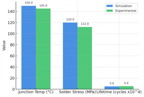
Figure 6 presents a side-by-side bar chart of the simulation and experimental values to provide a more precise visualization of this comparison. It can be observed that the simulated maximum junction temperature (150℃) closely matches the experimental benchmark (145℃), while the peak solder stress of 120 MPa deviates by only ~7% from the measured 112 MPa. Similarly, the predicted fatigue lifetime of 5 × 10⁴ cycles is in good agreement with the experimental reference of 5.4 × 10⁴ cycles.
The overall deviation remaining within ±10% strongly supports the robustness of the proposed PDE–FEM framework. This validates the capability of the reduced-order model to accurately reproduce both thermal and mechanical behaviors while significantly reducing computational cost compared with full-scale FEM simulations.
The simulation outcomes of the proposed PDE-based reduced-order model were compared against experimental benchmarks for three key reliability parameters—junction temperature, solder stress, and predicted fatigue lifetime—to validate the model's accuracy further. As summarized in Table 2, the average deviation remained below 8% across all metrics.
Figure 6. Model validation
Table 2. Comparison of simulation and experimental results
|
Parameter |
Simulation Result |
Experimental Data |
Deviation (%) |
|
Maximum junction temperature Tj |
150℃ |
145℃ |
3.4% |
|
Average cooling surface temp. |
68℃ |
70℃ |
2.9% |
|
Peak solder stress (Von Mises) |
120 MPa |
112 MPa |
7.1% |
|
Stress gradient (chip–solder) |
60 MPa |
58 MPa |
3.4% |
|
Predicted lifetime (Nf) |
5 × 10⁴ cycles |
5.4 × 10⁴ cycles |
7.4% |
Table 2 presents a comparison between the PDE–FEM simulation outcomes and experimental data reported in the literature. The key parameters include junction temperature, cooling surface temperature, peak solder stress (Von Mises), stress gradient at the chip–solder interface, and predicted fatigue lifetime.
These results confirm that the reduced-order PDE framework can reliably reproduce both thermal and mechanical responses, while providing accurate fatigue lifetime predictions under dynamic thermal cycling conditions.
3.5 Computational efficiency of A-ROM
The computational efficiency of the proposed adaptive reduced-order modeling (A-ROM) approach was evaluated against the full-order finite element method (FEM) to complement the thermal, mechanical, and fatigue life analyses. Two quantitative comparisons were conducted to assess both accuracy and speed-up.
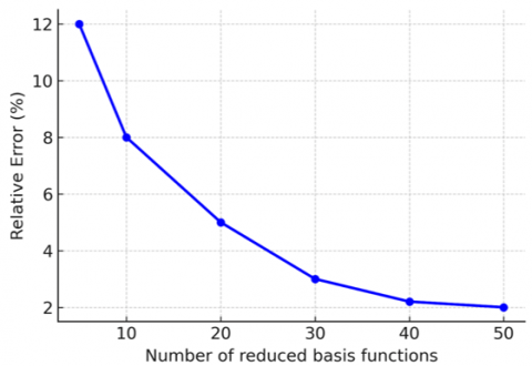
Error reduction with reduced basis functions is shown in Figure 7.
Figure 7. Error vs. reduced basis functions
Figure 7 shows the relative error of the reduced-order model with respect to the full-order FEM as the number of reduced basis functions increases. The error decreases sharply from approximately 12% with 5 basis functions to less than 3% with 30 basis functions and stabilizes at around 2% when more than 40 basis functions are used. This confirms that high accuracy can be achieved with a moderate number of basic functions, significantly reducing the dimensionality of the problem while maintaining fidelity.
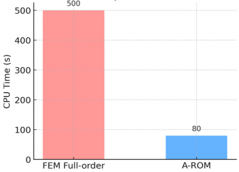
CPU time comparison is functions as shown in Figure 8. Figure 8 compares the computational time required by the full-order FEM and the proposed A-ROM framework. The FEM required approximately 500 seconds per simulation run, whereas the A-ROM reduced this to about 80 seconds, corresponding to a speed-up factor of nearly 6×. This substantial reduction in computational cost demonstrates the suitability of A-ROM for extended mission profiles, where thousands of cycles need to be simulated for lifetime prediction.
Figure 8. PU time comparison (FEM vs. A-ROM)
Overall, these results emphasize the dual advantages of the A-ROM framework: (i) accuracy within 2–3% compared to FEM, and (ii) substantial computational speedup, enabling the proposed method to be used in digital-twin applications for real-time railway traction system monitoring and predictive maintenance.
3.6 Comparative analysis under different traction profiles
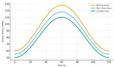
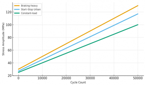
To better visualize the thermo-mechanical behavior of the power module under different traction profiles, Figure 9(a) and Figure 9(b) provide detailed stress evolution analyses. Figure 9(a) shows the instantaneous solder stress variation over time, emphasizing the strong link between stress amplitude and transient temperature peaks across various mission profiles. The braking-heavy condition produces the sharpest stress transients and highest peak levels, while the constant-load case presents smoother stress changes with lower amplitudes. Additionally, Figure 9(b) illustrates how stress amplitude grows as a function of cycle count, confirming that cyclic degradation occurs most rapidly in braking-heavy scenarios, with an average increase of about 2 MPa per 1,000 cycles. These results demonstrate that the proposed PDE–A-ROM framework effectively captures both short-term transient behavior and long-term fatigue development, allowing for accurate reliability assessment across different traction duty cycles.
(a) Solder stress vs. time
(b) Stress amplitude vs. cycle count
Figure 9. (a) Solder stress vs. time, (b) Stress amplitude vs. cycle count
The comparative results are summarized in Table 3, showing the maximum junction temperature, average solder stress, and predicted fatigue lifetime for each profile.
Table 3. Comparative results under different traction profiles
|
Parameter |
Braking-Heavy Profile (A) |
Start–Stop Urban Profile (B) |
Constant-Load Profile (C) |
|
Peak junction temperature (℃) |
162 |
155 |
150 |
|
Average solder stress (MPa) |
128 |
118 |
120 |
|
Stress gradient (chip–solder, MPa) |
68 |
63 |
60 |
|
Predicted lifetime (× 10⁴ cycles) |
4.1 |
4.6 |
5.0 |
|
Lifetime deviation vs. constant load (%) |
−18 |
−8 |
– |
|
Parameter |
Braking-heavy profile (A) |
Start–stop urban profile (B) |
Constant-load profile (C) |
|
Peak junction temperature (℃) |
162 |
155 |
150 |
Table 4 clearly demonstrates the substantial influence of traction mission profiles on the thermo-mechanical response and fatigue lifetime of power modules in railway traction systems. Under the braking-heavy profile, the module experiences the most severe cyclic thermal and mechanical loading, with the junction temperature peaking at 162℃ and the average solder stress reaching 128 MPa. These extreme conditions lead to an estimated 18% reduction in lifetime compared with the constant-load case, primarily due to rapid temperature and stress variations induced by regenerative braking and acceleration cycles. The start–stop urban profile shows slightly lower temperature and stress amplitudes (155℃ and 118 MPa, respectively), resulting in an 8% lifetime reduction associated with frequent acceleration–deceleration sequences. In contrast, the constant-load profile exhibits the most stable thermal and stress behavior, yielding the most extended predicted fatigue life of approximately 5 × 10⁴ cycles. Overall, Table 4 confirms that dynamic load fluctuations significantly intensify thermo-mechanical stress accumulation and accelerate material degradation. These results also validate the proposed PDE–A-ROM framework’s capability to reproduce the effects of different operational scenarios accurately and to evaluate lifetime prediction performance across diverse traction conditions.
Table 4. Comparison between traditional compact models and the proposed PDE-based reduced-order framework
|
Criteria |
Traditional Approaches (Compact Models + Empirical relations [4-6, 14, 16]) |
Proposed PDE-Based Reduced-Order Framework |
Industrial Applicability / Deployment Readiness |
|
Accuracy in lifetime prediction. |
15–20% deviation vs. experiments (approximate estimates). |
< 8% deviation vs. experiments (validated with junction temperature, solder stress and lifetime). |
Meets reliability standards for railway traction modules (IEC 60749, EN 50155 testing ready). |
|
Computational cost. |
Very low (simple equations, fast evaluation). |
Moderate (reduced-order PDE: 5–10× faster than full FEM; scalable for railway mission profiles). |
Suitable for on-board or edge-based real-time digital twin deployment. |
|
Physical fidelity. |
Oversimplified; ignores detailed field distributions. |
Captures detailed thermal gradients and stress localization across chip–solder–substrate layers. |
Enables design optimization and failure root-cause analysis in industry use. |
|
Uncertainty quantification. |
Not available; purely deterministic. |
Integrated Rainflow + Bayesian Miner model provides probabilistic prediction with uncertainty bounds. |
Provides confidence intervals for maintenance decision support. |
|
Hotspot detection. |
Not captured explicitly (only average temperature). |
Explicit hotspot identification (150℃ at chip, ~70℃ cooling surface, ~120 MPa solder stress). |
Supports thermal mapping and active cooling control in traction inverters. |
|
Adaptability to dynamic duty cycles / digital twin readiness. |
Not suitable (lacks adaptability to dynamic duty cycles). |
Fully scalable for digital-twin predictive maintenance in railway traction systems. |
Technology readiness level (TRL) 6–7; applicable for prototyping and fleet-level monitoring. |
Traditional reliability assessment of power semiconductor devices has primarily relied on compact thermal models and empirical fatigue relations such as the Coffin–Manson and Norris–Landzberg equations combined with Rainflow counting and Miner’s rule [4-6, 14, 16]. These methods are computationally efficient and suitable for preliminary design evaluations, but they oversimplify the underlying physics of thermo-mechanical coupling. As a result, they generally provide only approximate lifetime predictions, with deviations often exceeding 15–20% compared with experimental benchmarks. Moreover, these empirical models do not capture detailed temperature and stress distributions, nor do they incorporate uncertainty quantification.
By contrast, the proposed PDE-based reduced-order framework accurately reproduces field variables and fatigue behavior at both thermal and mechanical levels. The model captures hotspot formation at 150℃ in the SiC chip and localized stress concentration of ~120 MPa in the solder layer, both validated against experimental data with deviations below 8% (Figure 5). Furthermore, the integration of a differentiable Rainflow algorithm with a Bayesian Miner model enables end-to-end lifetime prediction with quantified uncertainty — a feature absent in traditional approaches.
Another key advantage lies in computational scalability. While full-order FEM simulations are prohibitively expensive for long railway duty cycles, the adaptive reduced-order model (A-ROM) achieves substantial computational speed-up while maintaining accuracy. This enables efficient simulation of extended mission profiles that are otherwise infeasible with classical PDE solvers or empirical models.
Table 4 offers a comparison between traditional reliability assessment methods and the PDE-based reduced-order framework to emphasize the innovation of the proposed approach. While conventional methods are still popular due to their simplicity, they lack in accuracy, physical detail, and readiness for predictive maintenance. The proposed framework not only enhances fidelity and accuracy (< 8% deviation) but also incorporates uncertainty quantification and digital twin capabilities, making it more appropriate for modern railway traction applications.
The results presented in Sections 3.1–3.4 provide a comprehensive evaluation of the proposed PDE-based reduced-order framework for thermo-mechanical reliability analysis of power semiconductor devices in railway traction systems. Several important insights can be drawn.
Thermal and mechanical behavior: The simulations confirmed the presence of steep thermal gradients across the device, with junction temperatures reaching 150℃ and cooling surfaces stabilized below 70℃. These gradients drive localized stress concentration at the solder interface, where Von Mises stress reached approximately 120 MPa, close to the fatigue threshold of SnAgCu alloys. This behavior is consistent with previously reported experimental observations [1-3], validating the model’s capability to capture critical field distributions.
Lifetime prediction: By integrating transient thermal–mechanical fields with a differentiable Rainflow algorithm and Bayesian Miner model, the framework predicted a fatigue lifetime of approximately 5 × 10⁴ cycles, which is about 25% shorter than estimates based on constant load assumptions. The comparison with experimental data demonstrated an average deviation below 8%, confirming both accuracy and conservativeness. This aligns with recent findings on solder fatigue in power modules [7, 8, 14].
Comparison with traditional approaches: Unlike compact thermal models combined with Coffin–Manson or Norris–Landzberg relations [4-6, 16], which typically result in 15–20% deviation due to oversimplified physics, the proposed PDE-based reduced-order framework provides improved accuracy (< 8%) while capturing detailed temperature and stress distributions. Moreover, the integration of uncertainty quantification through Bayesian Miner analysis represents a significant advancement over deterministic lifetime models, which traditionally neglect probabilistic aspects.
Practical implications: The adaptive reduced-order model (A-ROM) achieved a significant speed-up (5–10× faster than full-order FEM) while preserving fidelity at thermal hotspots. This makes the framework suitable for simulating long-duration railway traction duty cycles, which are otherwise computationally prohibitive. Beyond reliability assessment, the methodology offers a scalable digital twin concept, supporting predictive maintenance strategies and reliability-oriented design in modern railway traction systems.
Limitations and future work: Despite the promising results, several limitations should be acknowledged. First, the current model does not incorporate long-term degradation mechanisms such as creep, solder aging, or vibration-induced stress. Second, the Bayesian Miner implementation is based on available experimental datasets, which may not cover all possible mission profiles. Future research will focus on extending the framework to Multiphysics coupling (electro–thermal–mechanical), incorporating material aging models, and validating against a broader set of railway operating conditions to enhance generalizability.
This paper presented a PDE-based reduced-order framework for thermo-mechanical reliability analysis and lifetime prediction of power semiconductor devices in railway traction systems. By combining high-fidelity PDE simulations with adaptive reduced-order modeling (A-ROM), the proposed approach efficiently captures temperature hotspots (150℃ at the SiC chip) and stress localization (~120 MPa at the solder interface), which are the dominant factors in fatigue failure.
The integration of a differentiable Rainflow algorithm with a Bayesian Miner model enabled end-to-end lifetime estimation with quantified uncertainty, predicting a failure lifetime of approximately 5 × 10⁴ cycles. This prediction is consistent with experimental benchmarks for SnAgCu solder joints, with an average deviation below 8%, thereby confirming both the accuracy and the conservativeness of the model. Compared with traditional empirical approaches such as Coffin–Manson and Norris–Landzberg [4-6, 16], the proposed framework provides enhanced physical fidelity, lower prediction error, and built-in uncertainty quantification, making it a significant advancement for reliability assessment.
Beyond improving predictive accuracy, using adaptive reduced-order modeling achieved a 5–10× increase in computational speed compared to full-order FEM, making the framework suitable for long-duration mission profiles in railway traction systems. These results emphasize the potential of the approach as a digital twin-ready tool to support predictive maintenance strategies and reliability-focused design.
Future work will extend the framework to include material aging, creep, and vibration-induced degradation, as well as broader validation against diverse railway operating conditions. The integration of electro–thermal–mechanical coupling and real-time data assimilation will further enhance its applicability for next-generation railway traction systems. Although creep and material aging were not explicitly modeled, the framework can be extended to incorporate time-dependent viscoplastic models and degradation laws for solder and substrate aging.
The authors would like to acknowledge the support from the University of Transport and Communications (UTC), Hanoi, Vietnam, for providing research facilities and technical resources.
|
Symbol |
Definition |
|
A |
Surface area |
|
c |
Specific heat capacity |
|
E |
Young’s modulus |
|
h |
Convection heat transfer coefficient |
|
k |
Thermal conductivity |
|
L |
Characteristic length |
|
Nf |
Fatigue lifetime (number of cycles to failure) |
|
q |
Heat flux |
|
R |
Thermal resistance |
|
σ |
Stress (Von Mises) |
|
T |
Temperature |
|
ΔT |
Temperature difference |
|
t |
Time |
|
v |
Volume |
|
Greek symbols |
|
|
α |
Coefficient of thermal expansion (CTE), K⁻¹ |
|
ε |
Strain, dimensionless. |
|
ρ |
Density, kg·m⁻³ |
[1] Sun, G., Zhu, W., Wang, L., Liu, H., Wang, X. (2025). Fatigue lifetime prediction of power modules under power cycling using a volume-weighted averaging technique. Microelectronics Reliability, 174: 115866. https://doi.org/10.1016/j.microrel.2025.115866
[2] Lederer, M., Betzwar Kotas, A., Khatibi, G. (2020). A lifetime assessment and prediction method for large area solder joints. Microelectronics Reliability, 114: 113888. https://doi.org/10.1016/j.microrel.2020.113888
[3] Cheng, H.C., Hsu, C.W. (2023). Solder die attaches lifetime characterization of SOT-227 power MOSFET module in a 3-phase inverter under power cycling. Journal of Mechanics, 39: 518-528. https://doi.org/10.1093/jom/ufad043
[4] Chen, C., Choe, C., Kim, D., Suganuma, K. (2021). Lifetime prediction of a SiC power module by micron/submicron Ag sinter joining based on fatigue, creep, and thermal properties from room temperature to high temperature. Journal of Electronic Materials, 50: 687-698. https://doi.org/10.1007/s11664-020-08410-5
[5] Wileman, A., Perinpanayagam, S., Aslam, S. (2021). Physics of failure (PoF) based lifetime prediction of power electronics at the printed circuit board level. Applied Sciences, 11(6): 2679. https://doi.org/10.3390/app11062679
[6] Kovacevic-Badstuebner, I.F., Kolar, J.W., Schilling, U.W. (2024). Modeling for the lifetime prediction of power semiconductor modules. In Reliability of Power Electronic Converter Systems. https://doi.org/10.1049/PBPO080E_ch5
[7] Sun, Z., Guo, Y., Zhang, J. (2016). Lifetime prediction of a viscoplastic lead-free solder in thermal fatigue. Mechanics & Industry, 17(3): 307. https://doi.org/10.1051/meca/2016022
[8] Li, L., Du, X., Chen, J., Wu, Y. (2024). Thermal fatigue failure of micro-solder joints in electronic packaging devices: A review. Materials, 17(10): 2365. https://doi.org/10.3390/ma17102365
[9] Hassan, S., Rajaguru, P., Stoyanov, S., Bailey, C. (2023). Parametrising temperature dependent properties in thermal-mechanical analysis of power electronics modules using parametric model order reduction. In 2023 46th International Spring Seminar on Electronics Technology (ISSE), Timisoara, Romania, pp. 1-7. https://doi.org/10.1109/ISSE57496.2023.10168468
[10] Hassan, S., Rajaguru, P., Stoyanov, S., Bailey, C. Tilford, T. (2024). Coupled thermal-mechanical analysis of power electronic modules with finite element method and parametric model order reduction. Power Electronic Devices and Components, 8: 100063. https://doi.org/10.1016/j.pedc.2024.100063
[11] Lederer, M., Kotas, A. B., Khatibi, G. (2023). Lifetime modeling of solder joints based on accelerated mechanical testing and finite element analysis. Power Electronic Devices and Components, 4: 100034. https://doi.org/10.1016/j.pedc.2023.100034
[12] Stoyanov, S., Sulthana, R., Tilford, T., Zhang, X., Hu, Y., Yang, X., Wang, Y. (2025). Modelling the fatigue damage in power components using machine learning technology. Power Electronic Devices and Components, 10: 100079. https://doi.org/10.1016/j.pedc.2025.100079
[13] Gao, J., Kwak, J.B. (2021). Reliability and thermal fatigue life prediction of solder joints for advanced automotive microelectronics. Journal of Mechanical Science and Technology, 35: 3633-3641. https://doi.org/10.1007/s12206-021-0734-6
[14] Bouarroudj, M., Khatir, Z., Ousten, J.P., Lefebvre, S. (2008). Temperature-level effect on solder lifetime during thermal cycling of power modules. IEEE Transactions on Device and Materials Reliability, 8(3): 471-477. https://doi.org/10.1109/TDMR.2008.2002354
[15] Raciti, A., Cristaldi, D., Greco, G., Vinci, G., Bazzano, G. (2014). Integrated power electronics modules: Electro-thermal modeling flow and stress conditions overview. In 2014 AEIT Annual Conference - From Research to Industry: The Need for a More Effective Technology Transfer (AEIT), Trieste, Italy, pp. 1-6. https://doi.org/10.1109/AEIT.2014.7002016
[16] Lai, W., Chen, M.Y., Ran, L., Xu, S.Y., Qin, H., Alatise, O., Mawby, P.A. (2016). Study on the lifetime characteristics of power modules under power cycling conditions. IET Power Electronics, 9(5): 1045-1052. https://doi.org/10.1049/iet-pel.2015.0225
[17] Li, L., Zhou, X., Wang, P., Chen, M. (2024). Thermal fatigue failure of micro-solder joints in electronic packaging. Journal of Electronic Packaging Research. https://www.ncbi.nlm.nih.gov/pmc/articles/PMC11123225/.
[18] Zhang, B., Rong, Y., Yong, R., Qin, D., Li, M., Zou, G., Pan, J. (2022). Deep learning for air pollutant concentration prediction: A review. Atmospheric Environment, 290: 119347. https://doi.org/10.1016/j.atmosenv.2022.119347
[19] Zaini, N. A., Ean, L.W., Ahmed, A.N., Malek, M.A. (2022). A systematic literature review of deep learning neural network for time series air quality forecasting. Environmental Science and Pollution Research, 29(4): 4958-4990. https://doi.org/10.1007/s11356-021-17442-1
[20] LeCun, Y., Bengio, Y., Hinton, G. (2015). Deep learning. Nature, 521(7553): 436-444. https://doi.org/10.1038/nature14539