Nacira Tkouti*![]() | Hani Benguesmia
| Hani Benguesmia![]() | Raihane Mechgoug
| Raihane Mechgoug![]() | Naima Rahoua
| Naima Rahoua![]()
© 2025 The authors. This article is published by IIETA and is licensed under the CC BY 4.0 license (http://creativecommons.org/licenses/by/4.0/).
OPEN ACCESS
In this investigation, a comparative investigation of three-level and seven-level Neutral-Point Clamped (NPC) inverters in grid-connected photovoltaic (PV) systems was carried out to investigate the minimization of total harmonic distortion (THD) and power-quality. Higher PLC inverter levels generally offer better operational performance; however, they have more complexity and cost associated, but need to be justified. Using Matlab/Simulink simulations, with Phase Disposition Sinusoidal Pulse Width Modulation (PD-SPWM) for switching signal generation, the seven-level NPC inverter reached a THD level of 3.50%, which is in accordance with IEEE Standard 519-2014 (≤5% limit) while the three-level inverter reached a THD performance of 8.54%, which is unacceptable. The seven-level inverter was able to maintain grid-compatible voltage, even when solar irradiance changed, by utilizing three (PI) controllers to regulate the DC voltage (Vdc), direct current (Id) and quadrature current (Iq). The results of this investigation show that the seven-level inverter improved harmonic suppression and dynamic responses, and it is an option to consider for grid-connected PV systems. However, the cost and complexity of this inverter's components and controls need to be considered when balanced against operational performance improvements. This study exposes useful information for selecting optimum inverter topologies to balance efficiency, cost, and quality of power when integrating renewable energy.
photovoltaic, multilevel inverter, NPC, PI controller, grid, THD
The demand for renewable energy has increased significantly over the years due to fossil fuel scarcity and the impact of fossil fuels [1].
However, due to its small size, easy installation and use, solar power (PV) is popular among both residential and industrial users [2-4].
The connection of this solar power source to an electrical distribution network is not simple. Although this PV energy is presented as the future energy, it has the disadvantage of being intermittent (very dependent on irradiance and temperature). This feature has a negative impact on the electrical network [3].
Furthermore, a significant portion of the cost of a photovoltaic system lies in the filtration components (L, C) that ensure energy quality and heavy, expensive system.
An inverter is an essential part of any sustainable energy system to convert electricity from DC current to AC current.
A new development in power electronics is that multilevel inverters by the use of which the power conversion is performed with high current quality and low total harmonic distortion (THD) [5]. There are three topologies of multilevel inverters, which are: 1) diode clamped, 2) capacitor clamped, and 3) cascaded H-bridge inverter [6]. The quality of electricity produced by multi-level solar panels in photovoltaic systems connected to the network is a critical factor to consider as it has a significant influence on the system's efficiency.
In this context, Boucheriette et al. [7] propose a grid-connected PV system using a five-level NPC inverter to reduce harmonic distortion and provide better capacity. Voltage from a PV system has fluctuations corresponding to solar radiation, thus, a PI regulator is proposed to stabilize voltage, and therefore, a correct PI can be determined by using a Genetic Algorithm (GA). Simulations are conducted in Matlab/Simulink and show that the PI controller tuned with a GA provides better stability, remarkable accuracy, and reduces grid current THD while changing solar radiation conditions than a normal PI controller.
Najafi and Yatim [8] offer an improved multilevel inverter topology that uses a reversing-voltage device to overcome common drawbacks, including a high number of components, complex controls, and challenges in voltage balancing. In comparison to the conventional designs and methods, this inverter topology reduces the number of components, carrier signals, and gate drives which then reduces overall cost and complexity, especially at higher voltage levels. Experimental results for the new seven-level prototype validate their enhanced performance, while still maintaining the unwanted features like low harmonic distortion and high efficiency while eliminating the traditional drawbacks.
Janardhan et al. [9] describe a new transformer less inverter topology for grid-connected PV systems with full consideration of common-mode voltage (CMV) and leakage current analysis. The research compares the leakage current performance of the new topology with existing transformer less topologies using simulation work. It also investigates various full-bridge inverter topologies with the implementation of different PWM techniques to understand the impact on CMV and leakage currents. The proposed topology shows a reduction in leakage and improvement in efficiency, making it a potential solution for PV applications.
Mechgoug et al. [10] present a fuzzy fractional-order PI (FFOPI) control strategy for a grid-connected PV system using a five-level NPC inverter, which minimizes harmonic distortion and maximizes power capacity. Since PV output voltage fluctuates with solar radiation, three FFOPI controllers regulate the inverter’s DC voltage (Vdc) and grid currents (Id, Iq) to keep the grid connection stable. The performance of the FFOPI is superior in dynamic response and precision of PV-grid integration compared to that of a standard fuzzy PI (FPI) controller because fractional-order calculus is employed.
Boucheriette et al. [11] provide a grid-connected PV system based on multi-level inverter (MLI) controlled by FFOPI regulators to improve efficiency and power quality. The three FOPI control loops - two for the grid currents, Id, Iq and the DC-link voltage, Vdc - were optimized using meta-heuristic algorithms (PSO, ABC, GWO) to minimize total harmonic distortion (THD).
Simulations conducted in Matlab/Simulink show that the GWO-tuned FOPI is more accurate than the PSO and ABC-tuned FOPI control loops and that the GWO-tuned FOPI can improve inverter performance by improving THD. Majumder et al. [12] introduce a proportional-resonant (PR) controller for synchronizing a five-level cascaded H-bridge multilevel inverter (CHBMI) with the grid in a solar PV system. Unlike traditional PI controllers, the PR controller eliminates steady-state errors and coupled feedback terms, while also compensating for selective grid current harmonics. The proposed method demonstrates superior performance in grid synchronization and harmonic mitigation, offering a more effective solution for PV-grid integration.
Recent literature on PV-grid systems has shown progressive research in the application and design of multilevel inverter (MLI) control, stability, and performance, with rapid advancements in MLI control strategy development demonstrating a distinct path towards improved controller performance, and stability. Current literature consistently highlights the weaknesses of conventional control methods associated with sudden fluctuations in solar irradiance or grid faults, leading the way for more advanced control strategies like Proportional-resonant (PR) controllers providing a higher response in performance while minimizing zero steady state error and increasing harmonic compensating performance [13]. Further advances to these novel approaches have been proposed like FOPI and Fuzzy FOPI (FFOPI) controllers that have been shown to improve dynamic response time and decreased total harmonic distortion (THD) relative to conventional PI controllers [14]. Performance of these advanced control strategies has been further optimized through models using meta-heuristic algorithms such as PSO, ABC, and GWO [14, 15].
The PI controller is the most widely used classic controller due to its simple structure and is easy to use [3].
The control system consists of three control circuits based on the PI controller: PI1 is used to control the voltage of the intermediate circuit (Vdc) and PI 2, PI 3 are used for controlling the direct and quadratic currents (Id, Iq) generated by a three- or seven-level inverter.
The proposed controllers are aimed at improving the performance of multi-level inverters, by reducing total harmonic distortion (THD) in both the output current and voltage. For this reason, a comparison study will be carried out to implement a three-level inverter, and a seven-level inverter that will be discussed in the following sections.
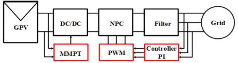
As shown in Figure 1 [7], the proposed system consists of four main parts: the delayed charges from the PV array, buck converters (DC/DC), an NPC inverter (inverter configuration), and an LC filter. The filter includes filtering inductance, and capacitors (Lf, Cf) to smooth the current delivered to the system.
Figure 1. Bloc diagram of grid connected photovoltaic system
In this study, we will do a simulation with Matlab/Simulink of all equipment of the PV power system connected to the network. We will also introduce a management system, which aims to control the energy and the power produced by photovoltaic panels.
The simulation results are presented as well as spectral analysis for the two multi-level 3 and 7 inverters.
The objective of this work is to do a comparative study between the two multi-level 3 and 7 NPC inverters in terms of distortion factor THD and active power.
The rest of the paper is organized as follows: Section 2 goes through the solar grid system modeling, which includes the PV array, the DC-DC converter and the LC filter design. Section 3 covers the analysis of the control system and the PI regulation strategy. Section 4 covers the modulation technique. In Section 5 the controller design and performance are assessed. In Section 6, we present simulation results and assess the comparison. Finally, Section 7 concludes the paper with recommendations for future work.
2.1 Photovoltaic cell
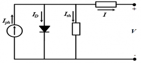
A PV array is composed of series and parallel configurations of PV cells. The five-parameter single-diode model (Rs, Rsh, Iph, I0, A) is illustrated in Figure 2, while the full specifications of the PV system are provided in Table 1.
Figure 2. Equivalent model of a real photovoltaic cell
Table 1. PV specification
|
Maximum Power Pmax |
Open Circuit Voltage |
Short Circuit Current |
Current at Pmax |
Voltage at Pmax |
Cell Series Number |
|
214.54 W |
36 V |
8.01 A |
7.41 A |
29 V |
60 |
$I_{p h}-I_0\left(e^{\frac{q}{n A K T}\left(V+R_s \times 1\right)}-1\right)-\frac{V+R_s \times 1}{R_{s h}}$ (1)
I: The current delivered by the photovoltaic module.
Rsh: Shunt resistance.
Iph: Photoelectrical current.
I0: Saturation current.
Rs: Series resistance.
K: Boltzmann factor 1.38 × e-23 JK.
n: Coefficient the diode ideality.
The photoelectric current (Iph) depends on irradiation and temperature as shown in Eq (2).
$I_{p h}=\left(I_{p h, n}+K_I \Delta T\right) \times \frac{G}{G_n}$ (2)
$I_0=\frac{\left(I_{s c n}+K_I \Delta T\right)}{\exp ^{\left(\frac{V_{o c n}+K_v \Delta T}{A V_{t h}}\right)-1}}$ (3)
$\Delta T=T-T_n$ (4)
Iscn: short-circuit current under nominal conditions (Gn = 1000 W/m2, Tn = 25℃) is represented.
T and Tn: Respectively, the cell's ambient and nominal temperatures.
G and Gn: The current and nominal irradiation respectively.
KI: The short circuit current's temperature coefficient while the open circuit voltage's is Kv.
Vth: The thermal junction constant Vth = KT/q, where q is the electron burden (1.602 × 10⁻¹⁹ C).
2.2 DC-DC converter
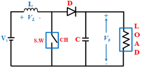
The DC-DC Converter used in this study is the elevator (boost) the output voltage is higher than the input voltage.
The model of the DC/DC converter is shown in Figure 3 and its parameters are shown is Table 2.
Figure 3. Boost converter circuit [11]
Table 2. The boost converter parameters
|
Parameter |
C1 (F) |
C2 (F) |
L (H) |
f (KHz) |
|
Value |
1000e-6 |
1.500e-6 |
0.0022 |
10 |
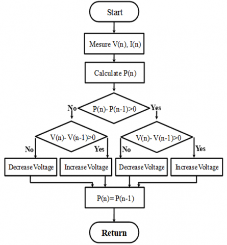
The Perturb and Observe (P&O) MPPT method was used in this work as shown in Figure 4. The P&O method is not only widely used because of its simplicity but also with its ability to be used in real-time. The method operates by perturbing a (changing) the voltage of the solar panel, measuring the power output, and iterations of perturbation-observing continue until the maximum power point (MPP) is found.
Figure 4. Flowchart of P&O MPPT
2.3 LC filter
To improve the quality of energy injected into the grid, a low filter is needed to eliminate the cutting harmonics. To calculate the filter parameters, the methodology is adopted where the resonance frequency of the filter is set at the tenth of that of the cutting. So, we have:
$1=L C \omega^2$ (5)
$\omega^2=2 \pi f_c^2$ (6)
$f_c=\frac{f_d}{10}$ (7)
fc: Resonance frequency.
fd: Cut off frequency.
All parameters of the filter settings are provided in Table 3.
Table 3. Filter parameters
|
Parameters |
Rf |
Lf |
Cf |
|
System with inverter Three-level |
1e-3 Ω |
0.01 H |
1.1749 e-6 F |
|
System with inverter Seven-level |
1e-3 Ω |
0.005 H |
1.1438 e-6 F |
The LC filter values listed in Table 3 were chosen in consideration of the unique harmonic characteristics of the three-level and seven-level inverters. The larger values of inductor (Lf = 0.01 H) were needed for the three-level inverter, which has a high THD and must filter out switching-frequency harmonics.
The seven-level inverter has a small inductor (Lf = 0.005 H) and fine enough voltage steps so that THD performance will not be compromised, allowing also using the small value of inductor. Capacitor values were determined to match the resonance frequency (fc) with the harmonic spectrum of the inverter system. A single filter can be designed for both architectures, but would either over-compensate (higher cost) or idealize (THD violations), making generic filtering impossible. Topology optimization is required for each inverter architecture and depending on the THD, will help define logical and reasonable filter designs.
2.4 Topology of the diode clamped multilevel
The basic concept of this inverter is to use the diodes to accomplish multiple voltages across the separate phases of a series of electrical devices [16]. Diodes, while transmitting a limited voltage, lessen the electrical component's loads. Nonetheless, the maximum voltage you can get is only half the input DC voltage in a diode-clamp structure and this is the main drawback of the clamped converter structure. There are ways to lessen this disadvantage, for instance, by adding additional switches, diodes and capacitors. However, typically, the capacitor balancing means these inverters are limited to become three levels as they operate at fundamental frequency, therefore high efficiency is achieved as a back-to-back power transmission system technology [17].
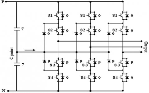
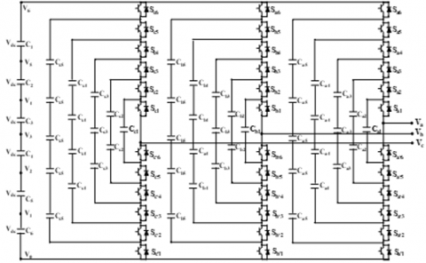
An n-level inverter leg corresponds to 2(n–1) switching devices and (n–1)(n–2) clamping diodes. For instance:
•A three-level inverter (n = 3) consists of four switching devices and two clamping diodes per leg, as stated in Figure 5(a).
•A seven-level inverter (n = 7) consists of twelve switching devices and thirty clamping diodes per leg, as stated in Figure 5(b).
As more steps are created for voltage levels, the output voltage waveform is sinusoidal and the quality is improved [3].
The DC output voltages Vdc of the three-level and seven-level NPC inverters under changing irradiance conditions are presented in Figure 6(a) and Figure 6(b), respectively.
In the case of a generalized three-phase diode-clamped Multilevel Inverter (MLI), the DC-link is shared and the required (n-1) capacitors are all used to produce voltage levels. This is a basic aspect of the design of the topology such that these capacitors generate the neutral points referenced by the clamping diodes. This is relevant for the sake of completeness in understanding the component count and total complexity and price of the system.
Component formulas (for m-level, three-phase DC-MLI):
•DC bus capacitors (shared across phases): m−1
•Power switches: per phase 2(m−1); total 6(m−1)
•Clamping diodes: per phase (m−1)(m−2); total 3(m−1)(m−2)
In our case, the component counts are presented in Table 4.
Figure 6. The DC output voltage (Vdc) for the (a) three-level and (b) seven-level NPC inverters under changing irradiance
Table 4. Parameters sizing of power components for three-level and seven-level three-phase CHB inverter
|
Levels (m) |
DC Bus Capacitors (total) |
Switches Per Phase |
Switches (3 Phase Total) |
Diodes Per Phase |
Diodes (3 Phase Total) |
|
3 |
2 |
4 |
12 |
2 |
6 |
|
7 |
6 |
12 |
36 |
30 |
90 |
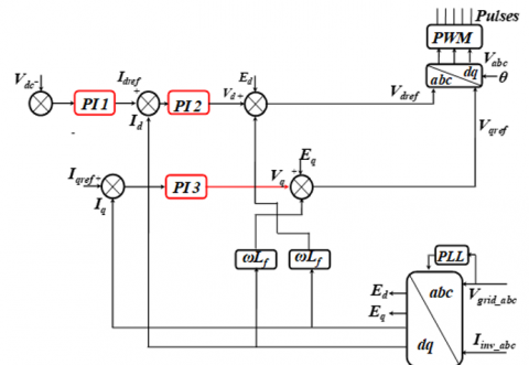
For the intended NPC multilayer inverter, a specific control system has been created in order to facilitate the transfer of electricity from the PV generator to the grid. To achieve this, a controller had to be linked. To utilize a PI controller to guarantee the DC voltage buses' stability in their reference value. The current references and active current controllers for the network created by the PV panels will be defined by the output of this PI controller, as demonstrated in Figure 7.
Figure 7. Bloc diagram of control system
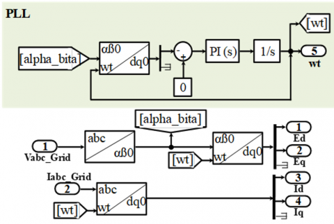
id* and iq* are used to regulate grid current. The D-Q axes theory uses the three-phase currents to produce id and iqcurrents. The ED and EQ outputs of the current controllers can be utilized as reference voltages to produce PWM.
The conversion process from the ED and EQ signals to the three-phase reference voltages (VAref, VBref, and VCref) is illustrated in Figure 8(a) and 8(b). This transformation relies on the grid voltage phase angle, which is provided by the PLL, as discussed earlier.
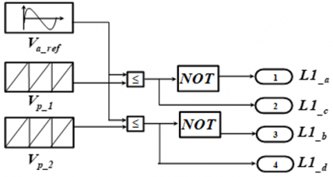
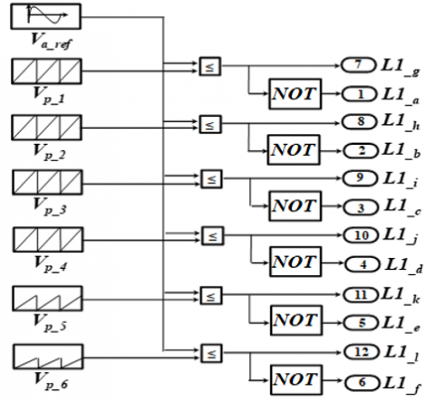
This technique requires (N-1) triangular signals with the same frequency fp and the same amplitude Ap, these triangular signals are compared, for each phase, with a reference signal of amplitude Arefand frequency fref. The expressions provide the modulation rate ma ma and the frequency ratio mf, respectively [18].
$m_a=A_{\mathrm{ref}} /(N-1) A_p$ (8)
$m_f=f_p / f_{r e f}$ (9)
5.1 Classical PI
The initial values of the controller parameters KP, Ki are presented in Table 5.
Table 5. PI parameters
|
Parameters |
PI Three-Level Inverter |
PI Seven-Level Inverter |
||
|
Kp |
Ki |
Kp |
Ki |
|
|
Voltage |
0.2 |
2 |
0.15 |
5 |
|
Current d |
10 |
200 |
10 |
300 |
|
Current q |
10 |
200 |
10 |
300 |
The PI controller parameters found in Table 4 were determined using the Ziegler-Nichols method as follows: In practice, the Ziegler-Nichols tuning method was used as follows:
Step 1 Set Ki=0 and then increase Kpuntil the system sustained oscillations (critical gain Kcr).
Step 2 Measure the period of the oscillation Tcr.
Step 3 Use the Ziegler-Nichols rules to determine Kp and Ki (e.g., Kp = 0.6 Kcr, Ki = 2Kp/Tcr for PI controller).
The tuned parameters were verified in Matlab/Simulink simulations under varying irradiance conditions (400–1000 W/m²) to verify robustness. The values determined resulted in dynamic response (settling time) being balanced with stability (overshoot in Vdc, Id, and Iq).
The Ki values of the seven-level inverter (e.g., 300 vs. 200 for Id) reflect the increased complexity of the inputs and the faster integral action needed to compensate for harmonic distortions. The lower Kp for Vdc (0.15 vs. 0.2) represented the 7-L inverter having smoother transitions in voltages and therefore reduced dependency on proportional gain [19-21].
5.2 Network synchronization
In photovoltaic systems connected to the network, it is necessary to synchronize the injected network current with the network voltage, in accordance with the standards in force in this area. Thus, network synchronization is a crucial task for network monitoring, as it will have a significant impact on the dynamic performance and stability of the overall control system. The PLL model is presented in Figure 9.
Figure 9. PLL Simulink model
A PI regulator is used to adjust (Vdc ref and Vdc bus), (Idc ref, Id and Iqref, Iq).
5.3 Multi-level inverter performance evaluation
We used three performance parameters are Harmonic distortion (THD).
$T H D=\frac{\sqrt{\sum_{i=2}^N H_i^2}}{F_1}$ (10)
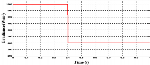
In Figure 10, the applied solar irradiance profile used to test system performance under transient conditions, featuring a step increase from 400 W/m² to 1000 W/m² at t = 0.4 s.
Figure 10. The solar radiation
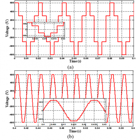
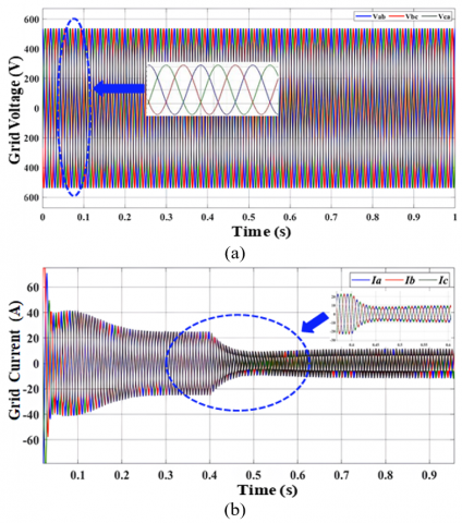
Figure 11 demonstrates proper operation of the three-level inverter system in terms of converting DC to AC, and then injecting current back into the grid. Figure 11(a) displays the voltage output of the inverter after it passes through the LC filter.
Figure 11. Direct and quadratic components of DC voltage and currents for a three-level inverter: (a) grid voltage, (b) grid current
This has the characteristic staircase pattern of a multilevel inverter, alternating between +Vdc/2, 0, and -Vdc/2. While this is a considerable advantage compared to a two-level inverter, it certainly isn't a perfect sine wave and is still significantly distorted through harmonics.
Figure 11(b) shows the resulting current injected into the grid. With the LC filter combined with the PI controller action, the current has a highly sinusoidal waveform and appears dramatically improved over the voltage waveform from the inverter in Figure 11(a).
The improvement in the current provides a clear indication of the successful operation of the control system, which regulates current and improved the distortion caused by harmonics in the voltage.
Figure 11 demonstrates proper operation of the three-level inverter system in terms of converting DC to AC, and then injecting current back into the grid. Figure 11(a) displays the voltage output of the inverter after it passes through the LC filter.
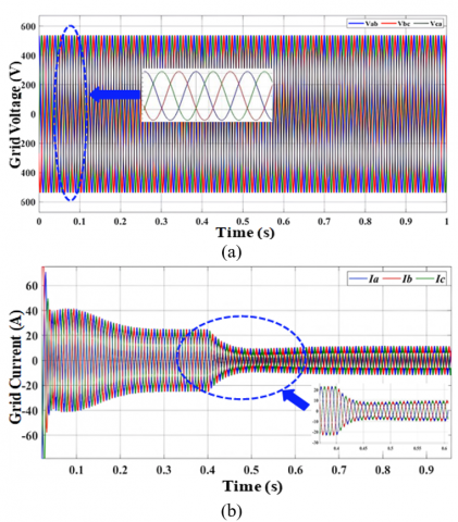
As seen in Figure 12, the seven-level inverter provides a better output voltage waveform and has drastically lower harmonic distortion.
Figure 12. Direct and quadratic components of DC voltage and currents for a seven-level inverter: (a) grid voltage, (b) grid current
Figure 12(a) demonstrates this output voltage waveform. The primary distinction from Figure 11(a) can be observed immediately, specifically, the steps of the staircase waveform are much finer.
By using the seven switching combinations (±3Vdc/2, ±Vdc, ±Vdc/2, 0) output voltages, the inverter can much more closely resemble a pure sine wave, resulting in lower low-order harmonic distortion.
This great output is then observable in the output current waveforms shown in Figure 12(b).
Where this current waveform can be observed to be an extremely smooth, nearly perfect sinusoid.
The excellent performance in this section is attributable to the multilevel topology where the output stage has to perform less filtering to achieve grid-compliant current.
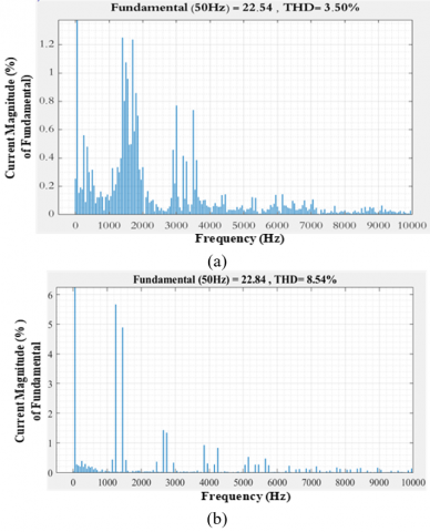
The results of the Fast Fourier Transform (FFT) analysis of the output current of both inverters is illustrated in Figure 13. FFT allows for an analysis of the complex inverter output waveform and resolves it into the frequency components allowing for a calculated measurement of harmonic distortion. The seven-level inverter (Figure 13(a)) has a much cleaner, more sinusoidal output current with considerably less harmonic distortion (THD = 3.50%), when compared to the the output current of the three-level inverter (Figure 13(b)), which displays a considerably higher distortion (THD = 8.54%).
The major benefit of the seven-level inverter is its ability to produce a stepped voltage waveform that much more closely resembles a pure sine waveform. As levels increase, the voltage steps are smaller, therefore decreasing the staircase effect and the subsequent high frequency harmonics produced during switching. The seven-level inverter THD of 3.50% meets international power quality standards (IEEE 519), making it a feasible system for direct grid compliance. The 3-level inverter THD of 8.54% does not meet these standards.
Ultimately, Figure 13 provides the tangible and quantitative evidence that supports the main thesis of this paper. That while it is more complex, a seven-level NPC inverter provides a significant improvement in output quality (THD) when compared to a three-level inverter for the purposes of solar PV grid integration.
Figure 13. Current total harmonic distortion (THD) analysis: (a) seven-level inverter, (b) three-level inverter
The total harmonic distortion of the injected alternating current before and after filtering are all provided in Table 5.
Table 6 shows that seven-levels inverter provides a lower THD of the current after filtering THD% = 3.5 and active power of 1.068e4 when compared to three-level inverter.
Table 6. Comparison of results of the seven-level inverter and three-level inverter
|
|
3 L Inverter |
7 L Inverter |
|
THD % Current before filtering |
12.34% |
5.67% |
|
THD % Current after filtering |
8.54% |
3.50% |
|
Active Power (KW) |
8.23 |
10.68 |
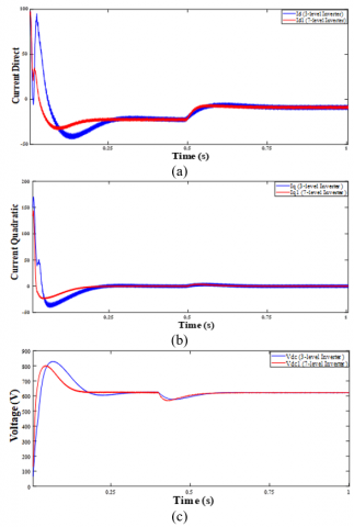
Figure 14 depicts the dynamic operation of the control system for both inverters when solar irradiance suddenly increases (Figure 9).
Figure 14. The direct, quadratic currents and Vdc voltage, for three and seven-level inverter: (a) direct current, (b) quadratic current, (c) voltage
The most important conclusion is that the seven-level inverter exhibits better control and stability. Figures 14(a) present the direct current Id, the Id controls the active power flow. Both inverters are able to track their reference command, but the seven-level inverter shows less overshoot and a more stable and smoother response than the three-level inverter following the change in irradiance. Figure 14(b) present quadrature Current (Iq), the Iq controls the reactive power (which for unity power factor should be zero). The seven -level inverter maintains a much tighter control around zero indicating excellent reactive power management. The three-level inverter has more deviation from and oscillation about zero. Figure 14(c) exhibits DC-Voltage (Vdc). This figure exhibits the stability of the DC voltage from the solar panels. The seven-level inverter maintains a much more stable and constant voltage with very little fluctuation, compared to the three-level inverter, after the disturbance. The three-level inverter shows a much larger dip in voltage and more ripple.
The seven-level inverter's control system, utilizing PI controllers, is more effective as there is reduced overshoot, improved regulation, and enhanced stability of primary parameters (Id, Iq, and Vdc, step changes in sunlight).
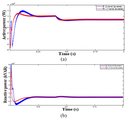
Figure 15 compares the active (P) and reactive (Q) power response of the three-level and seven-level inverters to step changes in solar irradiation. For active power (Figure 15(a)), the seven-level inverter responds quickly and stably with little disturbance, while the three-level inverter shows oscillatory response with overshoot and lengthy settling time, indicating poor control. In terms of reactive power (Figure 15(b)), the seven-level inverter is around zero, resulting in a stable unity power factor.
Figure 15. Comparison of power dynamics between three- and seven-level inverters: (a) active power and (b) reactive power
The three-level inverter measures reactive power spikes with significance during the transient, negatively impacting grid efficiency and stability. Overall, it is shown that the seven-level inverter performs better, as it delivers stable active power, and does not deliver inappropriate reactive power to the grid, further working to improve grid compatibility.
The seven-level NPC inverter does a better job of improving THD (3.5% THD) by comparison to a three-level inverter (8.54% THD), but the addition of levels comes with design trade-offs, added complexity, and cost factors. The additional component count in the seven-level design's implementation has increases in 12 switches and 30 clamping diodes per leg with the ability to make that leg voltage neutral. This increased component count would require more time and resources to implement the inverter and the increased number of outputs on the switches may require constraint procedures regarding prioritizing which capacitor voltage to manage first and how to coordinate the gate driver signals. The three-level version reduces the component sex count to 4 switches and 2 diodes per leg, reducing implementation complexity and subsystem hardware costs considerably.
Furthermore, the increase number of devices in-operating on a continuous basis that inherently accommodates higher than normal thermal, localized heat-flux increases along the inverter leg drive will increase cooling requirements may cancel any THD performance levels achieved and reduce the response time needed for small scale applications. However, the lower THD performance associated with seven-level inverters may easily outweigh an overall design complexity and 200 - 240 volt small scale incremental, cost considerations for large scale grid systems with very strict power quality standards for harmonic mitigation. A home based residential class or cost sensitive small scale deployment with less overall constraints may possibly be best suited to the three-level inverter providing a more relative, practical cost and performance balance.
Lastly, a higher level inverter consistently lowers the associated harmonic losses while increasing both the normal switching frequency spread across many drivers in multi-level devices depending on the topology, therefore, losses may still require consideration due to switching losses. Future work might very well be to explore hybrid topologies or hybrids with advanced modulation techniques to optimize this balance at this point.
This research benchmarks Neutral-Point Clamped (NPC) multilevel inverters in photovoltaic (PV) applications. Our findings indicate that, while a three-level NPC design results in a non-compliant THD (8.54%), a seven-level NPC design meets IEEE 519 standards (3.50%), demonstrating a defined trade-off in performance between levels.
This work is based on improving the dynamic behaviour of the PV system's multilevel inverters connected to the grid.
The main objective is to improve the current injected into the network by making it more sinusoidal and to have a more robust PV system. This improves the performance of the DC/AC control system which includes a voltage loop and two current control loops each one is driven by a PI controller. In order to improve the dynamic response of the grid-connected PV system. Thus, a comparative study is presented between seven-level inverter and three-level inverter in order to obtain the lowest total harmonic distortion THD.
Therefore, seven-level inverter is better than three-level inverter in terms of efficiency, dynamic response, stability and robustness.
Seven-level inverters are among the most effective solutions for harmonic mitigation in grid-connected PV systems.
However, this performance comes at the cost of a substantial increase in component count (switches and diodes), control complexity, and system cost.
In the future, research can evaluate artificial FOPI controllers as an alternative to traditional PI regulators with the capacity for auto-tuning controllable parameters and ultimately improve adaptability and compatibility. Building upon the PI controller foundation established in this study, a logical next step would be to investigate the performance of FOPI controllers. FOPI controllers can utilize fractional calculus, which will provide improved dynamics, control accuracy, and robustness to parameter perturbations, compared to standard PI controllers. With the ability to take advantage of metaheuristic methods (GAs, Particle Swarm Optimization), the FOPI controller can potentially self-adjust to real-time time-varying solar irradiances and grid operational conditions, facilitating a decrease in THD and improving grid power quality. Therefore the advancement of FOPI controllers could help improve reliability and energy efficiency in the integration of PV-grid systems and could possibly reduce the distance between theoretical models and practical use case applications. Future work can confirm these advantages through experimental testing and/or comparison in practical operation conditions by using FOPI controllers that employ new and innovative auto-tuning or searching techniques.
|
NPC |
dimensionless heat source length Neutral-Point Clamped |
|
PV |
Photovoltaic |
|
THD |
Total Harmonic Distortion |
|
PI |
Proportional-Integral controller |
|
Vdc |
DC voltage |
|
Id |
Direct current |
|
Iq |
Quadrature current |
|
GA |
Genetic Algorithm |
|
CMV |
Common-mode voltage |
|
FFOPI |
A hybrid fuzzy fractional order proportional integral |
|
FPI |
Standard fuzzy PI controller |
|
MLI |
Multi-level inverter |
|
PSO, ABC, GWO |
Meta-heuristic algorithms |
|
PR |
Proportional-resonant |
|
CHBMI |
Cascaded H-bridge multilevel inverter |
|
FOPI |
Fractional-Order PI |
|
Lf |
Filtering inductance |
|
Cf |
Filtering capacitors |
|
P&O |
Perturb and Observe (P&O) |
|
MPPT |
Maximum power point tracking |
|
PWM |
Pulse Width Modulation |
|
PLL |
Phase-locked loop |
|
FFT |
Fast Fourier Transform |
|
P |
Active power |
|
Q |
Reactive power |
[1] Wang, J., Azam, W. (2024). Natural resource scarcity, fossil fuel energy consumption, and total greenhouse gas emissions in top emitting countries. Geoscience Frontiers, 15(2): 101757. https://doi.org/10.1016/j.gsf.2023.101757
[2] Singh, D.K., Manna, S., Akella, A.K. (2021). Grid connected PV system using multilevel inverter. In 2021 7th International Conference on Electrical Energy Systems (ICEES), Chennai, India, pp. 346-351. https://doi.org/10.1109/ICEES51510.2021.9383721
[3] Selvaraj, J., Rahim, N.A. (2009). Multilevel inverter for grid-connected PV system employing digital PI controller. IEEE Transactions on Industrial Electronics, 56(1): 149-158. https://doi.org/10.1109/TIE.2008.928116
[4] El-Hosainy, A., Hamed, H.A., Azazi, H.Z., El-Kholy, E.E. (2017). A review of multilevel inverter topologies, control techniques, and applications. In 2017 Nineteenth International Middle East Power Systems Conference (MEPCON), Cairo, Egypt, pp. 1265-1275. https://doi.org/10.1109/MEPCON.2017.8301344
[5] Rahoua, N., Benguesmia, H., Mechgoug, R., Tkouti, N. (2025). Comparative performance analysis of PID and fuzzy-PID speed controllers for brushless DC motor drives. Engineering, Technology & Applied Science Research, 15(5): 27985-27992. https://doi.org/10.48084/etasr.13532
[6] Akagi, H. (2019). Multilevel converters–configuration of circuits and systems. In Power Electronics in Renewable Energy Systems and Smart Grid: Technology and Applications. The Institute of Electrical and Electronics Engineers, Inc., pp. 153-218. https://doi.org/10.1002/9781119515661.ch3
[7] Boucheriette, W., Moussi, A., Mechgoug, R., Benguesmia, H. (2023). A multilevel inverter for grid-connected photovoltaic systems optimized by genetic algorithm. Engineering, Technology & Applied Science Research, 13(2): 10249-10254. https://doi.org/10.48084/etasr.5558
[8] Najafi, E., Yatim, A.H.M. (2011). Design and implementation of a new multilevel inverter topology. IEEE Transactions on Industrial Electronics, 59(11): 4148-4154. https://doi.org/10.1109/TIE.2011.2176691
[9] Janardhan, G., Surendra Babu, N.N.V., Srinivas, G.N. (2022). Single phase transformerless inverter for grid connected photovoltaic system with reduced leakage current. Electrical Engineering & Electromechanics, 5: 36-40. https://doi.org/10.20998/2074-272X.2022.5.06
[10] Mechgoug, R., Boucheritte, W., Benguesmia, H. (2023). Fuzzy fractional order PI controller for a multilevel inverter for grid-connected photovoltaic systems (PV). Przegląd Elektrotechniczny, 99: 146-153. https://doi.org/10.15199/48.2023.08.26
[11] Boucheriette, W., Mechgoug, R., Benguesmia, H. (2023). Optimization of fractional order PI controller using metaheuristics algorithms applied to multilevel inverter for grid connected PV. Diagnostyka, 24(3): 1-10. https://doi.org/10.29354/diag/171430
[12] Majumder, M.G., Patra, M., Kasari, P.R., Das, B., Chakraborti, A. (2017). Photovoltaic array based grid connected cascaded multilevel inverter using PR controller. In 2017 Innovations in Power and Advanced Computing Technologies (i-PACT), Vellore, India, pp. 1-5. https://doi.org/10.1109/IPACT.2017.8245013
[13] Biricik, S., Komurcugil, H., Ahmed, H., Sharifzadeh, M., Mehrasa, M., Al-Haddad, K. (2023). Proportional-resonant control strategy for grid-connected inverters. IET Generation, Transmission & Distribution, 17(3): 645-654. https://doi.org/10.1049/gtd2.12607
[14] Robert, S., Jakub, H., Adam, P. (2022). NPC seven-level single-phase inverter with DC-link voltage balancing, input voltage boosting, and AC power decoupling. Energies, 15(10): 3729. https://doi.org/10.3390/en15103729
[15] Gupta, M., Tiwari, P.M., Viral, R.K., Shrivastava, A., Zneid, B.A., Hunko, I. (2025). Grid-connected PV inverter system control optimization using Grey Wolf optimized PID controller. Scientific Reports, 15(1): 28869. https://doi.org/10.1038/s41598-025-10617-7
[16] Dash, S.S., Palanivel, P., Premalatha, S. (2012). Performance analysis of multilevel inverters using variable switching frequency carrier based PWM techniques. International Conference on Renewable Energies and Power Quality (ICREPQ’12), 1(10): 32-37. https://www.icrepq.com/icrepq'12/Keynote-Dash.pdf.
[17] Balal, A., Dinkhah, S., Shahabi, F., Herrera, M., Chuang. Y.L. (2022). A review on multilevel inverter topologies. Emerging Science Journal, 6(1): 185-200. https://doi.org/10.28991/ESJ-2022-06-01-014
[18] Prabaharan, N., Palanisamy, K. (2017). A comprehensive review on reduced switch multilevel inverter topologies, modulation techniques and applications. Renewable and Sustainable Energy Reviews, 76: 1248-1282. https://doi.org/10.1016/j.rser.2017.03.121
[19] Manjunatha, B.M., Rao, S.N., Kumar, A.S., Devi, V.L., Mohan, P.R., Brahmanandam, K. (2022). An enhanced z-source switched mli capacitor for integrated micro-grid with advanced switching pattern scheme. Engineering, Technology & Applied Science Research, 12(4): 8936-8941. https://doi.org/10.48084/etasr.4909
[20] Varanasi, P.K., Nagaraja Rao, S., Duraiswamy, P. (2025). Intelligent control of double boost converter interfaced with multilevel inverter for electrical vehicle applications. Journal of The Institution of Engineers (India): Series B, 106(3): 939-947. https://doi.org/10.1007/s40031-022-00828-1
[21] Sriram, A.T., Nagaraja Rao, S. (2022). Wind energy conversion system using perturb & observe-based maximum power point approach interfaced with T-type three-level inverter connected to grid. Clean Energy, 6(4): 534-549. https://doi.org/10.1093/ce/zkac034