Melkamu Bekele Leza ![]() | Ayodeji Olalekan Salau*
| Ayodeji Olalekan Salau*![]() | Milkias Berhanu Tuka
| Milkias Berhanu Tuka![]() | Eskeziyaw Alemneh Mekonen
| Eskeziyaw Alemneh Mekonen![]() | Aitizaz Ali
| Aitizaz Ali![]() | Ting Tin Tin
| Ting Tin Tin![]() | Olubunmi Ajala
| Olubunmi Ajala![]() | Sepiribo Lucky Braide
| Sepiribo Lucky Braide![]() | Oluwafunso Oluwole Osaloni
| Oluwafunso Oluwole Osaloni![]()
© 2025 The authors. This article is published by IIETA and is licensed under the CC BY 4.0 license (http://creativecommons.org/licenses/by/4.0/).
OPEN ACCESS
This paper proposes a comprehensive approach to optimize the performance of vector controlled Doubly Fed Induction Generator (DFIG) based wind energy systems by integrating fuzzy logic control and harmonic mitigation techniques. Renewable energy sources have gained interesting attention due to their environmental benefits, with wind energy emerging as a leading option for sustainable power generation. Among various wind turbine technologies, DFIG based systems are highly regarded for their variable speed operation, efficient energy capture and economic viability. In this study, a fuzzy logic controller (FLC) is developed to regulate the rotor part of the DFIG, ensuring precise and robust control of active and reactive power. Compared to conventional proportional-integral (PI) controllers, the FLC achieves 40% reduction in settling time and eliminates overshoot, enhancing the dynamic response and overall system stability. To address the harmonic distortions caused by power electronic voltage source converters (VSCs) at the point of common coupling (PCC), an LCL filter is employed to suppress unwanted harmonics and deliver cleaner sinusoidal waveforms. Furthermore, the integration of a multilevel VSC, controlled via Space Vector Pulse Width Modulation (SVPWM) with LCL filter, improves the output voltage waveform and minimizes Total Harmonic Distortion (THD). This dual control strategy harmonic mitigation combined with fuzzy logic-based rotor speed regulation ensures optimal power transfer, improved grid compliance and enhanced power quality.
The proposed methodology is thoroughly analyzed, modeled and validated using MATLAB/Simulink. The results demonstrate significant improvements in DFIG system performance including reduced THD, better power quality and fast dynamic responses. This research offers a novel and practical solution for optimizing DFIG-based wind energy systems, contributing to the advancement of renewable energy technologies and grid integration.
DFIG, fuzzy logic control, SVPWM, THD, VSCs
The growing concern over environmental pollution, energy crises, and the urgent need for sustainable development has prompted a global shift toward renewable energy sources. Among the various options—such as solar, hydro, and tidal energy—wind energy has emerged as one of the most reliable, cost-effective, and rapidly expanding solutions for clean electricity generation.
Governments around the world, including Ethiopia, are making significant investments in renewable energy infrastructure to cut greenhouse gas emissions and combat climate change. As a result, wind power is becoming a vital component of the global energy mix, complementing traditional hydroelectric sources. Its adoption is driven by its ability to provide sustainable and environmentally friendly energy while meeting the rising global demand for electricity [1, 2].
Early wind turbines typically used squirrel-cage induction generators operating at fixed speeds. However, technological advancements have led to variable-speed wind turbines, significantly improving energy capture, reducing mechanical stress, and enhancing power system stability. Among these, turbines based on Doubly Fed Induction Generators (DFIGs) have gained prominence due to their superior energy efficiency, ability to independently control active and reactive power, and adaptability to variable wind speeds [3].
Despite their advantages, DFIG-based systems introduce new challenges related to the integration of power electronic converters. These include harmonic distortion at the point of common coupling (PCC) and the limited adaptability of conventional PI controllers under nonlinear and time-varying wind conditions, both of which compromise power quality and grid compliance. This study addresses these challenges through a novel integrated approach:
The proposed system offers a comprehensive optimization framework for the vector control of DFIG-based wind energy systems. It emphasizes achieving maximum power point tracking (MPPT) for efficient energy extraction under varying wind conditions, while simultaneously minimizing harmonic distortion to enhance grid power quality. Moreover, the framework ensures smooth operation across sub-synchronous, synchronous, and super-synchronous modes, thereby supporting flexible and robust system dynamics. Additionally, it enables precise control over torque, rotor speed, voltages, and currents, contributing to improved system stability, responsiveness, and overall performance.
By integrating intelligent control, advanced converter topologies, and passive filtering, this study contributes a unified solution for improving both the dynamic performance and power quality of DFIG-based wind systems.
The dynamic modeling and control of DFIG-based wind turbine systems are described by the authors in the study [4]. While reducing oscillation of the turbine generator and controlling real and reactive power, THD analysis must be taken into account.
According to authors in the study [5], an enhanced direct vector command (DVC) based on three-level SVPWM was presented. However, there are power and high harmonic current ripples. A SVPWM technique based on Neural Network (NN) method is suggested as a solution to the harmonics and ripple problem. Even if the stator reactive and real power oscillations are minimized, the generator side converter is not regulated.
A combined vector and direct power regulation for the rotor side converter (RSC) of the DFIG is presented in the study [6]. In a compacted control system, the system benefited from both vector control and direct power control methodologies. Fast dynamic reaction, robustness against changes in machine parameters, less processing, and ease of implementation are some of its advantages over vector control. On the other hand, it has advantages over direct power regulation, such as lower power ripple and fewer harmonic distortions. Due to the use of conventional VSC, the harmonics is increased.
In order to manage the rotor currents, the authors in the study [7] described how to control the rotor side by employing fuzzy logic-based rotor flux oriented vector control. To overcome any disturbance, rotor current components are controlled using conventional PI controllers and fuzzy logic controller; however grid side converter (GSC) regulation is not taken into account.
A wind energy conversion system using direct torque control (DTC) and a power factor management approach are described by the author in the study [8]. However, high-current harmonics and noise present in typical DTC techniques impair control performance.
The reviewed literature provides foundational insights into the modeling and control strategies of DFIG-based wind energy systems, highlighting existing limitations such as inadequate dynamic response and poor harmonic performance. To overcome these challenges, this study proposes an integrated solution that enhances the overall efficiency and grid compatibility of DFIG systems. Both the Rotor Side Converter (RSC) and Grid Side Converter (GSC) are comprehensively modeled and controlled to fully exploit the capabilities of DFIG technology. A Neutral Point Clamped (NPC) multilevel Voltage Source Converter is employed in conjunction with an LCL filter to effectively suppress the THD, ensuring the delivery of high-quality sinusoidal voltage and current waveforms to the grid. Additionally, SVPWM technique is implemented to optimize the switching performance of the multilevel converter, further improving the voltage waveform quality and reducing harmonic content.
This holistic approach addresses the key limitations in conventional DFIG systems, presenting a robust framework for high-performance wind energy conversion that aligns with IEEE 519 standards for grid integration. The proposed configuration is tested through MATLAB/Simulink simulation under variable wind conditions, demonstrating improved rotor response and compliance with harmonic standards.
2.1 System design and modeling
The necessary DFIG parameters for dynamic modeling are shown in Table 1. The proposed system model is presented in Figure 1.
Table 1. 2MW DFIG specifications
|
Stator Frequency (Hz) |
f =50 |
|
Rated stator power (W) |
Ps = 2*106 |
|
Rated rotor speed (RPM) |
N = 1500 |
|
Rated stator voltage (V) |
Vs = 690 |
|
Rated stator current (A) |
Is = 1760 |
|
Rated torque (N.m) |
Tem = 12732 |
|
Pole pairs |
P = 2 |
|
Stator resistance (ohm) |
Rs = 2.6*10-3 |
|
Leakage inductance (H) |
Ri = 2.6*10-3 |
|
Magnetizing inductance (L) |
Lm = 2.5*10-3 |
|
Rotor resistance (ohm) |
Rr= 2.9*10-3 |
|
Stator inductance (H) |
Ls = Lm + Lsi |
|
Rotor inductance (H) |
Lr= Lm + Lsi |
|
DC bus voltage (V) |
1200 |
Figure 1. Proposed DFIG's system model
2.2 Modelling of wind turbine
The rotor's ability to extract power is represented by aerodynamic model, which also calculates the torque based on the airflow on the blades.
The mechanical speed Ωm, is obtained from mechanical model equation of DFIG. The expression for mechanical model is presented in Eq. (1) and the mechanical rotor speed is presented in Eq. (2) [7].
$T_{e m}-T_{m e c h}=J \frac{d \Omega_m}{d t}+f_v \Omega_m$ (1)
$\Omega_m=\frac{T_{e m}-T_{m e c h}}{J_s+f_v}$ (2)
where, J, represents inertia, and fv, presents coefficient of damping.
2.3 Dynamic modeling of DFIG
In order to analyze the performance of DFIG and arrive at a more accurate picture, a dynamic equation must be looked at. The general voltage equation for DFIG is shown in Eq. (3) [9].
$V=I \cdot R+\frac{d|\psi|}{d t}$ (3)
where, $\psi$ is the generator’s flux linkage.
In this study, the mathematical investigation of the generator is modeled in the d-q axis to simplify the analysis and control of the generator. The Eqs. (4) and (5) represents the voltage expression for the stator and rotor part.
$\left\{\begin{array}{l}V_{d s}=R_s I_{d s}+\frac{d \psi_{d s}}{d t}-\omega_s \psi_{q s} \\ V_{q s}=R_s I_{q s}+\frac{d \psi_{q s}}{d t}-\omega_s \psi_{d s}\end{array}\right.$ (4)
$\left\{\begin{array}{l}V_{d r}=R_r I_{d r}+\frac{d \psi_{d r}}{d t}-\omega_r \psi_{q r} \\ V_{q r}=R_r I_{q r}+\frac{d \psi_{q r}}{d t}-\omega_r \psi_{d r}\end{array}\right.$ (5)
The stator flux is represented in Eq. (6), while the rotor flux is described in Eq. (7). The electromagnetic torque expression is shown in Eq. (8).
$\left\{\begin{array}{l}\psi_{d s}=L_s I_{d s}+L_m I_{d r} \\ \psi_{q s}=L_s I_{q s}+L_m I_{q r}\end{array}\right.$ (6)
$\left\{\begin{array}{l}\psi_{d r}=L_r I_{d r}+L_m I_{d s} \\ \psi_{q r}=L_s I_{q r}+L_m I_{q s}\end{array}\right.$ (7)
$T_{e m}=\frac{3}{2} P \frac{L_m}{L_c}\left(\psi_{q s} i_{d r}-\psi_{d s} i_{q r}\right)$ (8)
2.4 Vector control approach for DFIG's RSC
AC drive control methods are typically classified into scalar and vector control techniques. Although scalar control is relatively simple to implement, it has a slow response due to the inherent coupling effects. To address this limitation, vector control is utilized. In DFIG vector control, components of rotor current along the d and q axis are regulated independently. This allows the separate regulation of stator reactive and active power using the d-q axis [10].
The control strategy typically aligns the stator flux with d-axis for simplicity. In this scenario, it is expected that the stator fluxes in direct and quadrature axis are [11]:
$\left\{\begin{array}{c}\psi_{d s}=\psi_s \\ \psi_{q s}=0\end{array}\right.$ (9)
The stator resistance part is often neglected since the stator side of the DFIG is directly linked to the grid. It’s to examine the assumptions associated with the d-q reference frame when analyzing stator voltages [11].
$\left\{\begin{array}{l}\mathrm{v}_{\mathrm{ds}}=0 \\ \mathrm{v}_{\mathrm{qs}}=\mathrm{v}_{\mathrm{s}}=\omega_{\mathrm{s}} \psi_{\mathrm{s}}\end{array}\right.$ (10)
The stator currents are displayed in Eq. (11).
$\left\{\begin{array}{c}I_{d s}=\frac{\psi_s}{L_s}-\frac{L_m}{L_s} I_{d r} \\ I_{q s}=-\frac{L_m}{L_s} I_{q r}\end{array}\right.$ (11)
The expression for real and reactive stator power are given in Eq. (12). These equations indicate that when the stator flux is positioned along the d-axis, the real and reactive powers become decoupled. Consequently, the rotor currents independently control these power components. Additionally, the electromagnetic torque depends on the stator flux and the corresponding q-axis rotor current, which is expressed in Eq. (13).
$\left\{\begin{array}{c}\mathrm{P}_{\mathrm{s}}=\frac{3}{2} \mathrm{~V}_{\mathrm{qs}} \mathrm{I}_{\mathrm{qs}}=-\frac{3}{2} \mathrm{~V}_{\mathrm{s}} \frac{\mathrm{L}_{\mathrm{m}}}{\mathrm{L}_{\mathrm{s}}} \mathrm{I}_{\mathrm{qr}} \\ \mathrm{Q}_{\mathrm{s}}=\frac{3}{2} \mathrm{~V}_{\mathrm{q} \mathrm{s}} \mathrm{I}_{\mathrm{ds}}=\frac{3}{2} \frac{V_s^2}{L_s \omega_s}-\frac{3}{2} \frac{L_m}{L_s} I_{d r}\end{array}\right.$ (12)
$\left\{\begin{array}{c}T_{e m}=\frac{3}{2} P \frac{L_m}{L_s}\left(-\psi_{d s} i_{q r}\right) \\ T_{e m}=-\frac{3}{2} P \frac{L_m}{L_s}\left|\vec{\psi}_s\right| i_{q r}=K_T i_{q r} \\ K_T=-\frac{3}{2} P \frac{L_m}{L_s}\left|\vec{\psi}_s\right|\end{array}\right.$ (13)
To power the rotor, differential frequencies and voltage amplitudes are used. Eq. (14) explains rotor voltage expression in coordinates of d-q. Since the stator is linked to a stable grid operating at a constant AC voltage, the grid voltage remains unchanged in terms of frequency and amplitude during normal operation.
$\left\{\begin{array}{l}\mathrm{V}_{\mathrm{dr}}=\mathrm{R}_{\mathrm{r}} \mathrm{i}_{\mathrm{dr}}-\omega_{\mathrm{r}} \sigma \mathrm{L}_{\mathrm{r}} \mathrm{i}_{\mathrm{qr}}+\sigma \mathrm{L}_{\mathrm{r}} \frac{\mathrm{d}}{\mathrm{dt}} \mathrm{i}_{\mathrm{dr}}+\frac{\mathrm{L}_{\mathrm{m}}}{\mathrm{L}_{\mathrm{s}}} \frac{\mathrm{d}}{\mathrm{dt}} \psi_{\mathrm{ds}} \\ \mathrm{V}_{\mathrm{qr}}^{-}=\mathrm{R}_{\mathrm{r}} \dot{\mathrm{r}} \mathrm{i}_{\mathrm{qr}}+\omega_{\mathrm{r}} \sigma \mathrm{L}_{\mathrm{r}} \dot{\mathrm{I}} \mathrm{dr}+\sigma \mathrm{L}_{\mathrm{r}} \frac{\mathrm{d}}{\mathrm{dt}} \dot{\mathrm{i}}_{\mathrm{qr}}+\omega_{\mathrm{r}} \frac{\mathrm{L}_{\mathrm{m}}}{\mathrm{L}_{\mathrm{s}}} \psi_{\mathrm{ds}} \\ K_i=\omega_n{ }^2 \sigma L\end{array}\right.$ (14)
The d and q axis rotor currents, along with the d-component of stator flux, are referred to as coupling components. The term influenced by rotor speed and direct rotor current, as well as the direct stator flux, is identified as a perturbation. This perturbation is directly proportional to the stator flux.
2.5 Dynamic modeling and control of grid side system
In similar way to DFIG rotor side converter dynamic modeling, voltage equation in space vector notation for the grid side converter is given by Eq. (15) [9, 12].
$\left\{\begin{array}{c}V_{d f}=R_f i_{d g}+L_f \frac{d i_{d g}}{d t}+V_{d g}-\omega_{\mathrm{a}} L_f i_{q g} \\ V_{q f}=R_f i_{q g}+L_f \frac{d i_{q g}}{d t}+\omega_{\mathrm{a}} L_f i_{d g}\end{array}\right.$ (15)
The real (Pg) and reactive (Qg) powers exchanged between the grids and the system is given by Eq. (16).
$\left\{\begin{array}{l}P_g=\frac{3}{2}\left(V_{d g} i_{d g}+V_{q g} i_{q g}\right) \\ Q_g=\frac{3}{2}\left(V_{q g} i_{d g}-V_{d g} i_{q g}\right)\end{array}\right.$ (16)
2.6 Vector control strategy of DFIG for GSC
For converters in grid side, vector control technique offers good performance attributes with essentially simple execution requirements. Such control approach is used to achieve flow of real and reactive power in decoupled manner between the GSC and network. It is assumed that the grid voltage along the q axis is zero, while the d axis voltage matches the grid voltage [13].
$\left\{\begin{array}{l}V_{q g}=0 \\ V_{d g}=V_q\end{array}\right.$ (17)
By regulating rotor current, the flow of real and reactive power is regulated independently.
$\left\{\begin{array}{c}P_g=\frac{3}{2}\left(V_{d g} i_{d g}\right) \\ Q_g=-\frac{3}{2}\left(V_{d g} i_{q g}\right)\end{array}\right.$ (18)
$\left\{\begin{array}{c}V_{d f}=R_f i_{d g}+L_f \frac{d i_{d g}}{d t}+V_{d g}-\omega_s L_f i_{q g} \\ V_{q f}=R_f i_{q g}+L_f \frac{d i_{q g}}{d t}+\omega_s L_f i_{d g}\end{array}\right.$ (19)
For this study, the NPC multilevel voltage source converter was used. Compared to flying capacitor and modular multilevel converters (MMC), the NPC inverter presents a practical balance for medium-voltage applications such as 2 MW wind turbines. Flying capacitor inverters, while capable of producing good waveform quality, suffer from complex voltage balancing and higher component count. MMCs, though scalable and highly modular, demand complex control and are typically used in very high power systems [14]. NPC inverters are favored for their lower cost, simpler control, and mature commercial availability in wind power applications [7]. Therefore, the NPC topology was chosen as the most feasible and efficient option for the targeted power rating and application [15, 16].
2.7 LCL filter analysis and design
The PWM output of a grid-connected inverter contains significant high-frequency harmonics, which can introduce unwanted current distortion into the grid. To mitigate these harmonics, a filter is placed between the voltage source converter (VSC) and the grid [17]. While a simple L filter offers basic attenuation, it compromises dynamic performance and limits the converter's operating range [18]. An LCL filter is a better alternative due to its superior harmonic attenuation capability. It effectively reduces current ripple and ensures that the Total Harmonic Distortion (THD) remains below 5%, complying with IEEE 519-1992 standards [19]. Designing an LCL filter involves determining base impedance (Zb), base capacitance (Cb), and base inductance (Lb) based on the converter’s rated power, grid parameters, and switching frequency. The converter-side inductor (L1) primarily attenuates high-frequency harmonics generated by switching actions. The objective of the input filter L1 is to reduce the high harmonics at the converter side [13].
According to IEEE 519-1992 the THD factor is given Eqs. (20) and (21) [20].
$T H D_{I E E E}=\sqrt{\sum_{h=2}^{50} I^2(h) * 100 \%}$ (20)
$Z_b=\frac{V_n^2}{P_n}, L_b=\frac{Z_b}{\omega_n}, C_b=\frac{1}{\omega_n Z_b}$ (21)
2.8 Controller design of DFIG for RSC
The controller for the DFIG’s rotor side VSC regulates rotor speed, torque and the exchange of real and reactive power. To improve the efficiency of maximum power transfer, a FLC is applied mainly to control the rotor speed.
2.9 PI controller tuning
The PI controller gains for the RSC and GSC are tuned using a pole placement method assuming a critically damped second-order system. This method ensures a fast and stable dynamic response by selecting the natural frequency $\omega_n$ based on control bandwidth requirements [21]. The tuning formulas used are $K_p=2 \omega_n \sigma L-R$ and $K_i=\omega_n^2 \sigma L$. Compared to conventional Ziegler-Nichols-based PI tuning, the proposed method resulted in a 40% reduction in settling time, improving from 0.25 s to 0.15 s in simulation under identical test conditions [22].
2.10 Fuzzy logic controller design
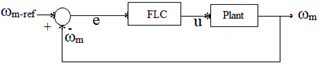
The fuzzy logic controller in this study utilizes rotor speed error and its variation as input parameters for the control strategy [23, 24]. The block diagram for the speed control system is displayed in Figure 2.
Figure 2. Block diagram for speed loop
Five triangular membership functions are employed for both the input and output variables of the Mamdani-type fuzzy inference system. These functions are defined as, NM: medium negative value, Z: zero, PM: medium positive value, PB: large positive value., offering a balanced linguistic representation for fuzzy logic reasoning. The input variables are the error e(t) and its change Δe(t), while the output represents the control signal to the rotor side converter (RSC).
The chosen range of [−80000,80000] for both inputs and output is not arbitrary but is based on simulations and analysis of the maximum expected rotor speed deviation and voltage fluctuation under extreme wind speed variations. This range is wide enough to capture the full dynamic envelope of system response, while ensuring resolution and sensitivity in control actions.
The rule base in Table 2 was initially structured using expert knowledge and then refined using an iterative trial-and-error tuning process during simulation.
Table 2. Fuzzy speed control rules
|
$\frac{d}{d x}$ |
e(t) |
NB |
NM |
Z |
PM |
PB |
|
NB |
|
NB |
Z |
NB |
Z |
Z |
|
NM |
|
Z |
NM |
NM |
Z |
Z |
|
Z |
|
NB |
NM |
Z |
PM |
PB |
|
PM |
|
Z |
Z |
PM |
PM |
PB |
|
PB |
|
Z |
Z |
PB |
PB |
PB |
Figure 3. Fuzzy membership function for input
This process involved observing the dynamic response (overshoot, settling time, and steady-state error) and adjusting rules to minimize performance deviations. Although empirical, this tuning strategy is a common and accepted method in fuzzy control design, especially when system dynamics are nonlinear and analytically complex. This approach provides a flexible, adaptive control mechanism suitable for the nonlinear behavior of DFIG systems, especially under wind fluctuations and grid disturbances.
For speed control utilizing a FLC technique, the membership functions for the input and output are illustrated in Figures 3 and 4, respectively.
Figure 4. Fuzzy membership function for output
3.1 Simulation of DFIG for RSC
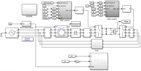
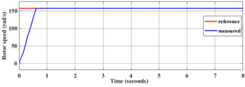
The entire system was simulated using MATLAB/Simulink to analyze its performance under various operational modes. The whole simulation system is depicted in Figure 5, which includes the generator side converter controller block, GSC controller block and DC-link voltage regulator. The fuzzy logic controller block is included under controller block of RSC and its sub block is shown in Figure 6. Figure 7 illustrates the simulated rotor speed.
For the generator to function under synchronous, sub-synchronous and super-synchronous conditions, the rotor speed is contrasted with the reference speed of 1500 rpm.
Initially, the generator operates at 90% of its rated speed from 0 t0 3.63 seconds. During this period, the measured speed closely aligns with the reference signal, with only slight deviation.
At 90% of the rated speed (142.8 rad/sec), the generator functions in sub-synchronous mode as its speed is lower than the normal speed. When the rotor speed changes at 3.63 seconds, the generator turns into a synchronous motor. The rated speed in this mode is 157 rad/sec. The measured signal smoothly tracks the set point from 3.63 to 5 seconds at a speed of 157 rad/sec, indicating that the generator is operating in synchronous mode.
The system transitions into super-synchronous operation between 5 and 8 seconds. During this period, the rotor speed surpasses the rated speed, reaching a set point of 172.7 rad/sec. The measured response tracks the reference speed signal, indicating stable control. The generated torque characteristics are presented in Figure 8. Initially, the reference input is set at 90% of the normal speed, enabling the generator to operate in sub-synchronous mode up to two seconds, where the rotor speed is at 1500 rpm. The torque reference is initially zero.
After two seconds, the torque gradually increases to 25% of its rated value, shifting toward negative torque. A perturbation is applied at the two-second mark, resulting in a slight torque variation. After six seconds, the generator starts behaving similarly to a motor, entering super-synchronous operation. The torque response adapts accordingly to the rotor speed changes, highlighting the system’s dynamic adaptability.
Figure 5. MATLAB/Simulink block diagram of the system
Figure 6. Simulink model for fuzzy logic block diagram
Figure 7. Rotor speed
Figure 8. The generated torque
Figure 9. d-axis rotor current
Figure 10. d-q axis reference voltages
Figure 11. Simulated rotor current in quadrature axis
Figure 12. Rotor current
To facilitate the simulation and regulate the current in the q-axis, the d-axis rotor current is kept at zero A, which is presented in Figure 9. The output of reference voltages are displayed in Figure 10. The currents in the d-q axis of rotor part are separated and regulated separately according to the vector control technique. As a result, the torque is directly related to the rotor current in the q-axis, whereas the rotor current in the d-axis regulates the reactive power of the stator winding. The simulated outcome of the q-axis rotor current is depicted in Figure 11. The three-phase rotor currents are displayed in Figure 12.
The rotor current signal is not smooth sinusoidal waveform because the rotor portion of the DFIG is coupled with power electronic converters. The generator's rotor speed variation has an impact on the simulated rotor current. In the supper synchronous area, the rotational current is switched from a-b-c to a-c-b. Figures in 13 and 4 illustrate the three phase stator currents and voltages respectively. Since the stator part of DFIG is directly connected with grid, the stator currents and voltages become purely sinusoidal with a 50Hz frequency.
Figure 13. Stator current
Figure 14. Stator voltage
Figure 15. DC bus voltage
Figure 16. d-axis grid current
Figure 17. q-axis grid current
Figure 18. Grid voltage references
3.2 Simulation of DFIG for GSC
As indicated in Figure 15, the DC-bus voltage stabilizes at 1200V after transient oscillations and accurately tracks the reference signal within one second. Similarly, the d-axis current smoothly follows the reference after initial fluctuations, indicating precise control and stable operation which is presented in Figure 16.
The simulation results in Figure 17 and 18 highlights the stable performance of the system. The grid current along q-axis being kept at zero confirms the successful elimination of reactive power exchange, which is a crucial requirement for achieving a unity power factor. Consequently, the grid voltage components behaved as expected. Due to the absence of reactive power demand the q-axis voltage stabilizes at zero and this ensures proper power transfer.
3.3 Simulation of speed control using FLC
When the FLC is used on the speed loop, the simulated output is shown in Figure 19. When compared to the conventional controller PI in this instance, the output is following the set point signal more efficiently, the settling time is shorter, and the maximum overshoot becomes zero. This shows fuzzy logic-based rotor speed control is quicker and more effective.
3.4 Simulation of 3-level Neutral Point Clamped (NPC)
To address the issue of harmonics, an LCL filter was incorporated between the power converter and the grid. This configuration fulfills the IEEE standards, ensuring efficient harmonic mitigation and improved system stability. By integrating the filter with three level NPC voltage source converter using SVPWM, the THD was minimized below 5% which is shown in Figure 20.
The output voltage for SPWM is typically expected to be around 88%, while for SVPWM, it is significantly higher due to better modulation schemes. The Total Harmonic Distortion for SPWM is usually around 30–50%, as this modulation method is less efficient in reducing harmonics compared to SVPWM [25], which yields much lower THD values. The THD for the 3-Level NPC inverter with SVPWM shows the best performance. when combined with the LCL filter, the THD is reduced to levels compliant with the IEEE 519 standard (<5%).
The LCL filter plays a significant role in reducing high-frequency harmonics that are not adequately mitigated by the inverter alone. This is why the THD values drop significantly when the filter is added.
The LCL filter effectively suppresses high-frequency components, contributing to a cleaner current waveform and improving overall system performance. This, in turn, helps to bring the THD within the acceptable limits for residential and industrial applications.
Figure 19. Proposed controller result of the rotor speed
Figure 20. THD and harmonic spectrum
This study presented a comprehensive control strategy for a DFIG-based wind energy conversion system to achieve optimal power transfer and system stability. A vector control approach was implemented to both RSC and GSC. The RSC was responsible for controlling rotor currents, regulating rotor speed, managing reactive power and ensuring torque control under synchronous, sub-synchronous and super-synchronous conditions. Meanwhile, the GSC ensured effective decoupling control of grid-side real and reactive power, while maintaining a stable DC-link voltage at 1200V and a power factor close to unity. A fuzzy logic controller was developed for the speed loop, enhancing system robustness and dynamic response. The proposed strategy demonstrated superior performance by reducing overshoot, minimizing settling time and ensuring reliable operation. The integration of a three-level NPC voltage source converter with an LCL filter and SVPWM effectively minimized harmonic distortion, maintaining compliance with IEEE standards.
[1] Ouhssain, S., Chojaa, H., Aljarhizi, Y., Al Ibrahmi, E., Hadoune, A., Maarif, A., Suwarno, I., Mossa, M.A. (2024). Performance optimization of a DFIG-based variable speed wind turbines by IVC-ANFIS controller. Journal of Robotics and Control (JRC), 5(5): 1492-1501. https://doi.org/10.18196/jrc.v5i5.22118
[2] Sayeh, K.F., Tamalouzt, S., Ziane, D., Benyahia, N., Belaid, S.L., Belkhier, Y. (2025). Real-time fuzzy logic-based direct power control for wind energy systems. Engineering Applications of Artificial Intelligence, 154: 110968. https://doi.org/10.1016/j.engappai.2025.110968
[3] Kasbi, A., Rahali, A. (2021). Performance optimization of doubly-fed induction generator (DFIG) equipped variable-speed wind energy turbines by using three-level converter with adaptive fuzzy PI control system. Materials Today: Proceedings, 47: 2648-2656. https://doi.org/10.1016/j.matpr.2021.05.406
[4] Yesgat, A.W., Salau, A.O., Kassahun, H.E. (2022). Fuzzy based sliding mode control of vector controlled multiphase induction motor drive under load fluctuation. Journal of Electrical and Electronics Engineering, 15(2): 98-105.
[5] Benbouhenni, H., Zinelaabidine, B., Belaidi, A. (2018). DFIG-based wind turbine system using three-level neural space vector modulation technique. Majlesi Journal of Mechatronic Systems, 7(2): 37-48.
[6] Mohammadi, J., Vaez-Zadeh, S., Afsharnia, S., Daryabeigi, E. (2014). A combined vector and direct power control for DFIG-based wind turbines. IEEE Transactions on Sustainable Energy, 5(3): 767-775. https://doi.org/10.1109/TSTE.2014.2301675
[7] Benbouhenni, H., Colak, I., Bizon, N., Mosaad, M.I., Tella, T.G. (2024). Power regulation of variable speed multi rotor wind systems using fuzzy cascaded control. Scientific Reports, 14(1): 16415. https://doi.org/10.1038/s41598-024-67194-4
[8] Wiam, A., Ali, H. (2019). Direct torque control-based power factor control of a DFIG. Energy Procedia, 162: 296-305. https://doi.org/10.1016/j.egypro.2019.04.031
[9] Board, I.P.E. (2011). Electrical System of a Variable Speed Wind Turbine. John Wiley & Sons, Inc., Hoboken, New Jersey.
[10] Benbouhenni, H., Boudjema, Z., Belaidi, A. (2018). Using three-level Fuzzy space vector modulation method to improve indirect vector control strategy of a DFIG based wind energy conversion systems. International Journal of Smart Grid, 2(3): 155-171.
[11] Kadi, S., Imarazene, K., Berkouk, E.M., Benbouhenni, H., Abdelkarim, E. (2022) A direct vector control based on modified SMC theory to control the double-powered induction generator-based variable-speed contra-rotating wind turbine systems. Energy Reports, 8: 15057-15066, https://doi.org/10.1016/j.egyr.2022.11.052
[12] Sabarad, J., Kulkarni, G.H. (2015). Comparative analysis of SVPWM and SPWM techniques for multilevel inverter. In 2015 International Conference on Power and Advanced Control Engineering (ICPACE), Bengaluru, India, pp. 232-237. https://doi.org/10.1109/ICPACE.2015.7274949
[13] Jenkal, H., Bossoufi, B., Boulezhar, A., Lilane, A., Hariss, S. (2020). Vector control of a Doubly Fed Induction Generator wind turbine. Materials Today: Proceedings, 30: 976-980. https://doi.org/10.1016/j.matpr.2020.04.360
[14] Djoudi, O., Belaid, S.L., Tamalouzt, S. (2023). Multilevel converter and fuzzy logic solutions for improving direct control accuracy of DFIG-based wind energy system. Periodica Polytechnica Electrical Engineering and Computer Science, 67(2): 136-148. https://doi.org/10.3311/PPee.21047
[15] Zamzoum, O., El Mourabit, Y., Errouha, M., Derouich, A., El Ghzizal, A. (2018). Power control of variable speed wind turbine based on doubly fed induction generator using indirect field‐oriented control with fuzzy logic controllers for performance optimization. Energy Science & Engineering, 6(5): 408-423. https://doi.org/10.1002/ese3.215
[16] Aydin, E., Polat, A., Ergene, L.T. (2016). Vector control of DFIG in wind power applications and analysis for voltage drop condition. In 2016 National Conference on Electrical, Electronics and Biomedical Engineering (ELECO), Bursa, Turkey, pp. 81-85.
[17] Wang, Y., Đukanović, S., Sarma, N., Djurović, S. (2023). Implementation and performance evaluation of controller signal embedded sensorless speed estimation for wind turbine doubly fed induction generators. International Journal of Electrical Power & Energy Systems, 148: 108968. https://doi.org/10.1016/j.ijepes.2023.108968
[18] Maafa, A., Mellah, H., Benaouicha, K., Babes, B., Yahiou, A., Sahraoui, H. (2024). Fuzzy logic-based smart control of wind energy conversion system using cascaded doubly fed induction generator. Sustainability, 16(21): 9333. https://doi.org/10.3390/su16219333
[19] Adnan, M.M., Sharma, A., Saravanan, T., Bhagat, R.K., Jolad, B., Naidu, K.K. (2024). Advanced control strategies for multilevel inverters in renewable energy systems: enhancing power quality and efficiency. E3S Web of Conferences, 591: 01013. https://doi.org/10.1051/e3sconf/202459101013
[20] Ramana, P.V., Rosalina, K.M. (2025). Optimizing weak grid integrated wind energy systems using ANFIS-SRF controlled DSTATCOM. Scientific Reports, 15(1): 13662. https://doi.org/10.1038/s41598-025-98872-6
[21] Baesmat, H.J., Bodson, M. (2018). Pole placement control for doubly-fed induction generators using compact representations in complex variables. IEEE Transactions on Energy Conversion, 34(2): 750-760. https://doi.org/10.1109/TEC.2018.2867630
[22] Spahic, E., Morren, J., Balzer, G., Michalke, G. (2007). Mathematical model of the double fed induction generator for wind turbines and its control quality. In 2007 International Conference on Power Engineering, Energy and Electrical Drives, Setubal, Portugal, pp. 642-647. https://doi.org/10.1109/POWERENG.2007.4380111
[23] Rached, B., Elharoussi, M., Abdelmounim, E. (2019). Fuzzy logic control for wind energy conversion system based on DFIG. In 2019 International Conference on Wireless Technologies, Embedded and Intelligent Systems (WITS), pp. 1-6. https://doi.org/10.1109/WITS.2019.8723722
[24] Sayeh, K.F., Tamalouzt, S., Ziane, D., Bekhiti, A., Belkhier, Y. (2025). Utilizing fuzzy logic control and neural networks based on artificial intelligence techniques to improve power quality in doubly fed induction generator‐based wind turbine system. International Journal of Energy Research, 2025(1): 5985904. https://doi.org/10.1155/er/5985904
[25] Kassahun, H.E., Salau, A.O., Mohammed, S.H. (2022). Comparative analysis of controllers for power system dynamic stability improvement. In 2022 International Conference on Decision Aid Sciences and Applications (DASA), pp. 1732-1736. https://doi.org/10.1109/DASA54658.2022.9765219