Khoi Nguyen Nguyen*![]() | Ngoc Vy Duong
| Ngoc Vy Duong![]()
© 2025 The authors. This article is published by IIETA and is licensed under the CC BY 4.0 license (http://creativecommons.org/licenses/by/4.0/).
OPEN ACCESS
The vehicle suspension system functions to mitigate vibration excitations from the road surface and ensure ride comfort. In the context of increasing demands for performance and safety in modern vehicle design, the development and analysis of accurate suspension dynamic models is essential to support both mechanical design and the development of control systems aimed at enhancing ride comfort. This study presents an entirely passive suspension system that operates solely through mechanical components, such as springs and dampers, with fixed parameters that cannot be adjusted. A dynamic model of a 5-degrees-of-freedom (DOF) suspension system for a half-electric vehicle in the longitudinal direction was developed based on Newton’s Second Law and simulated by using Matlab/Simulink. The simulation was conducted on random road following ISO 8608:2016 standards, a half sine road and a harmonic sinusoidal road. Simulation results indicate that the passive suspension system is capable of attenuating vibrations to a certain extent, ensuring ride comfort, as reflected by the RMS acceleration values falling within the acceptable comfort range defined by ISO 2631-1:1997 for whole-body vibration. However, its performance remains limited. This study may serve as reference data for analytical purposes, providing a foundational framework for the comparative analysis and performance assessment of systems employing control algorithms to enhance ride comfort.
passive suspension system, 5 DOF, ride comfort, vehicle vibration, Matlab/Simulink
During transportation vehicle operation, passenger comfort is paramount. Consequently, analyzing the impact of vibrations on occupants becomes an essential aspect that cannot be overlooked in vehicle dynamics and human response studies. Research on multi DOF suspension models has enabled a detailed representation of vehicle dynamics under vertical excitations induced by road surface irregularities.
As a result, extensive research efforts have been undertaken to analyze vehicle vibrations triggered by external stimuli, aiming to identify contributing factors and propose effective solutions for mitigating their impact. Research [1] concentrates on developing a suspension system for heavy duty trucks, with the goal of enhancing the mitigation of road surface-induced vibrations while ensuring the preservation of cargo stability. A quarter-vehicle model is employed to investigate four types of suspension systems: passive, semi-active, linear, and nonlinear configurations. A significant contribution of the research is the introduction of the Proportional Integral Derivative (PID) controller for the semi-active suspension system. The results indicate that this configuration, regulated by the developed control approach, delivers enhanced performance with respect to road compatibility and cargo protection. The paper [2] proposes a distinct and effective control approach, utilizing a quarter-car framework integrated with a PID controller. This system is evaluated via Matlab/Simulink simulations to optimize dynamic performance in response to road surface perturbations. To optimize control efficacy, the study [3] focuses on designing and assessing an innovative control algorithm, designated Sliding Mode - PID optimized via Fuzzy Logic (SMPIDF), for managing the operation of an active suspension system. The results indicate superior effectiveness in attenuating vehicle vibrations and improving dynamic characteristics. This study [4] focuses on improving the efficacy of vehicle suspension systems, specifically the active suspension in a quarter-car model, by implementing a Fractional Order PID (FOPID) controller refined through the Whale Optimization Algorithm (WOA) and Particle Swarm Optimization (PSO). The results reveal a substantial enhancement in the performance of the suspension system. Additionally, several studies extend the 3 DOF quarter-car active suspension model to incorporate driverseat dynamics, as exemplified in study [5]. In this work, the author formulates a 3 DOF model to investigate, design, and evaluate four distinct control strategies: PID, Linear Quadratic Regulator (LQR), Fuzzy Logic Controller (FLC), and Artificial Neural Network (ANN). The results of the research demonstrate that all four control methodologies significantly improve the efficacy of the 3 DOF active suspension system over its passive counterpart, enhancing both occupant comfort and vehicle maneuverability. An alternative approach presented in case [6] involves tuning the parameters of Model Predictive Control (MPC) and PID controllers using the PSO algorithm to manage the suspension system in a half-car 4 DOF model. Simulation results reveal a substantial enhancement in performance compared to both the passive suspension setup and the non-optimized MPC, particularly in minimizing suspension travel and improving ride comfort. Another research direction concerning the 4-DOF half-car suspension system is explored by the author in study [7], where the model is simulated within the horizontal plane. D'Alembert’s principle and the Runge-Kutta method are employed to formulate and analyze the dynamic behavior. The evaluation is based on load transfer ratio (LTR) and the roll angle disparity between the sprung and unsprung masses. Following the analysis, a stabilizer bar is incorporated to enhance the vehicle’s roll stability. The study [8] demonstrates that integrating a PID controller into the stabilizer bar of an active suspension system effectively reduces the rollover risk of liquid tank trucks, especially at critical liquid fill levels. The model was developed based on the Lagrange method and D'Alembert's principle. Simulation results indicate significant reductions in LTR and TRA during cornering and lane-change maneuvers. Further expanding on previous work, the paper [9] develops a 5 DOF active suspension system, focusing on the design and refinement of a robust state-feedback controller augmented by fuzzy logic. This integrated methodology, merging traditional state-feedback control with a fuzzy inference system, seeks to optimize the system's overall efficacy. The prominent findings indicate that integrating optimization algorithms such as Sine-Cosine, Particle Swarm Optimization (PSO), and Grey Wolf Optimizer (GWO) with fuzzy control significantly enhances control performance compared to previous models, including passive suspension, PID regulation, and adaptive control strategies. To enhance the realism of computational analysis, numerous studies employ full-car models to simultaneously simulate vertical oscillations, pitch, and roll dynamics, as well as the interaction between all four wheels and road-induced excitations. This comprehensive approach aims to improve ride comfort and operational safety. Ma et al. [10] implemented a 7 DOF SUV vehicle model utilizing a PID controller to mitigate body acceleration, dynamic tire loads, and suspension travel. A simulation scheme is developed using Matlab/Simulink and CarSim, incorporating a PID controller within the framework. Simultaneously, the random road input profile and the full-vehicle model are constructed using the CarSim platform. Simulation results indicate that the active suspension system, regulated by the PID controller, significantly improves overall vehicle efficacy, thereby enhancing occupant comfort and driving safety. Similar to study [10], research [11] also employs a full-car 7 DOF model but utilizes a Fractional Order Terminal Sliding Mode Controller (FOTSMC). This investigation demonstrates the application of the FOTSMC approach to enhance vibration control performance of the active suspension system in a complete vehicle model. Furthermore, the study [12] presents the framework of a Hybrid Fuzzy Controller engineered to optimize the balance between passenger comfort and road adhesion in a comprehensive vehicle active suspension model. The controller integrates two unique control approaches, each specifically tuned for either ride quality or tire traction, and implemented at each wheel as appropriate. The results show that simultaneous enhancement of ride comfort and road-holding performance is achievable with the proposed control strategy. Additionally, in study [13], the author employs a fuzzy PID controller and a Neural Network controller to regulate the vehicle's yaw rate. A 14 DOF vehicle model is implemented for design and analysis within the Matlab/Simulink environment. The obtained results demonstrate a marked improvement in vehicle performance with the integrated control systems compared to the uncontrolled configuration.
Whereas previous research has primarily concentrated on optimizing passive suspension parameters and formulating suspension control strategies to improve ride comfort and overall suspension performance. Nevertheless, there remains a significant need for studies that elucidate vibration transmission to vehicle occupants using more detailed dynamic models, in order to accurately identify and evaluate the factors influencing ride comfort. Although many studies have concentrated on active and semi-active suspension systems to enhance ride comfort and vehicle dynamic stability, these systems typically involve complex control algorithms and elevated implementation costs, which constrain their feasibility for deployment in mass-produced, economy-class vehicles. In particular, research utilizing passive suspension models with a 5 degrees-of-freedom (5 DOF) configuration remains scarce, despite the model’s ability to more accurately represent the coupled dynamic behavior between the sprung mass, unsprung masses, and the driver's seat under vertical road excitations. Consequently, this research aims to assess the ride comfort of a half-electric vehicle model in the longitudinal plane, with a focus on analyzing driverseat oscillations under road-induced excitation. The evaluation is based on the Root Mean Square (RMS) value of vertical acceleration transmitted to the occupant, in accordance with ISO 2631-1:1997 standards.
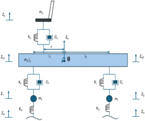
Figure 1 depicts the vibration model of a half electric vehicle with five degrees of freedom (5 DOF), designed on the longitudinal plane according to the vehicle's framework. The model assumes that the driver’s seat mass encompasses both the seat and the occupant, while the combined mass of the motor, battery, and chassis is regarded as the body mass, treated as a unified rigid entity. The model comprises four distinct mass elements: the front wheel (mf), the rear wheel (mr), the vehicle body (mb), and the driver’s seat (ms). The model does not consider lateral roll motion or yaw motion around the vertical axis, and it also neglects tire slip relative to the road surface. Additionally, nonlinear effects and complex forced excitations induced by road surface profiles are not considered.
Figure 1. Dynamic model of a half electric vehicle
The dynamic model shown in Figure 1 assumes that the vehicle body is a rigid mass mb, capable of pitching about its center of gravity with mass moment of inertia of the vehicle about the y-axis Iy. The front and rear suspension systems are represented by linear spring-damper elements, with stiffness coefficients kf, kr and damping coefficients cf, cr. The seat and driver are modeled as one ms, connected to the vehicle body via a spring of stiffness ks and a damper with damping coefficient cs. The front and rear wheels are considered as unsprung masses mf, mr, connected to the body through the suspension system and to the road surface via tire springs with stiffness Kt. The model also considers road excitations at each wheel, represented by the vertical displacement inputs Ztf and Ztr.
Based on Figure 1, by utilizing Newton's Second Law [14], the dynamic equations governing the motion are derived, resulting in the following set of expressions:
$m_f \ddot{Z}_1=-k_{t f}\left(Z_1-Z_{t f}\right)+k_f\left(Z_{b 1}-Z_1\right)+c_f\left(\dot{Z}_{b 1}-\dot{Z}_1\right)$ (1)
$m_r \ddot{Z}_2=-k_{t r}\left(Z_2-Z_{t r}\right)+k_r\left(Z_{b 2}-Z_2\right)+c_r\left(\dot{Z}_{b 2}-\dot{Z}_2\right)$ (2)
$\begin{aligned} & m_b \ddot{Z}_b=-k_f\left(Z_{b 1}-Z_1\right)-c_f\left(\dot{Z}_{b 1}-\dot{Z}_1\right)-k_r\left(Z_{b 2}-Z_2\right) \\ & -c_r\left(\dot{Z}_{b 2}-\dot{Z}_2\right)+k_s\left(Z_s-Z_{p s}\right)+c_s\left(\dot{Z}_s-\dot{Z}_{p s}\right)\end{aligned}$ (3)
$m_s \ddot{Z}_s=-k_s\left(Z_s-Z_{p s}\right)-c_s\left(\dot{Z}_s-\dot{Z}_{p s}\right)$ (4)
$\begin{aligned} & I_y \ddot{\theta}=l_1\left[k_f\left(Z_{b 1}-Z_1\right)+c_f\left(\dot{Z}_{b 1}-\dot{Z}_1\right)\right]-l_2\left[k_r\left(Z_{b 2}-Z_2\right)+c_r\left(\dot{Z}_{b 2}-\dot{Z}_2\right)\right]-r\left[k_s\left(Z_s-Z_{p s}\right)+c_s\left(\dot{Z}_s-\dot{Z}_{p s}\right)\right]\end{aligned}$ (5)
The vertical displacements of Zps, Zb1, and Zb2 are determined as follows:
$Z_{p s}=Z_b-r \theta$ (6)
$Z_{b 1}=Z_b-l_1 \theta$ (7)
$Z_{b 2}=Z_b+l_2 \theta$ (8)
Table 1. Basic parameters of electric vehicle
|
Symbols |
Values |
Symbols |
Values |
|
ms |
120 |
kr |
27300 |
|
mb |
846 |
cf |
1861 |
|
Iy |
1516 |
cr |
1861 |
|
mf |
47 |
ks |
1750 |
|
mr |
47 |
cs |
700 |
|
ktf |
238000 |
l1 |
1.29 |
|
ktr |
238000 |
l2 |
1.61 |
|
kf |
21000 |
r |
0.5 |
To evaluate the dynamics of a half electric vehicle model, the suspension system specifications and vehicle structure parameters are thoroughly defined. Table 1 outlines the critical parameters, referenced from the technical data in studies [15, 16]. These values are utilized in the simulation and dynamic assessment to effectively characterize the vehicle's oscillatory behavior in the longitudinal plane.
Parameters in Table 1 correspond to dynamic properties of the suspension system, such as mass of seat and driver, sprung mass, unsprung mass, geometric dimensions, stiffness, and damping. Their selection is based on values reported in previous studies [15, 16] in the field of vehicle dynamics.
In this study, different types of road excitations are used to simulate the roughness of the road surface.
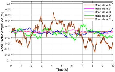
The ISO 8608 standard defines the classification of longitudinal road profiles based on power spectral density (PSD). This statistical description of road roughness can be used for both single-track and dual-track road simulations in computer models and laboratory testing environments. The PSD-based method has become a standard approach in automotive engineering, supporting the development of vehicles and their components in both the frequency and time domains [17]. To simulate random excitations acting on vehicle in motion, with vibrations that are stable over time, the first excitation function is based on the PSD of the vertical displacement of the road surface. This PSD is categorized from Class A to Class E, corresponding to road quality ranging from very good to poor, as presented in the study [18] according to the international standard ISO 8608:2016, and is presented by the following equation:
$\dot{Z}_s(t)=2 \pi n_o \mathrm{w}(t) \sqrt{G_q\left(n_o\right) v}-2 \pi f_o Z_R(t)$ (9)
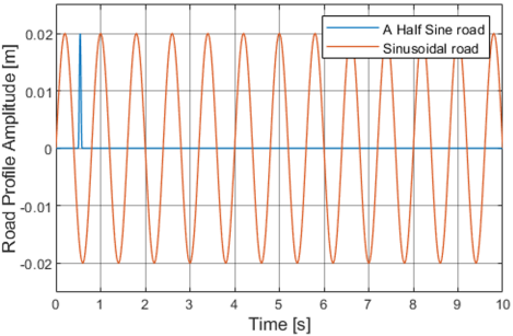
The second excitation function, researchers [19, 20] propose a roughness road profile modeled as a half-sine wave with an amplitude a and a length d:
$Z_{R 1}(t)=\left\{\begin{array}{lc}\frac{a}{2}\left(1-\cos \left(2 \pi \frac{v}{d}(t-0.5)\right)\right) & 0.5 \leq t \leq 0.5+\frac{d}{v} \\ 0 & \text { otherwise }\end{array}\right.$ (10)
Finally, the excitation function of harmonic sinusoidal road is described by the authors in the studies [20, 21] as follows:
$Z_{R 2}(t)=d_1 \sin \left(2 \pi \frac{v}{d_2} t\right)$ (11)
Table 2. Road profile parameters
|
Symbols |
Values |
Symbols |
Values |
|
$Z_R(t)$ |
- |
$f_o$ |
0.0628 |
|
$n_o$ |
0.1 |
a |
0.02 |
|
w(t) |
- |
d |
0.85 |
|
$G_q\left(n_o\right)$ |
$16.10^{-6}$ (Class A) $64.10^{-6}$ (Class B) $256.10^{-6}$ (Class C) $1024.10^{-6}$ (Class D) $4096.10^{-6}$ (Class E) |
d1 |
0.02 |
|
v |
10, 15, 20 |
d2 |
8 |
where, t is the vehicle's travel time across road surface types, the symbols are shown in Table 2.
The simulation results of the road profile are presented in Figure 2:
Figure 2. The road profiles
The International Organization for Standardization (ISO) 2631-1 provides guidelines concerning mechanical vibration and shock, with a primary focus on whole-body vibration assessment. Its main objective is to establish quantitative methods for evaluating the impact of vibration on human health, comfort, perception, and the potential contribution to health-related issues. ISO 2631-1 is widely adopted for assessing ride comfort in vehicle, utilizing vibration measurement data. In particular, the standard’s use of Root Mean Square (RMS) acceleration and frequency-weighted filtering serves as a fundamental approach for evaluating ride comfort [22]. To evaluate the simulation results, the RMS values of acceleration must be analyzed for distinct mass components, with particular focus on the driver's seat in this case. Through this, it is possible to clearly understand the impact from road excitation affecting ride comfort, while also being able to evaluate the ride comfort that the driver perceives when the vehicle is in motion. According to ISO 2631-1:1997 [23], the RMS value of vibration acceleration is determined by the following formula:
$a_w=\sqrt{\left[\frac{1}{T} \int_0^T a_w^2(t) d t\right]}$ (12)
where, aw is the RMS acceleration, m/s2; T is the execution time of the motion simulation process, s. aw(t) is the RMS value of the vibration acceleration of the motion at time t, m/s2.
Since the driver's seat mass is also subjected to road excitation, the RMS acceleration of driver’s seat determined by Eq. (12) can be compared with the reference RMS values in Table 3 [24] based on ISO 2631-1:1997 to evaluate ride comfort.
Table 3. Ride comfort estimation based on ISO 2631-1:1997 standard
|
The RMS Acceleration, m/s2 |
Ride Comfort Estimation |
|
< 0.315 |
Comfortable |
|
0.315 - 0.63 |
A little uncomfortable |
|
0.5 - 1.0 |
Fairly uncomfortable |
|
0.8 - 1.6 |
Uncomfortable |
|
1.25 - 2.5 |
Very uncomfortable |
|
> 2.0 |
Extremely uncomfortable |
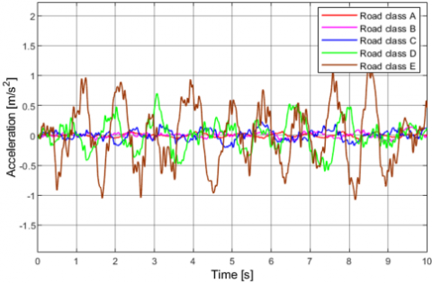
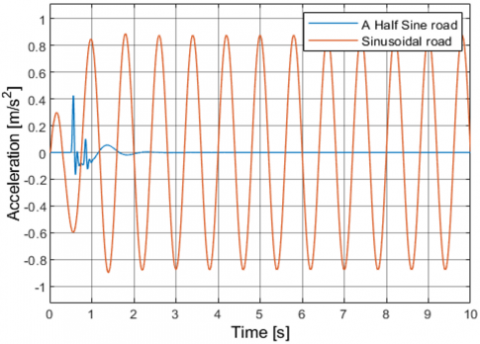
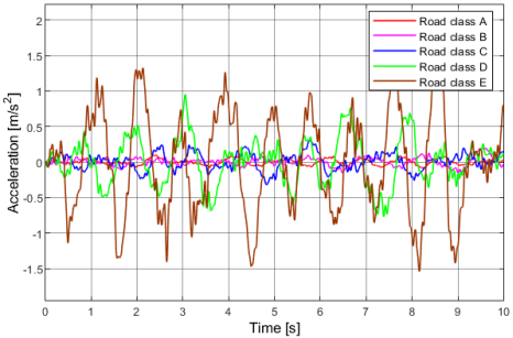
The vertical displacement acceleration of the driver's seat when the vehicle in motion obtained after the simulation process using Matlab/Simulink is shown in the following Figures 3, 4 and 5:
(a) Random road surface
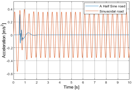
(b) A half sine road and harmonic sinusoidal road
Figure 3. Vertical acceleration of driver’s seat at a speed of 10 m/s
Based on the simulation results of vertical acceleration when the vehicle travels on random road at 10 m/s, the RMS acceleration values corresponding to road classes A to E, a half sine road, and harmonic sinusoidal road are respectively 0.027, 0.044, 0.083, 0.241, 0.503, 0.031, and 0.604 m/s². For road classes A to C and a half sine road profile, the vibration levels are very low and can be easily assessed as comfortable for the driver. At class D, the RMS value increases significantly but still complies with ride comfort requirements per ISO 2631-1:1997. However, at class E and the harmonic sinusoidal road with RMS accelerations of 0.503 and 0.604 m/s², prolonged exposure may cause driver discomfort.
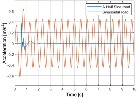
(a) Random road surface
(b) A half sine road and harmonic sinusoidal road
Figure 4. Vertical acceleration of driver’s seat at a speed of 15 m/s
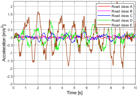
(a) Random road surface
(b) A half sine road and harmonic sinusoidal road
Figure 5. Vertical acceleration of driver’s seat at a speed of 20 m/s
At 15 m/s, the vertical vibration response at the driver’s seat shows increasing trend as the class of road transitions from A to E, but decreases sharply when operating on a half sine and harmonic sinusoidal roads, with RMS accelerations of 0.039, 0.060, 0.117, 0.330, 0.715, 0.025, and 0.323 m/s², correspondingly. Ride comfort begins to degrade noticeably at classes D and E, with Class E reaching a distinctly uncomfortable level for the driver. Although the seat’s RMS value on the harmonic sinusoidal road (0.323 m/s²) shows only marginal deviation from the ISO 2631-1:1997 threshold of 0.315 m/s², it still induces slight discomfort.
When the speed is increased to 20 m/s, the RMS acceleration values of random road class A to E, a half sine bump and a sinusoidal road, are 0.047, 0.073, 0.144, 0.399, 0.877, 0.020, and 0.256 m/s². The RMS values consistently increase with each road class and reach a maximum value in class E at 0.877 m/s², exceeding the comfort threshold for drivers according to the standard. The vibration amplitude is not only large but also exhibits multiple sharp peaks, reflecting strong road-induced impacts on the driver at high speeds. For random road of class D, although the RMS acceleration exceeds the ride comfort threshold, it generally does not cause excessive discomfort for the driver.
To facilitate the comparison of simulation results between different road excitations at the speeds of 10, 15, and 20 m/s, the RMS acceleration values at the driver’s seat are summarized in the Tables 4 and 5 below, making it easier compare with the ISO 2631-1:1997 thresholds in Table 3 for ride comfort estimation.
Table 4. RMS acceleration of the driver’s seat at 10, 15, and 20 m/s under random road profile
|
Velocity, m/s |
RMS Acceleration of the Driverseat, m/s2 |
|||||
|
Random Road Profile |
||||||
|
Class A |
Class B |
Class C |
Class D |
Class E |
||
|
10 |
0.027 |
0.044 |
0.083 |
0.241 |
0.503 |
|
|
15 |
0.039 |
0.060 |
0.117 |
0.330 |
0.715 |
|
|
20 |
0.047 |
0.073 |
0.144 |
0.399 |
0.877 |
|
Table 5. RMS acceleration of the driver’s seat at 10, 15, and 20 m/s under half sine road and harmonic sinusoidal road
|
Velocity, m/s |
RMS Acceleration of the Driverseat, m/s2 |
|
|
A Half Sine Road Profile |
Sinusoidal Road Profile |
|
|
10 |
0.031 |
0.604 |
|
15 |
0.025 |
0.323 |
|
20 |
0.020 |
0.256 |
When the speed increases, the RMS acceleration rises significantly on random roads (especially class D and E) but decreases on a half sine road, primarily due to the extended duration the vehicle remains in contact with the flat segment of the road profile at higher velocities. On a harmonic sinusoidal road, at a speed of 10 m/s, resonance occurs as the excitation frequency coincides with the system's natural frequency, causing the two wheels to oscillate in phase, resulting in an RMS acceleration of 0.604 m/s2. When the speed increases to 15 m/s, the excitation frequency shifts away from the resonant frequency, leading to potential anti-phase wheel oscillations and a reduction in RMS acceleration to 0.323 m/s2. At 20 m/s, the excitation frequency continues to rise, and while the oscillation phase becomes more favorable for cancellation, no resonance is triggered, resulting in a further decrease in RMS acceleration to 0.256 m/s². Thus, ride comfort is determined by a combination of factors, not only by velocity but also road profile, suspension characteristics, excitation frequency, and the system’s natural frequency.
The study develops a 5 DOF suspension model for a half electric vehicle, applying Newton’s Second Law to describe the vehicle’s longitudinal motion and analyze the effects of road excitation including random road based on ISO 8608:2016, a half sine road and harmonic sinusoidal road on ride comfort. Ride comfort is evaluated using the RMS acceleration specified in ISO 2631-1:1997 at speeds of 10, 15, and 20 m/s. Simulation results indicate that ride comfort at the driver’s seat remains within acceptable limits when traveling on random roads of Class A, B, and C, as well as a half sine road, across all tested speeds. However, excitation from Class D and E random roads and harmonic sinusoidal road generates RMS accelerations exceeding the ride comfort threshold, causing driver discomfort. While the model is based on linear assumptions, does not consider lateral roll motion or yaw motion or driver biomechanics, it remains sufficient for capturing the key dynamics within the scope of this study. The absence of experimental data for validation is also a noted limitation. The research can serve as a reference and input for further research on suspension system improvements or controller design to enhance ride comfort during vehicle operation.
|
ms |
Mass of seat and driver, kg |
|
mb |
Mass of body, kg |
|
Iy |
Mass moment of inertia of the vehicle about the y-axis, kgm2 |
|
mf |
Unsprung mass at the front axle, kg |
|
mr |
Unsprung mass at the rear axle, kg |
|
ktf |
Stiffness of the front tire, N/m |
|
ktr |
Stiffness of the rear tire, N/m |
|
kf |
Stiffness of the front suspension spring, N/m |
|
kr |
Stiffness of the rear suspension spring, N/m |
|
cf |
Damping coefficient of the front suspension, Ns/m |
|
cr |
Damping coefficient of the rear suspension, Ns/m |
|
cr |
Damping coefficient of the rear suspension, Ns/m |
|
ks |
Spring stiffness of the suspension system mounted beneath the driver’s seat, N/m |
|
cs |
Damping coefficient of the suspension system mounted beneath the driver’s seat, Ns/m |
|
l1 |
Distance from the vehicle’s center of gravity to the front axle, m |
|
l2 |
Distance from the vehicle’s center of gravity to the rear axle, m |
|
r |
Distance from the vehicle’s center of gravity to the driver’s seat, m |
|
$Z_R(t)$ |
The road excitation displacement at the time t |
|
$n_o$ |
Reference spatial frequency, m-1 |
|
W(t) |
Time domain Gaussian white noise signal |
|
$G_q(n)$ |
The reference PSD of the spatial frequency, m3 |
|
v |
The driving speed, m/s |
|
$f_o$ |
Cut-off frequency, Hz |
|
a |
Amplitude of a half sine road, m |
|
d |
The length of a half sine road, m |
|
d1 |
Amplitude of sinusoidal road, m |
|
d2 |
The length of the sinusoidal road, m |
|
aw |
The RMS acceleration, m/s2 |
|
T |
The execution time of the motion simulation process, s |
|
aw(t) |
The RMS value of the vibration acceleration of the motion at time t, m/s2 |
[1] Prasad, V., Pawaskar, D.N., Seshu, P. (2021). Controller design and multi-objective optimization of heavy goods vehicle suspension system by geometry-inspired GA. Structural and Multidisciplinary Optimization, 64(1): 89-111. https://doi.org/10.1007/s00158-021-02860-z
[2] Nguyen, V.T., Duong, N.H.L. (2022). Modeling and simulation of PID controller-based active suspension system for a quarter car model. Journal of Technical Education Science, 17(1): 111-120. https://doi.org/10.54644/jte.68.2022.1126
[3] Nguyen, T.A. (2023). Research on the Sliding Mode – PID control algorithm tuned by fuzzy method for vehicle active suspension. Forces in Mechanics, 11: 100206. https://doi.org/10.1016/j.finmec.2023.100206
[4] Karam, Z.A., Awad, O.A. (2020). Design of active fractional PID controller based on Whale’s optimization algorithm for stabilizing a quarter vehicle suspension system. Periodica Polytechnica Electrical Engineering and Computer Science, 64(3): 247-263. https://doi.org/10.3311/ppee.14904
[5] Bataineh, A., Batayneh, W., Okour, M. (2021). Intelligent control strategies for three degree of freedom active suspension system. International Review of Automatic Control, 14(1): 17-27. https://doi.org/10.15866/ireaco.v14i1.20057
[6] Pedro, J.O., Nhlapo, S.M., Mpanza, L.J. (2020). Model predictive control of half-car active suspension systems using particle swarm optimisation. IFAC-PapersOnLine, 53(2): 14438-14443. https://doi.org/10.1016/j.ifacol.2020.12.1443
[7] Nguyen, X.N., Tran, T.T. (2023). Rollover stability dynamic analysis of passenger vehicle in moving conditions. Mathematical Modelling and Engineering Problems, 10(1): 149-154. https://doi.org/10.18280/mmep.100116
[8] Nguyen, X.N., Tran, V.N., Vu, V.T., Dang, T.P. (2024). Active suspension with PID control for enhanced rollover stability in liquid tank trucks. Journal of Electrical Systems and Automation, 12(1): 45-53. https://doi.org/10.18280/jesa.570105
[9] Mahmoodabadi, M., Nejadkourki, N., Ibrahim, M.Y. (2024). Optimal fuzzy robust state feedback control for a five DOF active suspension system. Results in Control and Optimization,17: 100504. https://doi.org/10.1016/j.rico.2024.100504
[10] Ma, S., Li, Y., Tong, S. (2023). Research on control strategy of seven-DOF vehicle active suspension system based on co-simulation. Measurement and Control, 56(7-8): 1251-1260. https://doi.org/10.1177/00202940231154954
[11] Yuvapriya, T., Lakshami, P., Rajendiran, S. (2020). Vibration control and performance analysis of full car active suspension system using fractional order terminal sliding mode controller. Archives of Control Sciences, 30(2): 295-324. https://doi.org/10.24425/acs.2020.133501
[12] Van Tan, V. (2023). Two-layer parallel fuzzy logic controller design for semiactive suspension system with a full car model. Shock and Vibration, 2023(1): 7020462. https://doi.org/10.1155/2023/7020462
[13] Ahmed, A.A., Alshandoli, A.S. (2020). Using of neural network controller and fuzzy PID control to improve electric vehicle stability based on a 14-DOF model. In 2020 International Conference on Electrical Engineering (ICEE), pp. 1-6. https://doi.org/10.1109/icee49691.2020.9249784
[14] Wang, W., Tian, K., Zhang, J. (2020). Dynamic modelling and adaptive control of automobile active suspension system. Journal of Electrical Systems and Automation, 53(2): 297-303. https://doi.org/10.18280/jesa.530218
[15] Zakher, B.N., El Fahham, I.M., Elhadary, M., El-Gohary, M. (2024). The effect of road profile on the performance of a full car suspension model ride comfort. Journal of Engineering Research (JER), 8(4). Tanta University, Faculty of Engineering.
[16] Zhang, J., Yang, Y., Hu, M., Fu, C., Zhai, J. (2020). Model predictive control of active suspension for an electric vehicle considering influence of braking intensity. Applied Sciences, 11(1): 52. https://doi.org/10.3390/app11010052
[17] Peter, M. (2018) Simulated road profiles according to ISO 8608 in vibration analysis. Journal of Testing and Evaluation, 46(1): 405-418. https://doi.org/10.1520/JTE20160265
[18] Kopylov, S., Chen, Z., Abdelkareem, M.A. (2020). Acceleration based ground-hook control of an electromagnetic regenerative tuned mass damper for automotive application. Alexandria Engineering Journal, 59(6): 4933-4946. https://doi.org/10.1016/j.aej.2020.09.010
[19] Jiang, H., Wang, C., Li, Z., Liu, C. (2021). Hybrid model predictive control of semiactive suspension in electric vehicle with hub-motor. Applied Sciences, 11(1): 382. https://doi.org/10.3390/app11010382
[20] Nguyen, X.N., Tran, V.N., Vu, V.T., Dang, T.P., Tran, T.T. (2022). Analyze the influence of road profiles on the comfort of passengers in sleeper bus. In Proceedings of the 2nd International Conference on Advanced Technology & Sustainable Development, Ho Chi Minh City (Vol. 700000).
[21] Li, W., Wei, J., Du, H., Ning, D., et al. (2021). Event-triggered H∞ control for active seat suspension systems with state delay. Transactions of the Institute of Measurement and Control, 43(15): 3428-3437. https://doi.org/10.1177/01423312211021320
[22] Feng, C., Pang, C. (2022). Research on vibration of mechanical system based on MATLAB. Journal of Physics: Conference Series, 2195(1): 012050. https://doi.org/10.1088/1742-6596/2195/1/012050
[23] Pham, N.D., Tran, H.N., Tran, D., Nguyen, D.H. (2025). Ride comfort evaluation of an motorbike with random excitation by a multi body dynamic model. Journal of Physics Conference Series, 2949(1): 012042. https://doi.org/10.1088/1742-6596/2949/1/012042
[24] Ma, C., Wang, Z., Wu, T., Su, J. (2025). Investigation of the smoothness of an intelligent chassis in electric vehicles. World Electric Vehicle Journal, 16(4): 219. https://doi.org/10.3390/wevj16040219