Mohammed Jawad Mohammed*![]() | Tamarah Ayad Kareem
| Tamarah Ayad Kareem![]()
© 2025 The authors. This article is published by IIETA and is licensed under the CC BY 4.0 license (http://creativecommons.org/licenses/by/4.0/).
OPEN ACCESS
The fabrication of an Unmanned Air Vehicle (UAV) wing using a 3D printer and the study of vibration behavior were conducted in this research. The study of vibration behavior is an important factor to preserve the structures from destruction, especially when the frequency of the bodies is closed to the natural frequency. The aircraft airfoil was designed based on Naka 2416 and the wings were printed using PLE metal. Then, air currents were directed at speeds of 10, 15, and 20 m/s to study the effect of vibrations in order to find the frequency for each speed using a fan whose speed is controlled by an inverter and compare it to the natural frequency. Pitot-tube and accelerometer were used to measure the air speed and vibration, respectively. The results showed that the damping coefficient is relatively small (ζ=0.0644), indicating that the damping in the system is weak, which is in line with the design of UAV that need low damping to maintain a fast response during flight. Also, the wing frequencies reached up to 2.66 Hz and 5.66 at speeds of 20 m/s and 15 m/s, respectively were closest to the natural frequency of the UAV wings, which was 3.94 Hz, compared to the frequency at speed of 10 m/s. The results also showed that the difference in frequencies were due to the emergence of non-linear phenomena in addition to the aerodynamic and structural forces, which is called aeroelastic effects, which leads to dynamic instability.
3D printer, Naka 2416, structure vibration, Unmanned Air Vehicle
Aerial vehicles without a human operator are known as Unmanned Aerial Vehicles, or UAVs. UAVs are utilized extensively in both military and civilian applications worldwide [1, 2]. From cargo shipping and submission, topographical mapping, geological surveys, search and rescue operations, asset safety inspection, crop monitoring and spraying, and road inspection, UAVs have also demonstrated a number of beneficial applications in both commercial and governmental domains, even as a hobby for individuals [3, 4].
Vibration is a principal characteristic when analyzing many mechanical systems. Unchecked vibration, particularly when the natural frequency approaches the body frequency, can cause more maintenance problems and eventually structural collapse [5].
An airplane's wing is a vital component that supports the weight of the UAVs and provides lift. There are three stages to design the UAVs, which are conceptual, preliminary, and detailed design [6]. An UAVs wing's design must be able to support and transmit weight. It is made up of thin shell structures that can sustain twisting, bending, and compression stresses. Both transverse frames and longitudinal stiffening components support the structure. This robust design produces unwanted vibration despite its endurance because of the aerodynamic effect [7]. 3D printing, also known as additive manufacturing (AM), has become a viable substitute for conventional manufacturing techniques in the creation of UAV wings. Design and manufacture of UAV components are being revolutionized by 3D printing, which makes it possible to fabricate complicated geometries, reduces material waste, and provides design freedom [8]. For lightweight applications where strength and vibration resistance are crucial, 3D printing is especially appealing because of its capacity to modify material characteristics and integrate complex internal systems [9]. Nevertheless, further research is needed to determine how 3D printing factors affect the vibrational properties of UAV wings.
Numerous scholars worked on UAV wings, including investigating vibration analysis on the wing, airfoil forms, and UAV wing design. In order to examine the aerodynamic and stability performance, Kapsalis et al. used the Taguchi approach and Computational Fluid Dynamics (CFD) to develop the VTOL UAV wing [10]. The UAV wing was created by Pecho et al. [11] using a 3D printer and NACA2412 airfoil made of PLA. According to the findings, the wing structure was robust and resisted deformation. To determine the best wing structural design, Długosz and Klimek [12] employed a composite material to construct the UAV wing. Moreover, UAV wings have been presented for design using the numerical FEM model. Simsiriwong et al. [13] demonstrated how manufacturing tolerances, joint design, and material anisotropy all have a substantial impact on vibration characteristics. Bras et al. [14] demonstrated that designs may be further optimized for increased vibrational resistance by including numerical modeling and experimental validation into the production process .
In this work, a 3D printer using PLA material was utilized to manufacture the UAV wing using the NACA 2416 type. In order to control the vibration in the future, an experimental design was carried out at three different wind speeds in addition to collecting the vibration data for each speed by presenting the frequencies compared to the natural frequency.
The National Advisory Committee for Aeronautics (NACA) created the NACA 2416 airfoil design, which is seen in Figure 1 [15]. Numerous aircraft applications make extensive use of this airfoil profile, which offers several benefits such as its adaptability, efficiency, speed, and aerodynamic capacity. The NACA 2416 airfoil is best suited for low-to-moderate speed ranges, despite its primary design [16]. Airfoil NACA 2416 achieves an excellent drag and lift ratio, which increases the wing structure's strength and resistance to vibration at aerodynamic turbulence [17]. The NACA 2416 airfoil is seen in Figure 1.
Figure 1. NACA 2416 [15]
It should specify the wing structural parameters: span (s), tip chord (CT), and root chord (CR) in order to examine the wing design and dimensions based on NACA 2416. Many steps should be taken into consideration to design the UAVs wing. Firstly, Eq. (1) is used to compute the wing area (A) [15]:
$\mathrm{A}=0.5 * S *[C T+C R]$ (1)
where, S, CT and CR refer to the span, tip chord, and root chord, respectively. Secondly, the air ratio can be computed using [15]:
$\mathrm{AR}=\frac{S^2}{A}$ (2)
Thirdly, the tap ratio average (TA) can be determined using the following method [15]:
$T A=\frac{C T}{C R}$ (3)
Lastly, the A chord Taper ratio is determined using the formula below [15]
$\bar{C}=\frac{\mathrm{A}}{\mathrm{S}}$ (4)
For aerodynamic formulation, the overall mathematical model of the wing can be written as follows [15]:
$\mathrm{L}=\frac{1}{2} \rho \mathrm{~V}^2 \mathrm{SC}_L \,\alpha$ (6)
where, L refers to lift force, $\rho$ refers to air density, V refers into the air speed, $\mathrm{C}_L$ refers to the lift coefficient and $\alpha$ refers to angle of attack. The drag fore can be represented as [18]:
$\mathrm{C}=\frac{1}{2} \rho V^2 S C_D \alpha$ (7)
where, $C_D$ refers to the Drag coefficient. The resulting moment about the reference point is calculated from the following equation [19]:
$M=\frac{1}{2} \rho S C_M$ (8)
where, $C_M$ refers to moment coefficient.
One of the most researched and utilized materials is polylactic acid (PLA) filament, a biodegradable and renewable aliphatic organic polymer. Easy manufacturing and biodegradability using Fused Deposition Modeling (FDM) technology are two of PLA filament's many advantages. Many difficult forms and geometries may be constructed using PLA filament [20]. The mechanical properties of the material used for the wing in this work are listed in Table 1 [21].
Table 1. PLA mechanical properties [19]
|
Property |
Units |
Values |
|
Polymer density |
kg/m3 |
1210-1250 |
|
Tensile Strength |
N/m2 |
21-60 × 106 |
|
Modulus of Tensile |
GPa |
0.35-3.5 |
|
Specific Strength of Tensile |
kNm/kg |
16.8-48 |
|
Modulus of Specific Tensile |
kNm/kg |
280-2800 |
|
Melting Temperature |
℃ |
150-162 |
To guarantee that the experimental work was done correctly and precisely, several devices and sensors were employed. These gadgets can be described as follows: an Ender-3 3D printer employed to print the wing structure. 10 m/s, 15 m/s, and 20 m/s as wind speeds were measured by an anemometer of the Proskit type MT-4615. A DF-5 centrifugal fan is used to create wind speeds. The speeds were controlled by MU5t inverter. Pitot-static tube used to measure wind speed, while an MPU6050 accelerometer used to measure acceleration. Finally, an Arduino Mega and Nano used to record acceleration and wind speed.
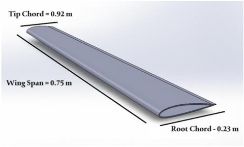
The NACA 2416 airfoil has been used to study the behavior and performance of a UAV wing. The wing's dimensions were described as a wingspan, rood chord and tip chord which equal to 75.2 cm, 23.6 cm and 9.2 cm, respectively, to assess the wing's properties at various speeds. The aircraft wing specifications are displayed in Table 2, and the SolidWorks program's design for the UAV wing is displayed in Figure 2.
Table 2. Aircraft wing specifications
|
Specifications |
Values |
|
Area |
0.1233 m2 |
|
Aspect Ratio (AR) |
4.5 |
|
Mean Chord |
0.1644 |
|
Average of Taper Ratio |
0.25 |
|
Wall Thickness |
5 mm |
|
Wingspan |
0.75 m |
|
Model of Wing Type |
Trapezoidal |
Figure 2. UAV wing's geometry
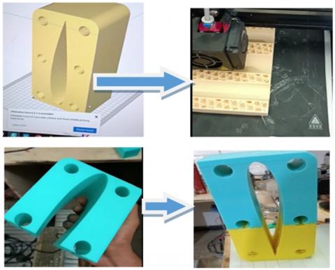
The wing was printed in four sections using an Ender 3 3D printer once the measurements were established and the drawings were finalized in SolidWorks. A plastic wire reel and adhesive were needed for assembly, and each item took 14 hours to print. Using sandpaper, the wing was sanded from 60 degrees to 80, 180, and 360 degrees in order to create a smooth surface. Water-based sandpaper is used to fill in any fine pores that remain after sanding and automobile putty have been used to remove any pores from the surface. Lastly, the gray rust oleum was applied to the wing. The wing has been fixed from one side using a carrier or holder. The holder has two symmetrical pieces, six screw holes, and an inside wing-like form.
Regarding the nozzle temperature, the optimal printing temperature for PLA ranged from 190 to 220℃. A low temperature (<190℃) will result in poor interlayer adhesion and breakage. A high temperature (>220℃) will result in excessive flow, material buildup on the nozzle, and surface deterioration. The print bed temperature ranged from 50 to 70℃. A low temperature (<50℃) will result in poor first-layer adhesion and warping of the edges. A high temperature (>70℃) may cause slight distortions in the final piece.
Figure 3 depicts the wing fabrication after 3D printing to coating, and Figure 4 depicts the wing holder.
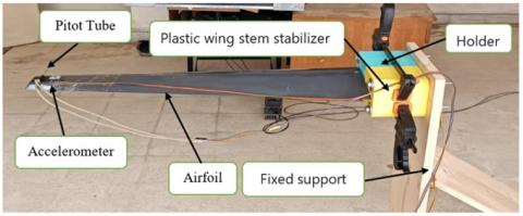
Vibration from wind across the surface of a solid plastic wing has been investigated in the University of Technology, Baghdad's Electromechanical Laboratory. A pitot static tube was used to measure the air velocity at the point of computing the vibration generated by the vortices, while an anemometer was utilized to measure the air velocity flowing over the wing. While Arduino MEGA is used to receive data from the accelerometer, Arduino Nano is utilized to send data from the Pitot static tube air speed sensor to the computer. To capture the most vibration, the accelerometer position has been optimized and placed near the end of the wing. Additionally, the wing's natural frequency, vibration from the fluid passing through at three different speeds, and the velocity of air exiting a centrifugal fan controlled by an inverter by varying the electric current's frequency and fixing the wing with a fixed wooden support and connecting it with a plastic part were all calculated. The 3D-printed wing with built-in sensors and the centrifugal fan with inverter are seen in Figures 5 and 6, respectively.
In order to analyze the aerodynamic characteristics, Figures 7-12 show the lift and drag forces for all proposed speeds (10 m/s, 15 m/s and 20 m/s) that were chosen based on the Iraqi Agrometeorological Center, where the wind speed in Iraq reached up to 20 m/s.
Figure 3. Aircraft wing 3D printing
Figure 4. Holder of 3D printing
Figure 5. Sensor-equipped experimental rig with supports
Figure 6. Combined centrifugal fan and inverter
Figure 7. Lift coefficient at 10 m/s
Figure 8. Drag coefficient at 10 m/s
Figure 9. Lift coefficient at 15 m/s
Figure 10. Drag coefficient at 15 m/s
Figure 11. Lift coefficient at 20 m/s
Figure 12. Drag coefficient at 20 m/s
Based on the angle of attack, the lift coefficient remains constant at all three speeds, approximately 1.7. This is consistent with the scientific explanation that the lift coefficient changes with the angle of attack when speed changes. This is due to the constant flow pattern around the wing, which, in turn, maintains a constant pressure distribution across the wing surface. On the other hand, the drag coefficient decreases as speed increases. At 10 m/s, the drag coefficient was 0.045 while at 15 m/s was 0.04 and 0.03 at 20 m/s. the drag coefficient values indicate that the flow has become more stable.
Following the impact test, the natural frequency of the wing was obtained using the decremental logarithm. Figure 13 displays the whole vibration amplitude. Figure 14 displays the wing's natural frequency.
It was observed that the amplitude ranges from -0.15 to 0.2 m/s2 over the duration of more than ten seconds. Also, the wing was stiff, and the natural frequency had a one-mode form and was 3.94 Hz. It is observed in Figure 7 that the vibration decreased rapidly, indicating that the wings have good damping properties that reduce the effect of excessive vibrations. moreover, this design is stable and safe for the UAV structures, as it has taken into consideration the dynamic and aerodynamic factors. The damping coefficient is relatively small (ζ=0.0644), means that the wing will vibrate several times before the vibrations completely dissipate, making it difficult to control the aircraft accurately at high speeds or during sharp manipulations. Moreover, the low damping ration indicates that the damping in the system is weak, which is in line with the design of UAV that need low damping to maintain a fast response during flight.
Figure 13. Wind-induced wing vibration amplitude
Figure 14. The natural frequency of wing
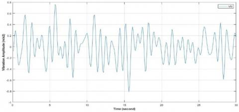
To investigate the vibration and frequencies that correspond to the wind speed experienced during flight, three different wind speeds were applied to the wing. The vibration amplitude and wing frequency at a wind speed of 10 m/s are displayed in Figures 15 and 16. The frequency value was 13.33 Hz, and the vibration ranged from -0.8 to 0.75 m/s2.
The vibration amplitude and wing frequency at a wind speed of 15 m/s are displayed in Figures 17 and 18. The range of vibration amplitudes increased from -0.185 to 0.18 m/s2 when the air velocity increased from 10 to 15 m/s, and the frequency value was 5.66 Hz.
Figure 15. Amplitude of vibration at 10 m/s
Figure 16. The frequency magnitude at 10 m/s
Figure 17. Amplitude of vibration at 15 m/s
Figure 18. The frequency magnitude at 15 m/s
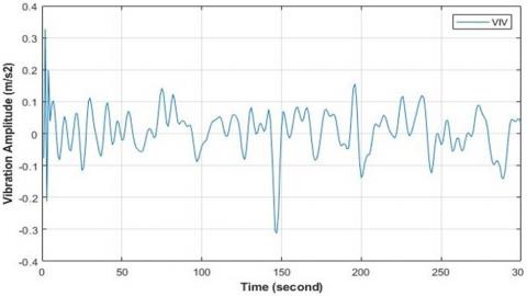
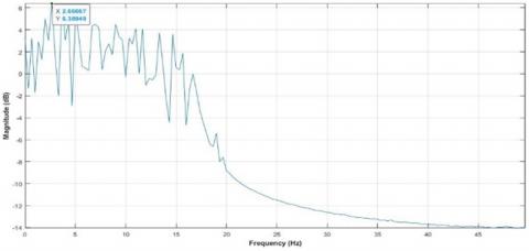
The wing frequency and vibration amplitude at a wind speed of 20 m/s are displayed in Figures 19 and 20. When the impulsive air velocity of the wing was raised to 20 m/s, the vibration frequency value was 2.66 Hz, and the vibration amplitude range was between -0.31 and 0.33 m/s2.
Figure 19. Amplitude of vibration at 20 m/s
Figure 20. The frequency magnitude at 20 m/s
While varying responses have been seen as a result of random vibration, the amplitude of wing vibration increased as wind speed rose. When the wind speed was 20 m/s, the frequency that was closest to the natural frequency occurred. The return to many components is the primary explanation for this phenomenon. Dynamic loading was the first element; as air speed increases, so does the dynamic pressure push on the wing. This modifies the wing-structure system's aeroelastic stiffness, which affects its inherent frequencies. Wing twisting and deflection are examples of phenomena that become more noticeable at greater airspeeds. The connection of structural and aerodynamic forces, known as aeroelastic effects, causes these interactions to alter the natural frequencies. Lastly, nonlinear phenomena like flutter or significant deflections may appear at particular speeds. These impacts have the potential to cause dynamic instability or drastically change the frequencies.
Fabricating the UAV wing and studying the vibration effect at different speeds have been investigated in this work. 3D printing technology used to build the UAV wing based on NACA 2416 airfoil design. After 3D printing, the rig needs to some operational processes, such as slandering to get smooth surface and collect results accurately. The created vortices above and lower the wing working on vibrating the wing with different behaviors due to different speed wind applied. The results showed that proposed design of wing based on NAKA 2416 was proper for UAV to get a fast response. The first conclusion is the lift coefficient remains constant approximately at different wind speeds unless layer separation occurrence due to the flow form and pressure distribution on the wing being constant. Moreover, drag coefficient reduced at increasing of wind speeds due to the flow being stable. Also, the vibration amplitude increased with increasing the wind speeds. The damping ratio (ζ) for the system was 0.0644 and referred that the system making it difficult to control the aircraft accurately at high speeds. The frequency values change with air speed due to the interplay between aerodynamic and structural factors. The frequency at wind speed 10 m/s was 13.33 Hz, and the vibration ranged from -0.8 to 0.75 m/s2. While the frequency at wind speed 15 m/s was 5.66 Hz, and the vibration ranged from -0.185 to 0.18 m/s2. Finally, air velocity of the wing was raised to 20 m/s, the vibration frequency value was 2.66 Hz, and the vibration amplitude range was between -0.31 and 0.33 m/s2. The closer frequencies happened at the wind speeds of 20 m/s and 15 m/s, respectively.
[1] El Adawy, M., Abdelhalim, E.H., Mahmoud, M., Mohamed, I.H., Othman, M.M., ElGamal, G.S., ElShabasy, Y.H. (2023). Design and fabrication of a fixed-wing Unmanned Aerial Vehicle (UAV). Ain Shams Engineering Journal, 14(9): 102094. https://doi.org/10.1016/j.asej.2022.102094
[2] Atencio, E., Plaza-Muñoz, F., Muñoz-La Rivera, F., Lozano-Galant, J.A. (2022). Calibration of UAV flight parameters for pavement pothole detection using orthogonal arrays. Automation in Construction, 143: 104545. https://doi.org/10.1016/j.autcon.2022.104545
[3] Romero-Chambi, E., Villarroel-Quezada, S., Atencio, E., Muñoz-La Rivera, F. (2020). Analysis of optimal flight parameters of Unmanned Aerial Vehicles (UAVs) for detecting potholes in pavements. Applied Sciences, 10(12): 4157. https://doi.org/10.3390/app10124157
[4] Biglia, A., Grella, M., Bloise, N., Comba, L., Mozzanini, E., Sopegno, A., Pittarello, M., Dicembrini, E., Alcatrão, E.L., Guglieri, G., Balsari, P., Aimonino, R.D., Gay, P. (2022). UAV-spray application in vineyards: Flight modes and spray system adjustment effects on canopy deposit, coverage, and off-target losses. Science of the Total Environment, 845(1): 157292. https://doi.org/10.1016/j.scitotenv.2022.157292
[5] Agrawal, P., Dhatrak, P., Choudhary, P. (2021). Comparative study on vibration characteristics of aircraft wings using finite element method. Materials Today: Proceedings, 46: 176-183. https://doi.org/10.1016/j.matpr.2020.07.229
[6] Sahraoui, M., Boutemedjet, A., Mekadem, M., Scholz, D. (2024). Automated design process of a fixed wing UAV maximizing endurance. Journal of Applied Fluid Mechanics, 17(11): 2299-2312. https://doi.org/10.47176/jafm.17.11.2647
[7] Abdulameer, H.A., Wasmi, H.R. (2015). Vibration control analysis of aircraft wing by using smart material. Innovative Systems Design and Engineering, 6(8): 7-42.
[8] Goh, G.D., Agarwala, S., Goh, G.L., Dikshit, V., Sing, S.L., Yeong, W.Y. (2017). Additive manufacturing in unmanned aerial vehicles (UAVs): Challenges and potential. Aerospace Science and Technology, 63: 140-151.
[9] Kapsalis, S., Panagiotou, P., Yakinthos, K. (2021). CFD-aided optimization of a tactical blended-wing body UAV platform using the Taguchi method. Aerospace Science and Technology, 108: 106395. https://doi.org/10.1016/j.ast.2020.106395
[10] Chung, P.H., Ma, D.M., Shiau, J.K. (2019). Design, manufacturing, and flight testing of an experimental flying wing UAV. Applied Sciences, 9(15): 3043. https://doi.org/10.3390/app9153043
[11] Pecho, P., Ažaltovič, V., Kandera, B., Bugaj, M. (2019). Introduction study of design and layout of UAVs 3D printed wings in relation to optimal lightweight and load distribution. Transportation Research Procedia, 40: 861-868. https://doi.org/10.1016/j.trpro.2019.07.121
[12] Długosz, A., Klimek, W. (2018). The optimal design of UAV wing structure. In AIP Conference Proceedings, Lublin, Poland, pp. 13-16. https://doi.org/10.1063/1.5019124
[13] Simsiriwong, J., Sullivan, R. W. (2012). Experimental vibration analysis of a composite UAV wing. Mechanics of Advanced Materials and Structures, 19(1-3): 196-206.
[14] Bras, M., Warwick, S., Suleman, A. (2022). Aeroelastic evaluation of a flexible high aspect ratio wing UAV: Numerical simulation and experimental flight validation. Aerospace Science and Technology, 122: 107400. https://doi.org/10.1016/j.ast.2022.107400
[15] Di Angelo, L., Di Stefano, P. (2014). An evolutionary geometric primitive for automatic design synthesis of functional shapes: The case of airfoils. Advances in Engineering Software, 67: 164-172. https://doi.org/10.1016/j.advengsoft.2013.10.002Get rights and content
[16] Hwas, A.M., Hatab, A.M. (2020). Effects of design parameters of wind turbine on airfoil coefficients using grey-based Taguchi method. Journal of Multidisciplinary Engineering Science and Technology, 7(12): 13103-13109.
[17] Moulton, B.C., Hunsaker, D.F. (2024). Analytic solutions for volume, mass, center of gravity, and inertia of wing segments and rotors of constant density. Aerospace, 11(6): 492. https://doi.org/10.3390/aerospace11060492
[18] Güzelbey, İ.H., Eraslan, Y., Doğru, M.H. (2019). Effects of taper ratio on aircraft wing aerodynamic parameters: A comparative study. European Mechanical Science, 3(1): 18-23. https://doi.org/10.26701/ems.487516
[19] Laiche, A., Boulahia, A. (2022). Mathematical modelling and simulation analysis of an aircraft wing using SimMechanics. Mathematical Modelling of Engineering Problems, 9(3): 796-802. https://doi.org/10.18280/mmep.090328
[20] Farah, S., Anderson, D.G., Langer, R. (2016). Physical and mechanical properties of PLA, and their functions in widespread applications—A comprehensive review. Advanced Drug Delivery Reviews, 107(15): 367-392. https://doi.org/10.1016/j.addr.2016.06.012
[21] Mabbrur, M.A.M., Hafidz El Amien, N.P., Syaifer, N.S., Hidayat, A., Nadzir, S.F. (2020). UAV wing structure with 3D printed PLA filament wing spar. International Journal of Mechanical Engineering and Robotics Research, 9(3): 464-469.