Anh Tuan Le![]() | Nguyen Thi Lan
| Nguyen Thi Lan![]() | Nhu Y Do
| Nhu Y Do![]() | Ho Viet Bun*
| Ho Viet Bun*![]()
© 2025 The authors. This article is published by IIETA and is licensed under the CC BY 4.0 license (http://creativecommons.org/licenses/by/4.0/).
OPEN ACCESS
Line-start permanent magnet synchronous motors (LSPMSM) are recognized for their numerous advantages, such as high efficiency and the ability to line-start, and are being researched for application in electric drive systems currently utilizing low-efficiency motors. Permanent magnets (PM) can be considered a source of self-excited magnetic field. For the motor to operate efficiently, the magnetic field generated by the magnets must be sufficiently large, meaning the size and type of magnets must be appropriate. Since LSPMSM still have a squirrel-cage rotor, the area available for positioning the PM is reduced, making the design of magnet placement more challenging compared to traditional PMSMs. Finding the optimal size to minimize material usage while achieving suitable operational characteristics is a crucial task in the motor design process. Therefore, this paper focuses on analyzing the thickness parameter of the magnets and its impact on the back-electromotive force and power factor. The research is conducted through theoretical analysis, simulation using the software applying finite element method, and experimentation on a 2.2 kW motor. The research findings also serve as important scientific guidance in selecting appropriate PM sizes for optimal operational characteristics.
permanent magnet synchronous motors, LSPMSM, back-electromotive force, PM, simulation and experimentation
Today, in the context of dwindling fossil energy sources and the growing issue of environmental pollution becoming a global concern, the use of energy-saving and efficient technologies is gaining attention from countries. Additionally, electric motors are devices that convert electrical energy into mechanical energy, consuming over 40% of the total electricity generated. Therefore, the use of high-efficiency electric motors for electric drive systems is a significant area of research [1, 2].
Line-start permanent magnet synchronous motors (LSPMSM) are recognized for their many advantages, such as high efficiency and the ability to line-start without the need for additional starting devices like traditional permanent magnet synchronous motors (PMSM) [3, 4]. In terms of construction, because LSPMSMs still have a squirrel-cage rotor, the area available for positioning the permanent magnets (PM) is reduced, making the design of magnet placement more challenging compared to PMSMs. The PM can be viewed as a source of self-excited magnetic field in LSPMSMs. The magnetic field generated by the PM must be sufficiently large, meaning that the size and type of PM must be appropriately selected for the motor to operate efficiently, which is considered one of the critical factors in the design of LSPMSMs [5, 6]. On the other hand, the assessment of the magnetic field generated by the PM in LSPMSMs can be evaluated through the investigation of back electromotive force (B-EMF) of the motor. A more sinusoidal EMF waveform leads to better operational quality of the LSPMSM [7]. Research on the values and waveforms of B-EMF in motors using PMs is currently of significant interest to many authors. In the other research, the finite element method (FEM) and equivalent magnetic circuit method are used to determine the distribution of the electromagnetic field to analyze magnetic saturation characteristics in the motor [8]. Based on flux density and magnetic vector potential, the B-EMF values are calculated using both methods, and the results are compared and analyzed. The calculations show that both methods are consistent, demonstrating effectiveness and utility for the design and performance analysis of PMSMs.
Additionally, a rotor design solution is presented to improve the total harmonic distortion (THD) component of the B-EMF waveform (B-EMFW) [9]. The results show that with the proposed solution applied to a 3.7 kW axial flux PMSM, the THD value of the B-EMF decreases from 11.5% to 5% by selecting the optimal rotor shift angle. In addition, the impact of the arrangement of PMs on the performance characteristics of LSPMSMs has been demonstrated [10, 11]. The findings indicate that performance characteristics, including B-EMF, are significantly influenced by the arrangement of PM in the rotor.
In reference [12], the impact of B-EMF on the performance of PM synchronous generators (PMSG) is analyzed. This differs from improving EMF by selecting the optimal rotor displacement angle [9] or using a specific magnet arrangement [10, 11]. This research aims to examine the influence of the thickness and material of the PMs on the B-EMF value of an 18-slot 16-pole PMSG. The paper seeks to determine the optimal thickness and type of magnets to achieve the highest B-EMF output. Additionally, the research results indicate that the highest B-EMF value is obtained when the magnet thickness is 6 mm.
In addition to solutions for improving B-EMF through optimal design approaches [9], magnet arrangements [10, 11], or magnet thickness [12], many other factors affecting EMF have also been researched. In references [13, 14], the impact of the operating modes of the distribution network on the performance parameters of LSPMSM, significantly affecting the waveform and value of the B-EMF, is also a focus of research.
In references [15, 16], the effects of coil asymmetry and changing pole on the operating characteristics, including the impact on the B-EMF of the LSPMSM motor are investigated. In reference [17], the influence of different types of PMs on the operating characteristics, specifically the B-EMF of the LSPMSM, is analyzed. The research results indicate that for each size and available magnetic circuit, there exists a suitable type of PM that minimizes the THD of the B-EMF waveform (B-EMFW). In reference [18], a new method and algorithm to analyze the impact of temperature parameters on the B-EMFW of the LSPMSM is proposed. Additionally, the results reveal that for PMSMs, the B-EMFW should be as sinusoidal as possible to achieve the lowest torque ripple [18]. This paper examines the effects of four common manufacturing defects on the B-EMF: the magnetization level of the magnets, the position and width of the magnets, and the angular displacement between the magnet blocks during installation. In reference [19], it is observed that the starting capability of the LSPMSM can be significantly improved by enhancing the torque during the startup process. This can be achieved by adjusting the B-EMF value during the motor's operation. The research results analyzed the ratio of optimal rotor/stator pole numbers to obtain an appropriate B-EMF value in the design.
The analyses above indicate that many factors affect the B-EMF characteristics of the LSPMSM during the design process. It can be said that there are currently not many studies investigating the impact of varying the thickness of PMs magnets on the B-EMF characteristics and power factor (PF) of the LSPMSM. Therefore, the content of this paper focuses on analyzing the influence of magnet thickness parameters during the design process on the B-EMF characteristics and PF of the LSPMSM motor assuming the magnetic circuit is not saturated. The research results were obtained through theoretical analysis, simulations using software applying finite element method, and experiments on a physical model of a 2.2 kW, 4-pole LSPMSM. Additionally, the research results provide important scientific guidance for selecting appropriate PM sizes to ensure the LSPMSM has optimal operating characteristics.
2.1 Mathematical model of LSPMSM
The mathematical model of LSPMSM includes equations for voltage, flux, and mechanical torque with the assumption that the magnetic circuit is not saturated. The mathematical model of LSPMSM is specifically as follows [20, 21]:
Stator, rotor voltage and flux equations:
$\left\{\begin{array}{l}u_{d s}=r_1 i_{d s}+\frac{d \Psi_{d s}}{d t}-\omega_r . \Psi_{q s} \\ u_{q s}=r_1 i_{q s}+\frac{d \Psi_{q s}}{d t}+\omega_r . \Psi_{d s}\end{array}\right.$ (1)
$\left\{\begin{array}{l}u_{d r}^{\prime}=r_{d r}^{\prime} i_{d r}^{\prime}+\frac{d \Psi_{d r}^{\prime}}{d t}=0 \\ u_{q r}^{\prime}=r_{q r}^{\prime} i_{q r}^{\prime}+\frac{d \Psi_{q r}^{\prime}}{d t}=0\end{array}\right.$ (2)
$\left\{\begin{array}{l}\Psi_{ds}=\left(L_{l s}+L_{m d}\right) i_{ds}+L_{m d} i_{d r}^{\prime}+\Psi_m^{\prime} \\ \Psi_{q s}=\left(L_{l s}+L_{m q}\right) i_{q s}+L_{m q} i_{q r}^{\prime}\end{array}\right.$ (3)
$\left\{\begin{array}{l}\Psi_{d r}^{\prime}=L_{l r}^{\prime} i_{d r}^{\prime}+L_{m d}\left(i_{d s}+i_{dr}^{\prime}\right)+\Psi_m^{\prime} \\ \Psi_{qr}^{\prime}=L_{l r}^{\prime} i_{q r}^{\prime}+L_{m q}\left(i_{q s}+i_{q r}^{\prime}\right)\end{array}\right.$ (4)
where, $\omega_r$-rotor angular velocity; $\Psi_m^{\prime}$-stator flux generated by the PMs; Lls-Leakage inductance of the stator winding; Lmd and Lmq are magnetizing inductances of d, q axes; ids, iqs, i'dr, i'qr – stator and rotor current of d, q axes.
The electromagnetic torque of the LSPMSM is determined:
$M_{e l}=\frac{3}{2} \cdot p \cdot\left[\underbrace{\left(L_{m d} \cdot i_{d r}^{\prime} \cdot i_{q s}-L_{mq} \cdot i_{q r}^{\prime} \cdot i_{d s}\right)}_{ {Induction \,\,Torque }} +\underbrace{\Psi_m^{\prime} \cdot i_{q s}}_{ {Excitation\,\,Torque }}+\underbrace{\left(L_{m d}-L_{m q}\right) \cdot i_{d s} \cdot i_{q s}}_{ {Re luc tan ce \,\,Torque }}\right]$ (5)
Tind, Texc, Trel - the induction, excitation and reluctance of torque component. The electromagnetic torque:
${{T}_{el}}={{T}_{ind}}+{{T}_{\text{ex}c}}+{{T}_{rel}}$ (6)
2.2 Analytical calculation model of Back-EMF of LSPMSM
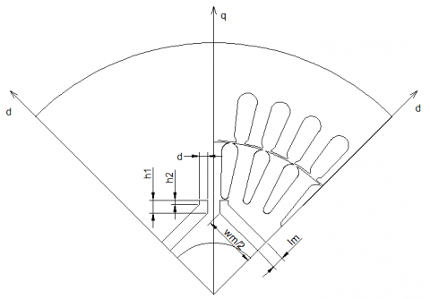
Consider a LSPMSM motor - 2p=4, which is constructed as shown in Figure 1.
Figure 1. Configuration of the LSPMSM motor, 2p = 4
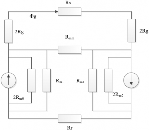
The equivalent magnetic circuit diagram of the LSPMSM, constructed in Figure 1 for calculating B-EMF using the analytical method, is illustrated in Figure 2 [22, 23].
Figure 2. Equivalent magnetic circuit of LSPMSM [23]
where, Rg - reluctance of the air gap, Rm0 - reluctance of the PM rod, Rml - reluctance of the magnetic barrier gap at the PM pole, Rmm - reluctance of the connecting bridge. The reluctance components of the magnetic circuit are determined [24].
${{R}_{g}}=\frac{{{k}_{C}}.g}{{{\mu }_{0}}.{{A}_{g}}}$ (7)
${{R}_{m0}}=\frac{{{l}_{_{m}}}}{{{\mu }_{0}}.{{\mu }_{rec}}.{{A}_{m}}}$ (8)
${{{R}}_{{ml}}}=\frac{4.\text{d}}{{{\mu }_{0}}.{{l}_{r}}.({{h}_{1}}+{{h}_{2}})}$ (9)
where, kC - carter coefficient, g - length of the air gap, α - ratio of pole arc/pole pitch, r1 - inner radius of the stator, lr - length of the rotor steel core, lm - thickness of the PM in the direction of magnetization, h1 - the top edge of the flux barrier, h2 - the bottom edge of the flux barrier, d -the thickness of the flux barrier, μ0, μrec - permeability of vacuum and relative permeability of the PM, Am = wm.lr - area of the PM, Ag - effective cross-section of the air gap.
${{A}_{g}}=\alpha .\frac{{{r}_{1}}.{{l}_{r}}.\pi }{p}$ (10)
Flux density in the air gap:
${{B}_{g}}=\frac{{{A}_{m}}/{{A}_{g}}}{1+\beta (1+2\eta +4\lambda )}{{B}_{r}}$ (11)
where, Coefficient $\lambda$ is defined:
$\lambda =\frac{1+1/\beta +2.\eta }{2.(\frac{{{A}_{m}}}{{{A}_{bdg}}}).(\frac{{{B}_{r}}}{{{B}_{s}}})-4}$ (12)
where, Abdg = t.lr, t - length of the connecting bridge, Bs- saturated flux density of the rotor steel core, Br – remanence of PM. Coefficients $\beta$, $\eta$ are determined:
$\beta =\frac{{{R}_{g}}}{{{R}_{m0}}}$ (13)
$\eta =\frac{{{R}_{m0}}}{{{R}_{ml}}}$ (14)
Fundamental magnetic flux amplitude of one pole generated by the PM:
${{\Phi }_{M1}}=\frac{{{D}_{s}}.{{l}_{r}}}{p}.\frac{4}{\pi }.\sin (\alpha .\pi /2).{{B}_{g}}$ (15)
The total linkage flux of the stator winding generated by the PM is determined:
${{\Psi }_{M}}={{k}_{w}}.{{N}_{ph}}.{{\Phi }_{M}}=\frac{4.D.{{l}_{r}}}{\pi }(\frac{{{k}_{w1}}{{N}_{ph}}}{p})\sin (\frac{\alpha \pi }{2}){{B}_{s}}$ (16)
So, B-EMF value generated by the PM is defined:
${{E}_{0}}=\frac{2\pi }{\sqrt{2}}.{{k}_{w}}.{{N}_{ph}}.{{\Phi }_{M}}.f=\frac{2\pi }{\sqrt{2}}.f.{{\Psi }_{M}}$ (17)
2.3 Analytical calculation model of Back-EMF of LSPMSM
The preliminary calculation of the dimensions of the PM in LSPMSM is typically based on the minimum volume of the magnet used [5].
${{V}_{m}}=\frac{2.{{k}_{ocf}}.{{k}_{fd}}(1+{{k}_{EC}}).{{P}_{out}}}{{{\pi }^{2}}.\xi .2.p.f.{{B}_{r}}.{{H}_{c}}}$ (18)
where, kocf is the overload capacity factor, kfd is the magnetization form factor, kEC is the EMF factor, and ξ is the magnet utilization factor, Pout is output rated power, f is the input frequency, Br and Hc are the remanence and the coercive force of PM respectively.
The LSPMSM has a squirrel-cage structure, as analyzed, which reduces the area available for the placement of the PM, particularly concerning the width of the PM. Therefore, there will be a maximum limit on the width of the PM that can be accommodated on the rotor (wmax). From the volume of the magnet Vm, the maximum width of the magnet wmax can be used to calculate the minimum thickness of the magnet lmin:
${{l}_{\min }}=\frac{{{V}_{m}}}{{{\text{w}}_{\text{max}}}.{{l}_{r}}}$ (19)
Thus, the size of the PM has a significant impact on the B-EMF characteristics of the LSPMSM motor. Additionally, the calculation of the magnet's thickness depends heavily on empirical coefficients. When compared to the width wm, the thickness of the magnet will be calculated to vary within a narrower range; however, it can be observed that its impact on the value of Vm is substantial. This will significantly affect the operational characteristics of the LSPMSM motor. Analyzing the influence of B-EMF due to the size of the magnet will aid in selecting an appropriate size for the PM. Through this selection, parameters such as efficiency and B-EMF will achieve the desired values in the design.
3.1 Parameters of the LSPMSM
The study was conducted on a 2.2 kW LSPMSM motor model, with 2p = 4, voltage (Y/Δ) 380/220V. The design parameters of the motor are shown in Table 1.
Table 1. LSPMSM parameters [25]
|
Parameters |
Symbol |
Value |
Unit |
|
Stator outer diameter |
Din |
154 |
mm |
|
Stator inner diameter |
Dout |
104 |
mm |
|
Rotor outer diameter |
D’ |
103 |
mm |
|
Rotor shaft diameter |
Dt |
28 |
mm |
|
Stator steel material |
Steel 1008 |
|
|
|
Number of stator slots |
Z1 |
36 |
slots |
|
Number of rotor slots |
Z2 |
28 |
slots |
|
Air gap length |
g |
0.5 |
mm |
|
Power supply voltage |
Un |
380/220 |
VAC |
|
Power supply frequency |
f |
50 |
Hz |
|
Magnet material |
|
NdFeB-N40 |
|
|
Magnet dimensions |
lr × lm × wm |
70 × 5 × 33 |
mm |
Properties of NdFeB-N40 PMs are shown in Table 2.
Table 2. Properties of NdFeB-N40 [26]
|
Parameters |
Symbol |
Value |
Unit |
|
Remanence |
Br |
1270 |
mT |
|
Coercivity |
Hcb |
951 |
kA/m |
|
Intrinsic coercivity |
Hcj |
955 |
kA/m |
|
Maximum energy product |
BHmax |
318 |
kJ/m3 |
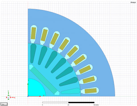
With the design parameters as shown in Table 1, a motor model was constructed using the software applying FEM Ansys/Maxwell, as illustrated in Figure 3.
Figure 3. Model of LSPMSM 2.2 kW, 2p = 4 in Ansys/Maxwell
The research scenario in this paper was conducted by varying the thickness of the magnet from lm = 4.0 to 6.0 mm, with an increment of 0.5 mm, to investigate the variation of B-EMF generated by the PM.
3.2 Phase Back-EMF
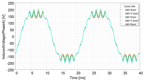
The results of the B-EMF characteristics survey of the LSPMSM when varying the wire thickness from 4.0 to 6.0 mm, with an increment of 0.5 mm, are presented in Figure 4.
Figure 4. B-EMFW in steady-state time
The waveform of the B-EMF of the motor in steady state is not sinusoidal but has clipped edges and peaks containing sawtooth shapes as shown in Figure 4. This is due to the magnetic field predominantly passing through the stator teeth of the motor, causing the magnetic field through the windings to be influenced by this factor. The FFT analysis of the B-EMFW reveals the harmonic components of the LSPMSM, as shown in Figure 5.
Figure 5. FFT analysis of Phase B-EMF of LSPMSM
The B-EMFW contains many odd harmonic components, as analyzed in Figure 5. Among the harmonic orders, significant harmonic components include the 3rd, 13th, and 15th orders. To evaluate the harmonics of the B-EMFW, the THD index is used. In addition to the THD index, ΔE% represents the deviation between the amplitude of the fundamental waveform and the nominal phase voltage of the power supply system used to assess the B-EMF of the LSPMSM [27, 28].
$\Delta E \%=\left|\frac{E_{1 N B}-220}{E_{1 N B}} 100 \%\right|$ (20)
where, E1NM is the effective value of the B-EMF of the fundamental waveform. The results of the harmonic component analysis corresponding to the cases of magnet width are presented in Table 3.
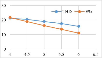
The results in Table 3 indicate that the thickness of the magnet significantly affects the generation of various harmonic components in the EMF, which causes torque ripple in the LSPMSM. In addition, as the width dimension lm increases from 4.0 mm to 6.0 mm, the ratio of the 3rd harmonic component decreases from 34.3 to 24.9. However, the 13th and 15th harmonic components increase from 9.2 to 10.3 and from 13.3 to 15.2, respectively. Additionally, the THD value also decreases, improving the vibration levels of the LSPMSM motor. As the thickness of the PM increases, both THD and ΔE% gradually decrease, reaching optimal values when the thickness lm= 6 mm. The rate of variation of THD and ΔE% is illustrated by the graph in Figure 6.
Table 3. FFT analysis of the harmonic components of the B-EMFW
|
lm (mm) |
1st |
3rd |
13th |
15th |
THD |
ΔE% |
|
4.0 |
180 |
34.3 |
9.2 |
13.3 |
21.3 |
21.8 |
|
4.5 |
185 |
33.4 |
9.5 |
13.8 |
20.4 |
19 |
|
5.0 |
189 |
31.4 |
9.7 |
14.2 |
19 |
16.2 |
|
5.5 |
194 |
28.7 |
10 |
14.6 |
17.6 |
13.7 |
|
6.0 |
198 |
24.9 |
10.3 |
15.2 |
15.7 |
11 |
Figure 6. THD and ΔE% versus thickness
The rate of variation of the error ΔE% with respect to thickness tends to be faster than the improvement of THD with respect to the thickness of the PM, as shown in Figure 6.
3.3 Current characteristics
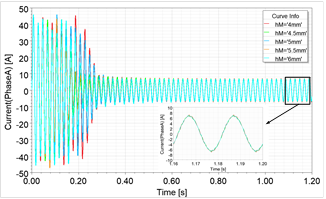
The current characteristics of the LSPMSM in the case of varying the magnet thickness are presented in Figure 7.
Figure 7. Current phase characteristics of LSPMSM
The paper uses the THD current index (THDi) to evaluate the level of harmonic generation in the current of the LSPMSM. THDi is determined [29, 30]:
$TH{{D}_{i}}=\,\frac{\sqrt{\sum\limits_{n=2}^{\infty }{I_{n}^{2}}}}{{{I}_{1}}}\,100%$ (21)
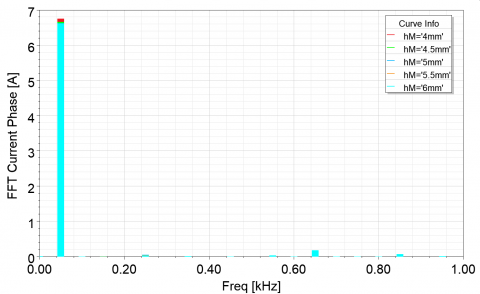
The results of the THDi analysis in cases of varying the thickness of the PM obtained harmonic components in steady-state time as shown in Figure 8.
Figure 8. FFT analysis of current waveforms.
The FFT analysis results of current waveforms in steady-state time are shown in Table 4.
Table 4. FFT current waveform of the LSPMSM
|
lm (mm) |
THDi %- Phase A |
|
4.0 |
3.11 |
|
4.5 |
3.21 |
|
5.0 |
3.22 |
|
5.5 |
3.15 |
The results in Table 4 indicate that when the thickness of the PM changes, the level of THDi also varies, reaching a maximum of THDimax = 3.22 at a thickness of lm = 5 mm and a minimum of THDimin = 3.11 at a thickness of lm = 4 mm.
3.4 Power factor characteristics
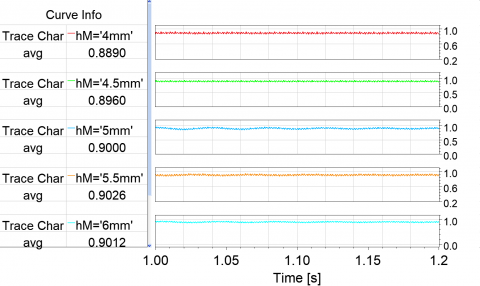
The PF is an important parameter of the LSPMSM. In the case of varying the thickness of the PM, the PF of the motor in the steady-state time is presented in Figure 9.
Figure 9. Power factor (cos$\varphi$) of LSPMSM
Thus, at the steady-state time corresponding to each value of lm, there will be a corresponding PF value. Figure 10 shows the PF values corresponding to different lm values.
From the PF characteristics of the LSPMSM motor investigated using the FEM, it is observed that with the same magnet width, the maximum PF occurs at a magnet thickness of lm = 5.5 mm with cos φmax = 0.926.
Figure 10. Power factor of the LSPMSM
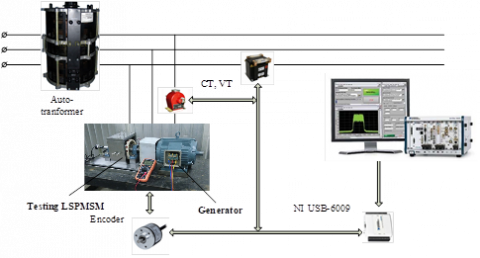
The research team fabricated a 2.2 kW LSPMSM motor for testing. In the experiment, the authors chose a magnet thickness of lm = 5.5 mm. The schematic of the experimental measurement setup was conducted in the laboratory, as shown in Figure 11. Some characteristics of the tested LSPMSM will be measured by connecting the motor to a computer via the NI USB-6009 card. The speed characteristics will be measured using the encoder type Autonics E40S6-3600-3-N-24 3600 P/R 12-24V 6mm, while the current and voltage signals will be measured using the current transformer type CT0.6 - 150/5A - 5VA - Cl 0.5 - N1 from EMIC and the voltage transformer type CHINT NDK 50VA IEC (380/220-36/24/12/6). In addition, the LIOA S3-4325 16.5 kVA three-phase autotransformer is used to adjust the input power supplied to the testing motor.
Figure 11. Testing diagram of LSPMSM
Figure 12. Phase back EMF waveform of testing LSPMSM
The experimental LSPMSM is connected to a generator, which is also an LSPMSM (generator). The LSPMSM (generator) operates at the same speed as the experimental LSPMSM, corresponding to 1,500 rpm. To measure the B-EMF characteristics, the process involves powering the LSPMSM (generator), where the LSPMSM-generator acts as the primary motor, driving the experimental LSPMSM to rotate at synchronous speed. The output of the experimental LSPMSM is open-circuit. The waveform measured at the terminals of the experimental LSPMSM will represent the B-EMF. The waveform of the B-EMF of the LSPMSM is measured and displayed using LabVIEW DAQ software implemented by the research team. The waveform of experimental B-EMF results in steady-state time are shown in Figure 12.
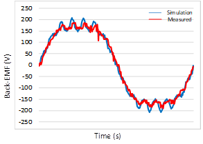
Comparing with the simulation results obtained in Figure 5 with lm = 5.5 mm, the combined results for both the simulation and actual measurement are shown in Figure 13.
Figure 13. Waveform measured experimental and FEM simulated of B-EMF
The experimental results indicate that the B-EMFW of the LSPMSM is not sinusoidal; it has a truncated shape and exhibits a sawtooth pattern due to the influence of the tooth and stator slot configuration. The experimental and measurement results in Figure 13 also show similarities. Additionally, the error in EMF between the experimental and simulated values is ΔE = 4%, indicating a good alignment between theory and experiment when studying the effect of magnet width on the parameters of the LSPMSM.
The LSPMSM motor is known for its many advantages, such as high efficiency and the ability to line-start without the need for additional devices like PMSMs. However, since the LSPMSM still has a squirrel cage in the rotor, the area for arranging PMs is reduced, making the design of the magnet arrangement more challenging compared to PMSMs. PMs are a source of magnetism in PMSMs, so for the motor to operate efficiently, the magnetic field generated by the PM must be sufficiently strong, meaning that the size and type of PM are crucial factors. Additionally, the magnetic field generated by the PM can be assessed through the examination of the B-EMF of the LSPMSM. The more sinusoidal the B-EMFW is, the better the operational parameters of the LSPMSM will be. This paper analyzes the parameters related to the thickness of the PM and its impact on the B-EMF characteristics of the LSPMSM. The theoretical analysis results indicate that the B-EMF of the LSPMSM depends on many parameters, especially the thickness of the PM, which affects the characteristics, including the B-EMF of the LSPMSM.
This paper employs the FEA method to evaluate simulations for a 2.2 kW LSPMSM motor with 2p = 4. The simulation results indicate that the thickness of the magnets significantly affects the B-EMF characteristics. It influences the harmonic components present in the B-EMFW, which causes fluctuations in the torque of the LSPMSM. As the thickness of the PMs increases, the THDi value and ΔE% gradually decrease, reaching optimal values when the thickness lm = 6 mm. The investigation of the variation rate of the error E% with respect to thickness tends to improve faster than the THDi value improvement with respect to the thickness of the PM. The analysis of the current characteristics also shows that as the thickness of the PM changes, the level of THD of the current also changes, reaching a maximum THD of THDimax = 3.22 at a thickness of lm = 5 mm and a minimum THD of THDimin = 3.11 at a thickness of lm = 4 mm.
Additionally, through simulations and experiments, it can be concluded that with the same width of the magnets, the maximum PF corresponds to a magnet thickness of lm = 5.5 mm and cosφmax = 0.926. The evaluation on the experimental model yields results that are consistent with the simulations, with an error of 4% between the two methods. From the above analysis, for the studied motor, a thickness of lm = 5.5 mm can be chosen as the design parameter, where the fundamental frequency value of B-EMFW approaches its maximum value while providing the highest PF in the steady-state time.
[1] Lin, B., Li, Z. (2020). Is more use of electricity leading to less carbon emission growth? An analysis with a panel threshold model. Energy Policy, 137: 111121. https://doi.org/10.1016/j.enpol.2019.111121
[2] Saidur, R., Mahlia, T.M.I. (2010). Energy, economic and environmental benefits of using high-efficiency motors to replace standard motors for the Malaysian industries. Energy Policy, 38(8): 4617-4625. https://doi.org/10.1016/j.enpol.2010.04.017
[3] Dinh, B.M., Tien, H.M. (2016). Maximum efficiency design of line start permanent magnet synchronous motor. In 2016 IEEE International Conference on Sustainable Energy Technologies (ICSET), Hanoi, Vietnam, pp. 350-354. https://doi.org/10.1109/ICSET.2016.7811808
[4] Tuan, L.A., Y, D.N., Khanh, N.T. (2025). Studying the Effect of Voltage Unbalance on the Working characteristics of LSPMSM. Journal Européen des Systèmes Automatisés 58 (1): 65-74. https://doi.org/10.18280/jesa.580108
[5] Elistratova, V. (2015). Optimal design of line-start permanent magnet synchronous motors of high efficiency. Doctoral dissertation, Ecole Centrale de Lille.
[6] Le Anh, T., Bien, T.T., Xuan, C.N., Do Anh, T., Do Nhu, Y. (2024). Analysis of permanent magnet demagnetization during the starting process of a line-start permanent magnet synchronous motor. Engineering, Technology & Applied Science Research, 14(6): 17900-17905. https://doi.org/10.48084/etasr.8576
[7] Simón-Sempere, V., Burgos-Payán, M., Cerquides-Bueno, J. R. (2013). Influence of manufacturing tolerances on the electromotive force in permanent-magnet motors. IEEE Transactions on Magnetics, 49(11): 5522-5532. https://doi.org/10.1109/TMAG.2013.2269906
[8] Cao, Y., Li, Q., Yu, L. (2009). Analysis and calculation of the electromagnetic field in permanent magnet synchronous motor based on ANSYS. In 2009 First International Conference on Information Science and Engineering, Nanjing, China, pp. 133-136. https://doi.org/10.1109/ICISE.2009.299
[9] Mirzahosseini, R., Darabi, A., Assili, M. (2020). Analytical and experimental analysis of Back EMF waveform of a TORUS-type non-slotted axial flux permanent magnet synchronous machine with shifted rotor. Measurement, 156: 107620. https://doi.org/10.1016/j.measurement.2020.107620
[10] Thuy, T.B., Cuong, N.X., Do Nhu, Y. (2023). Effect of permanent magnet structure on working characteristics of lspmsm 3000 rpm. IOP Conference Series: Earth and Environmental Science, 1275(1): 012049. https://doi.org/10.1088/1755-1315/1275/1/012049
[11] Do, N.Y., Le, T.A., Ngo, X.C. (2022). Effect of permanent magnet structure on the performance of LSPMSM with a power of 22 kW and 3000 rpm. IOP Conference Series: Earth and Environmental Science, 1111(1): 012047. https://doi.org/10.1088/1755-1315/1111/1/012047
[12] Abidin, A., Ramadhan, M.A.M., Rizki, A. (2024). Effect of magnet thickness and width variation on back EMF of 18-Slot 16-Pole permanent magnet synchronous generator. Applied Engineering, Innovation, and Technology, 1(1): 39-46. https://doi.org/10.62777/aeit.v1i1.11
[13] Paramonov, A., Oshurbekov, S., Kazakbaev, V., Prakht, V., Dmitrievskii, V. (2023). Investigation of the effect of the voltage drop and cable length on the success of starting the line-start permanent magnet motor in the drive of a centrifugal pump unit. Mathematics, 11(3): 646. https://doi.org/10.3390/math11030646
[14] Tabora, J.M., Correa dos Santos Júnior, L., Ortiz de Matos, E., Mota Soares, T., Arrifano Manito, A.R., de Lima Tostes, M.E., Holanda Bezerra, U. (2023). Exploring the effects of voltage variation and load on the electrical and thermal performance of permanent-magnet synchronous motors. Energies, 17(1): 8. https://doi.org/10.3390/en17010008
[15] Jedryczka, C., Wojciechowski, R.M., Demenko, A. (2014). Finite element analysis of the asynchronous torque in LSPMSM with non-symmetrical squirrel cage winding. International Journal of Applied Electromagnetics and Mechanics, 46(2): 367-373. https://doi.org/10.3233/JAE-141947
[16] Lin, M., Li, D., Zhao, Y., Ren, X., Qu, R. (2018). Comparison of different types of pole-changing line-start permanent magnet motors. In 2018 XIII International Conference on Electrical Machines (ICEM), Alexandroupoli, Greece, pp. 2051-2057. https://doi.org/10.1109/ICELMACH.2018.8507188
[17] Thuy, T.B., Tuan, L.A., Nhu Y, D., Cuong, N.X. (2023). Influence of the NdFeB permanent magnet on working characteristics of LSPMSM. In International Conference on Engineering Research and Applications, hai Nguyen, Vietnam, pp. 61-67. https://doi.org/10.1007/978-3-031-62235-9_8
[18] Baranski, M., Szelag, W., Lyskawinski, W. (2022). Modelling and experimental verification of temperature effects on back electromotive force waveforms in a line start permanent magnet synchronous motor. COMPEL-The International Journal for Computation and Mathematics in Electrical and Electronic Engineering, 41(5): 1491-1504. https://doi.org/10.1108/COMPEL-07-2021-0228
[19] Tian, M., Karimi, H. R., Li, Y., Wang, X., Zhao, W. (2023). Calculation of no-load induced electromotive force of pole changing line-start permanent magnet synchronous motor. IET Electric Power Applications, 17(8): 1030-1040. https://doi.org/10.1049/elp2.12320
[20] Y, D.N., Thuy, T.B., Tuan, L.A., Cuong, N.X. (2024) Rotor configuration for improved working characteristics of lspmsm in mining applications. Natsional'nyi Hirnychyi Universytet. Naukovyi Visnyk, 1(3):79-86. https://doi.org/10.33271/nvngu/2024-3/079
[21] Mahmoudi, A., Roshandel, E., Kahourzade, S., Vakilipoor, F., Drake, S. (2024). Bond graph model of line-start permanent-magnet synchronous motors. Electrical Engineering, 106(2): 1667-1681. https://doi.org/10.1007/s00202-022-01654-w
[22] Isfahani, A.H., Sadeghi, S. (2008). Design of a permanent magnet synchronous machine for the hybrid electric vehicle. World Academy of Science, Engineering and Technology, 45: 566-570.
[23] Hadef, M., Mekideche, M.R., Djerdir, A., Miraoui, A. (2011). An inverse problem approach for parameter estimation of interior permanent magnet synchronous motor. Progress in Electromagnetics Research B, 31: 15-28. https://doi.org/10.2528/PIERB11021202
[24] Hwang, C.C., Chang, S.M., Pan, C.T., Chang, T.Y. (2002). Estimation of parameters of interior permanent magnet synchronous motors. Journal of Magnetism and Magnetic Materials, 239(1-3): 600-603. https://doi.org/10.1016/S0304-8853(01)00647-3
[25] Anh-Tuan, L., Duc-Hung, B., Anh-Tuan, P. (2016). Saturable q-axis magnetizing inductance calculation of Line Start-Permanent Magnet Synchronous Motors using Lumped Parameter Mode. In 2016 IEEE International Conference on Sustainable Energy Technologies (ICSET), Hanoi, Vietnam, pp. 364-368. https://doi.org/10.1109/ICSET.2016.7811811
[26] Yao, Q., Luo, Z., Li, Y., Yan, F. Y., Duan, R. (2014). Effect of electromagnetic stirring on the microstructures and mechanical properties of magnesium alloy resistance spot weld. Materials & Design, 63: 200-207. https://doi.org/10.1016/j.matdes.2014.06.004
[27] Do, N.Y., Ngo, X.C. (2022). Effects of voltage unbalance on matrix converter induction motor drive. In International Conference on Engineering Research and Applications, Thai Nguyen, Vietnam, pp. 468-476. https://doi.org/10.1007/978-3-031-22200-9_53
[28] Song, S., Fang, G., Hei, R., Jiang, J., Ma, R., Liu, W. (2020). Torque ripple and efficiency online optimization of switched reluctance machine based on torque per ampere characteristics. IEEE Transactions on Power Electronics, 35(9): 9608-9616. https://doi.org/10.1109/TPEL.2020.2974662
[29] Do Nhu, Y., Cuong, N.X. (2022). Impact of voltage unbalance and harmonics on induction motor in operation mode. In Advances in Engineering Research and Application: Proceedings of the International Conference on Engineering Research and Applications, Thai Nguyen, Vietnam, pp. 468-478. https://doi.org/10.1007/978-3-030-92574-1_49
[30] Do, N.Y., Ngo, X.C. (2022). Effect of harmonic components and load carrying factor on the operating mode of induction motor. In AIP Conference Proceedings, 2534(1): 020004. https://doi.org/10.1063/5.0105148