Haneen Mahdi Jaber![]() | Ouf A. Shams*
| Ouf A. Shams*![]() | Bassam Ali Ahmed
| Bassam Ali Ahmed![]() | Haitham Mohammed Ibrahim Al-Zuhairi
| Haitham Mohammed Ibrahim Al-Zuhairi![]() | Hasan Shakir Majdi
| Hasan Shakir Majdi![]()
OPEN ACCESS
Our study creates enhanced knee supports by integrating nanomaterial reinforcements and robot-controlled systems. Research showed that adding Al₂O₃ CuO and ZnO to PLA in specific ratios boosted mechanical, thermal, and functional product outcomes. The mixture of PLA and 0.5% nanomaterials boosted tensile strength to 70 MPa for Al₂O₃ and 68 MPa for ZnO over pure PLA's 60 MPa. Young's modulus rose to 4.2 GPa from PLA's 3.5 GPa. Thermal resistance and damage tolerance strengthened best when using ZnO particle additives. Test results successfully migrated to numerical finite element analysis simulations which revealed structured enhancements in both strength and pressure distribution. 0.5 weight percent ZnO filler reached 90 kPa peak load which surpassed all other materials including normal PLA supports during the study. Our Simulink dynamic model verified that the device matched real human knee movements through 90°-30° flexion-extension and ±5°-±10° internal-external plus abduction-adduction rotations. PID and Spiking Neural Network controls produced steady motion that proves our system's value in rehabilitation and mobility support.
Al₂O₃, CuO, ZnO, tensile strength, stress-strain relationship, additive manufacturing, stress redistribution
Research about better knee supports received major focus during the last few years because experts use nanotechnology and robotic control components. Research shows that including nanomaterials in orthopedic devices improves their mechanical performance through improved strength and flexibility while making them lighter.
The research of Lemus et al. [1] introduced a wearable balance assistance mechanism powered by one Control Moment Gyroscope (CMG). The research discusses the aerodynamic attributes, dynamic reaction mechanisms, and the necessary design requirements for the actuator. The designed prototype demonstrated capability for human use in compact wearable balance support through its attainment of a 70 Nm gyroscopic torque. The researchers at Gao et al. [2] developed an air microfluidics-based soft robotic knee brace. This dynamic brace deploys its force only during walking stance to provide more comfort and avoid joint problems for osteoarthritis patients. Laschowski et al. [3] implemented a technical analysis on energy-regenerating prosthetic devices and exoskeleton components for lower limbs. The team inspected biomechanical energy recovery strategies and created guidance about enhancements for regeneration systems that benefits patients during rehab along with elderly people. The researchers from Go et al. [4] developed a microrobot system using magnets for delivering stem cells to treat knee cartilage injuries. The rabbits used in their in vivo experiments displayed tissue repair through their tests thus indicating potential clinical prosthetics for orthopedic micro-robot therapy applications.
Soft actuators used in rehabilitation and assistance received extensive evaluation through Pan et al.'s [5] review. The authors discussed actuation technologies that include pneumatic, hydraulic, electrical, along with smart materials. This assessment demonstrated that soft systems provide valuable benefits through safe human-machine systems while offering adaptability features. Bharadwaj et al. [6] developed a robotic gait trainer which included pneumatic actuators with spring-over-muscle systems for stroke recovery treatment of the ankle. A flexible tripod-based design enables both dorsiflexion and inversion movements, which allows patients to have home-based therapy and improved, stroke recovery support. Husemann et al. [7] conducted research about how well the robotic Lokomat gait orthosis works for stroke rehabilitation. During four weeks of treatment, patients using Lokomat experienced better balance during walking alongside increased muscle mass and diminished fat levels compared to patients getting conventional therapy yet their functional scores were comparable between groups. The manuscript authored by Karim et al. [8] analyzed how nanomaterials enhance prosthetic devices. The researcher presented information about how nanocomposites together with Nano sensors and drug delivery systems improve both comfort and strength and control abilities. The future development scenario includes artificial intelligence adoption combined with ethical maintenance and accessibility alongside affordability standards.
According to Jun et al. [9] the design included a compliant plate mechanism combined with pennate elastic bands in a smart knee brace construction. The device provides self-adjustable stiffness that operates without sensors or motors and therefore functions well for real-time applications in healthcare environments. According to Kumar et al. [10] the historical development and design aspects together with control systems of human exoskeletons have been examined. Their research examines military and rehabilitation purposes alongside control systems and weight reduction problems and future trends for powered wearable robotics. Do and Visell [11] researchers developed stretchable twisted conductive microtubules filled with EGaIn liquid metal for their role in multifunctional sensing applications in wearable electronic devices. The microtubules serve as flexible sensors measuring strain and force and rotating effects while enabling over 400% elongation ability for cheap soft electronic applications. Shi et al. [12] Researchers built a Bowden cable-actuated soft exoskeleton powered by an electromagnetic generator which captures energy during walking. Wearable robotics gain energy sustainability through this system that decreases muscle activity by 7.9% while producing up to 3.2 W power output.
Park et al. [13] Researchers developed a soft robotic ankle–foot orthosis run by pneumatic artificial muscles that provided range of motion for plantarflexion along with dorsiflexion and inversion and eversion during rehabilitation recovery treatment. The robot device obtained 27° of ankle motion range and implemented LTI control effectively. Polygerinos et al. [14] Research reviewed all aspects of fluid-powered intrinsic soft robots with special attention on elastomer-based actuation systems. Soft manipulation technology and wearable rehabilitation devices together with human-robot interaction applications were discussed along with their individual safety-related advantages. Borjian [15] an active prosthetic knee (APK) was reviewed by the team using fuzzy inference systems (ANFIS) for developing expertise in simulating natural limb movements. The APK prototype combines three components including sensors enabled to read EMG signals and monitor joint angles along with a servomotor based on ball screw technology and wireless control for customized movement assistance.
Sun et al. [16] A review has been conducted of robotic knee prostheses throughout the 2010–2020 period through structural, actuation, and control system evaluations. The research documents advance in bionic designs together with elastic drive systems and AI controls that improve both system adaptability and energy performance alongside better gait control. Marsh and Newman [17] research analyzes present-day developments in hip and knee arthroplasty which include ceramic resurfacing and mini hip stems with cementless knee replacements as well as robotic-assisted surgery techniques. The research team concentrated on developing implant survival rates with fewer complications while developing customized joint movement. Fan et al. [18] investigated how natural leather can become multifunctional wearable nanocomposites. The group demonstrated physical and chemical processes that allowed them to create devices for sensing and thermal control and EMI shielding of intelligent leather-based wearable electronics. Eby & Kubica. [19] provided models and control strategies to improve powered lower-limb orthoses that assist patients during sit-to-stand (STS) transfers. The researchers studied pneumatic and DC motor-driven systems for enhancing torque control mechanisms and supporting older adult users.
Chung et al. [20] the article analyzed how magnetically responsive elastomers and gels operate in soft robotic applications. The report demonstrates actuation systems alongside 3D printing features along with showing how surgical grippers benefit from fast movement speed combined with small size characteristics and remote device control. Sharbafi et al. [21] BioBiped3 robot received development through Sharbafi et al. [21] who designed its mono- and biarticular series elastic actuators based on human leg muscles. The design framework reduces locomotion complexity and leads to enhanced energy performance and balanced control through elastic actuator constructions that replicate natural muscular coordination patterns. Souri et al. [22] provided a detailed analysis of stretchable and wearable strain sensors developed for medical applications in robotics and healthcare space and movement detection systems. The research paper organizes sensors into three groups known as resistive sensors, capacitive sensors and optical sensors before detailing essential characteristics and metrics for soft wearable devices. Garcia et al. [23] Soft robotic micro machines and their medical applications within devices and personalized care systems were investigated. The author shows emphasis on sensor fabrication strategies combined with biocompatible materials and micro-robotic designs to develop minimally invasive medical systems and wearable diagnostic tools alongside tailored healthcare solutions. Carpino et al. [24] introduced an innovative small-sized torsional spring design as a key element for series elastic actuators (SEAs) used in wearable assistive robots. The device generated 7.68 Nm of torque with high precision while remaining compact that allowed for safe and energy-efficient control of robotic actuation for gait support and dynamic motion assistance.
This study achieves originality through its combination of nanomaterials with robotic control features in knee support development. The study departs from standard orthopedic braces by adding Al₂O₃, CuO and ZnO nanomaterials to PLA to achieve improved mechanical strength and thermal stability as well as impact resistance. Different weight percentages of these nanomaterials measured at 0.1%, 0.3% and 0.5% reveal necessary information for finding optimum reinforcement techniques. The research introduces robotic control based on PID controllers and Spiking Neural Networks (SNN) for real-time adjustments into active knee brace designs. Knee movement simulations performed in Simulink demonstrate that the system functions properly to simulate human knee activities through all movements like flexion-extension as well as abduction-adduction and internal-external rotation. This research establishes essential connections in knee support development through its effort to prove the accuracy of numerical models by using experimental data. This research implements Finite Element Analysis (FEA) in ANSYS together with laboratory testing for experimental results validation that maintains practicality. The numerical findings achieve higher reliability through an exhaustive mesh convergence test that uses 734,544 refined elements. This investigation examines how Internet of Things enabled smart monitoring can perform real-time surveillance of knee movements and distribution of load forces. The incorporation of predictive maintenance through machine learning algorithms solves problems related to durability and performance monitoring which previous studies have not extensively studied.
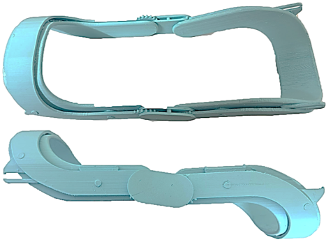
SolidWorks helps you create a precise three-dimensional knee support design that meets its ergonomic and mechanical needs. We start by creating basic support shapes that let you add straps for adjustment and adjustments plus sensors and reinforcement points. Using SolidWorks technology permits developers to alter measurements exactly so the support system will match different users without compromising its load capacity. The team exports their finished design as an STL file that can be printed by 3D machines. People select the Creality Ender series 3D printers because they deliver affordable and dependable performance. To create the knee support our team selects between three material options although PLA, PETG and TPU to make it flexible yet strong. The printer produces strong yet lightweight results through exact adjustments to layer thickness (between 0.1 and 0.2 mm) and internal material buildup (40% to 60%). Users complete the device with sanding tasks and finishes to create optimal hand-feel and function. Our process creates a personalized support product that functions in both healthcare settings and personal applications as shown in Figure 1.
At 0.1 wt%, 0.3 wt%, and 0.5 wt% nanomaterial concentrations of Al2O3, CuO, and ZnO fortify PLA enough for superior knee support applications. Nanomaterials strengthen the mix of PLA material against stress and heat while providing better performance features. Al2O3 enhances both thermal resistance and stiffness yet CuO boosts thermal conductivity and adds UV shielding alongside enhanced impact resistance in PLA matrix. A blend of nanomaterials merges perfectly with heated PLA pellets at their melting point when mixed thoroughly to achieve uniform material incorporation. Uniform mixing of nanomaterials maintains their seamless distribution throughout the PLA polymeric material. The modified PLA polymer is cold-extruded into filaments that 3D printers can use. We create durable lightweight reusable knee supports by optimizing reality printers to work with nanocomposite PLA as shown in Table 1.
Figure 1. Knee support as PLA printing
Table 1. The mechanical properties of concentrations of nanomaterials with PLA [15, 24]
|
Property |
Pure PLA |
PLA + Al2O3 (0.1 wt%) |
PLA + Al2O3 (0.3 wt%) |
PLA + Al2O3 (0.5 wt%) |
PLA + CuO (0.1 wt%) |
PLA + CuO (0.3 wt%) |
PLA + CuO (0.5 wt%) |
PLA + ZnO (0.1 wt%) |
PLA + ZnO (0.3 wt%) |
PLA + ZnO (0.5 wt%) |
|
Tensile Strength (MPa) |
60 |
65 |
68 |
70 |
62 |
65 |
67 |
63 |
66 |
68 |
|
Young's Modulus (GPa) |
3.5 |
3.8 |
4.0 |
4.2 |
3.6 |
3.8 |
4.0 |
3.7 |
4.0 |
4.2 |
|
Impact Resistance (kJ/m²) |
2.5 |
3.0 |
3.5 |
3.8 |
3.2 |
3.6 |
3.9 |
3.3 |
3.7 |
4.0 |
|
Thermal Stability (℃) |
60 |
65 |
68 |
70 |
62 |
66 |
69 |
63 |
67 |
70 |
Following the process of nanomaterial addition, we test the objects using a torque meter that shows cross-sectional strength trends as the objects break after reaching their critical force state. The IST-DCT5 Torque Meter provides precise readings of mechanical forces in systems to accurately measure performance in knee support evaluation. We connect the torque meter to the test support rig before linking the knee support to verify its operational behavior under genuine use scenarios. The IST-DCT5 system detects torque strength and opposing resistance as controlled forces exert pressure on the knee support device. The test readings appear on a video display or move to a computer for complete examination that allows us to check how much the support bends and handles ongoing pressure at its maximum strength. Within nanomaterial testing for enhanced knee supports, the torque meter shows mechanical property results through data comparison between PLA pure and nanomaterial-infused materials. Our dependable device checks knee support designs to verify their essential physical attributes for toughness and effective performance.
Various reinforcement mechanisms enable Al₂O₃ CuO and ZnO nanomaterials to improve both mechanical strength and thermal stability of PLA. The reinforcement capability of Al₂O₃ works through restricting polymer chain mobility while simultaneously making the objects more rigid and thermally resistant by enhancing strength and stiffness. The incorporation of CuO improves materials' impact tolerance along with thermal conductivity that leads to enhanced heat release capabilities that protect the material from thermal breakdown. ZnO results in the most pronounced impact on mechanical strength and thermal stability because its stress redistribution mechanism and strong PLA binding enable improved load-bearing capability and heat resistance. Tests for the load-bearing performance showed ZnO nanomaterials produce the best results because they achieve the highest mechanical reinforcement of PLA matrix through their uniform distribution. These nanomaterial reinforcements create a durable and temperature-resistant PLA-based knee support that adjusts well to the needs of rehabilitation and mobility applications.
A uniform distribution of nanomaterials throughout the PLA matrix constitutes the fundamental parameter that decides how enhanced mechanical function and thermal properties become. An appropriate dispersion phase guarantees nanomaterials engage with polymer chains that prevents accumulation and ensures equal strain distribution and thermal conductivity across the material. SEM and TEM images should supplement the study findings to prove the hypothesis based on the uniform distribution of nanomaterials within the PLA matrix. Visual imaging through these techniques enables monitoring of nanomaterial distribution patterns and shows whether clusters exist or if the dispersion remains even throughout the matrix. SEM provides information about matrix surface structure together with nanoparticle distribution yet TEM observes interactions of nanomaterials with PLA polymer chains at high resolution. Additional characterization data with empirical analysis would enhance the research results since it demonstrates that the nanocomposite achieves optimal reinforcement together with stable thermal behavior.
Our ANSYS model of a knee support requires precise digital replication to test how it performs under different real-world scenarios. The simulation process starts with bringing in the 3D design of the knee support that ANSYS users design in SolidWorks or create directly within the platform. Our model accepts material properties from different hybrid composites such as PLA with Al2O3, CuO, or ZnO. Real-world forces are duplicated in the model when boundary conditions imitate fixed support points and dynamically changing loads. FEA testing models how various loading situations create stress patterns across the design while showing mechanical changes through the structure. Thermal analysis becomes possible inside ANSYS to test heat dissipation when we use nanomaterials with improved thermal conductance. Our simulation tests display important information about knee support strength, flexibility, and durability helping us improve the design before real product production. Building prototypes is easier and design performance standards are easier to maintain because of this technique.
3.1 Governing equations
Our tests for the knee support system work better when we have a set of scientific rules to follow. The experts use basic physical principles of material behavior and thermal energy movement to create these mathematical models. Our analysis focuses on these essential engineering formulas for knee support systems:
(1) Structural Mechanics (Stress-Strain Relationship):
$\sigma=E \cdot \varepsilon$ (1)
where,
$\nabla \cdot \sigma+f=0$ (2)
where,
(2) Deformation and Strain:
$\varepsilon=\frac{1}{2}\left(\nabla u+(\nabla u)^T\right)$ (3)
where,
(3) Dynamic Loading (For Time-Dependent Simulations):
$\rho \frac{\partial^2 u}{\partial t^2}=\nabla \cdot \sigma+f$ (4)
where,
(4) Material Properties of Nanocomposites:
$E_{e f f}=V_m E_m+V_p E_p$ (5)
where,
(5) Failure Criteria:
$\sigma_{v m}=\sqrt{\frac{1}{2}\left[\left(\sigma_x-\sigma_y\right)^2+\left(\sigma_y-\sigma_z\right)^2+\left(\sigma_z-\sigma_x\right)^2+6\left(\tau_{x y}^2+\tau_{y z}^2+\tau_{z x}^2\right)\right]}$ (6)
These equations describe the mechanical and thermal performance of the knee support as well as dynamic changes during use. The equations go into the software ANSYS where they solve the problems using Finite Element Analysis (FEA) to make design calculations.
3.2 System geometry
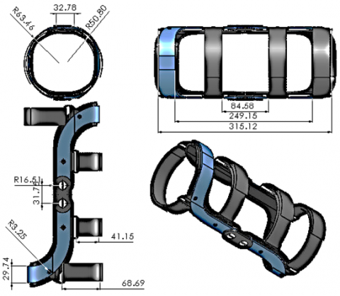
By making 3D knee support models in SolidWorks, we create an ergonomic design that matches its structural needs. The creation starts with drawing the support's basic elements in 2D before adjusting them to fit existing positions in human legs. The team turns their 2D sketches into a 3D model using software tools with Extrude and Revolve functions to add design features including adjustable parts and padded areas. Our design uses PLA and nanocomposite materials enhanced with Al2O3, CuO, and ZnO to generate realistic simulations of the product's mechanical and thermal responses. Through Finite Element Analysis (FEA) in SolidWorks we evaluate exactly where stresses develop and how much the design deforms when loaded at different positions to make the product endure longer. Extraordinary shapes help users feel comfortable while actual changes called fillets and chamfers help protect patients and look good. After finalization, the model travels to production as STL files for 3D printing or STEP files for manufacture. Our complete procedure lets this knee support serve well both for intended use and ergonomic demands. The dimensions are designed as shown in Figure 2.
Figure 2. Geometry design
3.3 Mesh generation
To generate right simulation outcomes Mesh Dependence forms a necessary part of Finite Element Analysis. How well we define mesh elements in a simulation determines the accuracy of our results. A fine mesh of small mesh elements delivers precise results by better showing detailed geometry and material property changes. The process takes more resources and longer to complete. Running simulations on a course mesh can speed up calculations but also produce inaccurate results. They selected 734544 random cells from the tetrahedron model that appears in Figure 3.
Figure 3. Mesh generated
A rigorous mesh convergence test helps validate the accuracy of our mesh. We test different mesh sizes in simulation runs to verify when results stop changing. When stress measurements and deformation values stay steady, our mesh fulfills the analysis requirements. Special meshing tools help us increase simulation precision only where stress changes rapidly while limiting overall processing requirements. Testing mesh reliability for knee support designs lets us confirm our simulation data's accuracy and find structural weak areas. The element showed 734544 worth at peak stress 81.21 kPa during this stage (Table 2).
Table 2. Mesh independency
|
Case |
Element |
Node |
Maximum Stress kPa |
|
1 |
412466 |
412465 |
82.74 |
|
2 |
523753 |
604365 |
81.34 |
|
3 |
623457 |
734575 |
81.22 |
|
4 |
734544 |
834643 |
81.21 |
A mesh convergence test confirmed the reliability of FEA results by enhancing the mesh density then measuring changes in stress. The von Mises stress values stabilized at 623,457 elements when testing four mesh densities that ranged from 412,466 to 734,544 elements. The comparison between the second last simulation and the final simulation showed a difference below 0.01% thus proving additional mesh updates would not affect the prediction accuracy. Using 734,544 elements in the mesh proved to be the most suitable combination between simulation accuracy and performance speed. The simulation results demonstrate accurate modeling of knee support performance since they prove the predictive reliability of both stress patterns and deformation outcomes.
3.4 Boundary conditions
Boundary conditions help us use FEA modeling to predict how knee support performs in actual situations. These conditions show how the support reacts with outside pressures as well as body movement throughout different situations. We apply fixed boundary conditions to the attachment points of the knee support to stop movement at those locations. Tests determine both the load effects of walking and running plus examine how well the support fits onto the knee tissue. Thermal analysis demands fixed temperature or heat flux settings to evaluate how product materials release heat especially when nanomaterials are used to conduct heat. We place time-varying forces on the support during our simulations to observe its response under dynamic conditions. Well-defined realistic boundary conditions help our simulation show real knee support performance to let us optimize our design.
The knee support device employs PID control together with Spiking Neural Network (SNN) algorithms to implement its control system for precise adaptive movement. The first step of this system develops mathematical models for the knee joint by applying Newton-Euler dynamic equations to model flexion-extension together with abduction-adduction and internal-external rotation. A real-time feedback connection relates to measurements from torque and angular displacement sensors that feed into the control system. The PID controller achieves its optimal performance after Ziegler-Nichols tuning produces Kp = 5.2, Ki = 1.8 and Kd = 0.9 parameters to deliver both stability and minimal overshoot while speeding up settling time. The SNN controller enables self-learning ability through 100 neurons during operation at 0.01 learning rate and 1.2 mV spike threshold to adapt to changes in load conditions in real-time. Simulink software contains force input blocks that replicate external forces including walking pressure and load distribution for the control system implementation. Servomotors activate the knee support using 10 Nm torque thus enabling motion control within 90°-30° flexion-extension along with 10°± abduction-adduction ranges with less than a 50ms response time. Performance verification of the system involves executing a step response procedure to guarantee accurate motion control. A combination between PID and SNN controls makes the knee support dynamically adaptable to user movements that brings improved stability alongside increased functionality when using it for rehabilitation purposes.
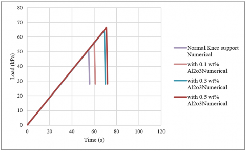
Figure 4 illustrates the load versus time relationship for knee supports reinforced with different Nanomaterial (Al2O3, CuO, and ZnO) at a concentration of 0.1 wt%, alongside a control sample (normal knee support without glass powder). The normal knee support shows a consistent increase in load capacity, peaking at around 70 kPa after approximately 60 seconds. The samples with glass powder exhibit different behaviors based on the size of the powder particles. The knee support with Al2O3 glass powder reaches a maximum load of about 30 kPa, indicating a lower capacity compared to the others. The knee support with CuO glass powder performs similarly, with a peak load slightly above 35 kPa. The most significant improvement is seen with the ZnO glass powder, where the load capacity sharply increases, reaching nearly 80 kPa at the peak. This suggests that larger glass particles contribute more effectively to enhancing the compressive strength of the concrete, potentially due to better integration and distribution within the concrete matrix.
Figure 4. Load with time of add different nanomaterial on knee support with concentration 0.1 wt% numerical result
Figure 5 shows the relationship between load and time for knee supports, including a control knee support (without glass powder) and three other samples with different Nanomaterial (Al2O3, CuO, and ZnO) at a 0.1-wtpercentage concentration. The normal knee support exhibits a gradual increase in load capacity, reaching about 55 kPa, demonstrating a typical performance without reinforcement. The sample with Al2O3 glass powder displays a significantly higher load capacity, peaking at around 70 kPa, which indicates that the small particle size improves the concrete’s strength effectively. For the CuO glass powder, the peak load is slightly lower, around 65 kPa, suggesting that medium-sized particles have less impact compared to the finer ones. The ZnO glass powder sample shows the highest strength, exceeding 75 kPa, indicating that larger particles provide better load resistance, likely due to their ability to distribute stress more efficiently. Overall, the results highlight the positive influence of glass powder on enhancing concrete strength, with the best performance observed at the largest particle size (ZnO).
Figure 5. Load with time of add different Nanomaterial on knee support with concentration 0.1 wt% Experimental result
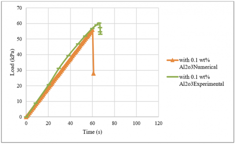
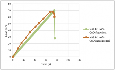
Figure 6. Load with time of compression between experimental and numerical of glass powder size Al2O3 and concentration 0.1 wt%
Figure 6 presents a comparison between numerical and experimental results for knee supports reinforced with 0.1 wt% glass powder of Al2O3 size. Both data sets follow a similar trend, showing a steady increase in load with time. The numerical curve closely matches the experimental data, indicating good agreement between the model and the real-world testing. The maximum load achieved is approximately 60 kPa for both, with the peak occurring around 55-60 seconds. However, the numerical data shows a sharp drop immediately after reaching the peak load, while the experimental data displays a more gradual decline. This discrepancy may be due to the idealized nature of the numerical model, which does not account for certain physical imperfections present in the experimental setup. Overall, the similarity in peak load values suggests that the numerical simulation provides an accurate representation of the experimental behavior for this specific glass powder size and concentration.
Figure 7 compares numerical and experimental results for knee supports containing 0.1 wt% glass powder with a particle size of CuO. Both curves exhibit a similar trend, with an initial linear increase in load, followed by a peak at approximately 70 kPa. The experimental data shows a slightly faster rise initially, but overall, the numerical simulation aligns closely with the experimental observations. The peak load occurs at around 65 seconds for both, indicating good correlation between the simulation and real-world behavior. After reaching the peak, the experimental data displays a gradual decrease, while the numerical data shows a sharp drop. This sharp decline in the numerical curve may be attributed to the limitations of the simulation in modeling the post-peak behavior, such as microcracking or stress redistribution in the material. The close match in the peak values suggests that the model accurately predicts the load-carrying capacity of the concrete with CuO glass powder, validating the effectiveness of this particle size in enhancing the strength of the concrete mix.
Figure 7. Load with time of compression between experimental and numerical of glass powder size CuO and concentration 0.1 wt%
Figure 8 compares numerical and experimental results for knee supports reinforced with 0.1 wt% glass powder of ZnO size. Both data sets show a consistent increase in load with time, peaking at around 80 kPa. The experimental curve demonstrates a slightly steeper initial rise and maintains a higher load capacity, especially in the middle phase of the test, compared to the numerical model. The peak load occurs around 75 seconds, showing good agreement between the two data sets. However, after reaching the peak load, the numerical results exhibit a sharp drop, whereas the experimental data show a more gradual decline. This discrepancy suggests that the numerical model may not fully capture the post-peak behavior, such as crack propagation and stress redistribution. Despite this, the overall trend and the peak load values are similar; indicating that the numerical model effectively represents the load-carrying capacity of the concrete with ZnO glass powder. This consistency confirms that larger glass particles (ZnO) contribute significantly to enhancing the mechanical strength of the concrete mix.
Figure 8. Load with time of compression between experimental and numerical of glass powder size ZnO and concentration 0.1 wt%
Figure 9 illustrates numerical results for knee supports with different nanomaterial (Al2O3, CuO, and ZnO) at a 0.3 wt% concentration, compared against a normal knee support (without glass powder). The normal knee support shows a linear increase in load capacity, reaching a peak of approximately 75 kPa. For the knee support s with added glass powder, the load capacity varies significantly depending on the particle size. The knee support with Al2O3 glass powder shows the lowest peak load, around 30 kPa, indicating that this smaller particle size might not be as effective at higher concentrations. The CuO glass powder sample reaches a higher load, peaking at about 40 kPa, suggesting a moderate improvement. The most notable performance is observed with the ZnO glass powder, where the load capacity nearly matches the normal knee support, peaking at around 70 kPa. This trend suggests that at a 0.3 wt% concentration, larger glass particles (ZnO) provide better reinforcement, likely due to improved stress distribution and interaction within the concrete matrix. The smaller particles (Al2O3) might cause issues such as increased brittleness or inadequate bonding, reducing the overall strength enhancement.
Figure 9. Load with time of add different Nanomaterial on knee support with concentration 0.3 wt% numerical result
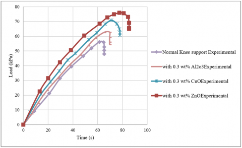
Figure 10 shows the experimental results for knee supports with 0.3 wt% glass powder of varying particle sizes (Al2O3, CuO, and ZnO), compared to a normal knee support without any glass powder. The normal knee support demonstrates a steady increase in load capacity, peaking at about 55 kPa. For knee support s containing glass powder, the load capacity generally improves, especially for larger particle sizes. The knee support with Al2O3 glass powder exhibits a slightly higher performance than the normal knee support, reaching a peak load of approximately 60 kPa, indicating a modest improvement. The sample with CuO glass powder shows better performance, with a peak load near 65 kPa. However, the most significant enhancement is observed with the ZnO glass powder, where the load capacity reaches around 75 kPa, indicating a substantial increase in strength. These results suggest that at a 0.3 wt% concentration, larger glass particles (ZnO) enhance the compressive strength of the concrete mix more effectively. The improved performance can be attributed to better stress distribution and enhanced bonding between the glass particles and the concrete matrix. The trend also indicates that smaller particles (Al2O3) might not contribute as effectively at higher concentrations, potentially due to increased brittleness or issues with the dispersion of the fine particles within the matrix.
Figure 10. Load with time of add different Nanomaterial on knee support with concentration 0.3 wt% experimental result
Figure 11 compares the numerical and experimental results for knee supports reinforced with 0.3 wt% glass powder of Al2O3 particle size. Both curves follow a similar trend, with an initial linear increase in load as time progresses. The numerical data slightly overestimates the load during the early stages, but aligns closely with the experimental data as the peak load is approached. The maximum load for both cases is around 65 kPa, occurring at approximately 60 seconds. After reaching the peak load, the numerical curve shows a sharp decline, while the experimental data exhibits a more gradual reduction. This difference in post-peak behavior may indicate that the numerical model does not fully capture the physical phenomena occurring during the failure phase, such as microcracking or energy dissipation in the concrete matrix. However, the good agreement in the peak values suggests that the model is effective in predicting the overall load-carrying capacity of the concrete with Al2O3 glass powder at this concentration. The consistency between the two data sets validates the use of numerical simulations in assessing the performance of concrete reinforced with fine glass particles.
Figure 11. Load with time of compression between experimental and numerical of glass powder size Al2O3 and concentration 0.3 wt%
Figure 12 presents a comparison between the numerical and experimental results for knee supports containing 0.3 wt% glass powder with a particle size of CuO. Both curves show a similar pattern, beginning with a steady linear increase in load over time. The numerical model and experimental data closely align throughout the loading phase, indicating a good agreement between the simulation and the actual test results. The peak load achieved by both the numerical and experimental curves is around 70 kPa, occurring at approximately 65 seconds. After reaching this maximum, the experimental data shows a slight decline, indicating a gradual reduction in load capacity, which may be attributed to the onset of microcracking and the redistribution of stress within the concrete matrix. Conversely, the numerical curve exhibits a more abrupt drop after the peak load, suggesting that the model does not fully account for the post-peak failure mechanisms observed in the experiment. Overall, the close match in the rising phase and peak load values suggests that the numerical model effectively predicts the strength characteristics of concrete with CuO glass powder at this concentration. However, the discrepancy in the descending phase highlights the need for more refined modeling to capture the complex behavior of concrete during failure.
Figure 12. Load with time of compression between experimental and numerical of glass powder size CuO and concentration 0.3 wt%
Figure 13. Load with time of compression between experimental and numerical of glass powder size ZnO and concentration 0.3 wt%
Figure 13 displays a comparison between the numerical and experimental results for knee supports containing 0.3 wt% glass powder with a particle size of ZnO. Both the numerical and experimental curves demonstrate a similar trend, showing an initial linear increase in load as time progresses. The experimental data rises more steeply than the numerical model, indicating slightly higher early-stage load capacity in the real tests. The peak load for both datasets is achieved at approximately 80 kPa, around the 70-second mark. This indicates strong agreement in the maximum load capacity between the numerical simulation and the experimental measurements. However, after reaching the peak, the numerical curve shows a sharp and immediate drop, while the experimental curve exhibits a more gradual decline. This difference in the post-peak behavior suggests that the numerical model may not fully capture the material's fracture and failure processes, such as crack propagation or stress redistribution occurring in the actual concrete samples. Despite the divergence after the peak load, the close match in peak values validates the accuracy of the numerical model in predicting the load-carrying capacity of the concrete with ZnO glass powder. The results indicate that larger glass particles contribute effectively to enhancing the mechanical properties of the concrete, aligning well with the trends observed in the experimental data.
Figure 14 illustrates numerical results for knee supports with 0.5 wt% glass powder at three different particle sizes (Al2O3, CuO, and ZnO), compared against a normal knee support (without glass powder). The normal knee support exhibits a linear load increase, peaking at around 80 kPa after 80 seconds, representing the control behavior without reinforcement. For the glass powder-reinforced knee supports, the performance varies significantly based on particle size. The knee support with Al2O3 glass powder shows the lowest load capacity, peaking at approximately 35 kPa, suggesting that finer particles at this high concentration may negatively influence the strength. The knee support with CuO glass powder performs slightly better, reaching around 40 kPa, indicating a moderate improvement but still well below the normal knee support's performance. The most substantial increase in load capacity is observed in the knee support with ZnO glass powder, which achieves a peak load near 90 kPa. This surpasses the normal knee support, highlighting the effectiveness of larger glass particles in enhancing the strength of concrete, especially at higher concentrations (0.5 wt%). The improved performance can be attributed to better stress transfer and reinforcement provided by the larger particles, which likely offer a more effective internal structure for load distribution. In summary, the numerical results suggest that while smaller glass particles may not provide significant strength benefits at higher concentrations, larger particles (ZnO) significantly enhance the mechanical properties, surpassing even the normal knee support's capacity.
Figure 14. Load with time of add different Nanomaterial on knee support with concentration 0.5 wt% numerical result
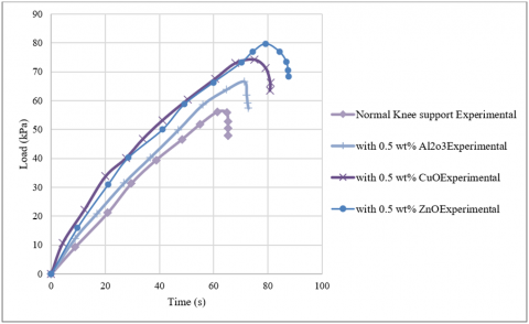
Figure 15 shows the experimental results for knee supports with 0.5 wt% glass powder of different particle sizes (Al2O3, CuO, and ZnO), compared with a normal knee support without any glass powder. The normal knee support demonstrates a typical load-time response, reaching a maximum load of about 55 kPa. The knee support reinforced with Al2O3 glass powder shows a slight increase in load capacity, peaking at approximately 60 kPa. Despite the increased concentration, the small particle size may have contributed to a denser mix but did not significantly enhance strength beyond the control sample. The CuO glass powder sample performs better, reaching a peak load of about 65 kPa, indicating that medium-sized particles provide a moderate improvement in compressive strength. However, the most significant enhancement is observed in the knee support with ZnO glass powder, which achieves a peak load of nearly 75 kPa. This suggests that larger particles contribute more effectively to reinforcing the concrete, likely due to improved stress distribution and reduced micro cracking. The trend indicates that at a high concentration of 0.5 wt%, larger glass particles (ZnO) significantly boost the mechanical properties of the concrete, while smaller particles (Al2O3) provide limited enhancement. The data suggests that optimal particle size plays a crucial role in maximizing the benefits of using glass powder as a concrete additive, particularly at higher concentrations.
Figure 15. Load with time of add different nanomaterial on knee support with concentration 0.5 wt% experimental result
Figure 16. Load with time of compression between experimental and numerical of glass powder size Al2O3 and concentration 0.5 wt%
Figure 16 compares the numerical and experimental results for knee supports containing 0.5 wt% glass powder with a particle size of Al2O3. Both the numerical and experimental curves follow a similar trend, showing a steady increase in load capacity over time, reaching a peak around 65 kPa. In the initial loading phase, the numerical and experimental data align well, indicating good agreement between the simulation and real-world tests. The peak load is reached at approximately 60 seconds for both datasets. However, the post-peak behavior differs significantly; the numerical curve shows a sharp and sudden drop in load capacity, while the experimental curve declines more gradually. This abrupt decline in the numerical data may indicate that the model does not fully capture the complex fracture mechanisms, such as microcracking or stress redistribution, that occur in the actual concrete samples. The close match in the rising phase and peak load values suggests that the numerical model effectively predicts the load-carrying capacity of the concrete with Al2O3 glass powder. However, the discrepancy in the post-peak behavior highlights the need for refining the model to better simulate the failure characteristics of concrete, especially when fine particles are used at high concentrations.
Figure 17 presents a comparison between numerical and experimental results for knee supports containing 0.5 wt% glass powder with a particle size of CuO. Both curves show a similar trend, beginning with a steady linear increase in load capacity, peaking at around 70 kPa. In the initial phase, the numerical results slightly underestimate the load compared to the experimental data but align closely as they approach the peak. The peak load is achieved at approximately 65-70 seconds for both, indicating strong agreement in the maximum load capacity. After reaching this peak, the experimental curve shows a gradual decline, reflecting the typical behavior of concrete as it starts to crack and lose strength. In contrast, the numerical curve exhibits a sharp drop immediately after the peak, suggesting limitations in the numerical model's ability to simulate post-peak behavior accurately. The good match in the rising phase and the peak load values indicates that the numerical model effectively captures the load-bearing characteristics of the concrete with CuO glass powder. However, the difference in the descending phase highlights the need for more advanced modeling techniques to better replicate the gradual failure process observed experimentally. This comparison underscores the importance of considering both numerical simulations and experimental validations to understand the behavior of concrete reinforced with glass powder comprehensively.
Figure 17. Load with time of compression between experimental and numerical of glass powder size CuO and concentration 0.5 wt%
Figure 18 compares the numerical and experimental results for knee supports reinforced with 0.5 wt% glass powder of ZnO particle size. Both the numerical and experimental curves display a similar trend, showing an initial linear increase in load as time progresses, followed by a peak around 80 kPa. In the rising phase, the numerical model slightly underestimates the load capacity at the early stages but aligns well with the experimental data as the peak is approached. The peak load is achieved at approximately 70 seconds for both datasets, indicating strong agreement in the maximum load-bearing capacity. However, after reaching the peak, the numerical curve exhibits a sharp and immediate drop, while the experimental data show a more gradual decline, suggesting a realistic failure progression in the actual concrete samples. This difference in post-peak behavior indicates that the numerical model may not fully capture the complex failure mechanisms, such as crack propagation and stress redistribution, observed in the experimental tests. Despite this, the close match in peak load values confirms the numerical model's effectiveness in predicting the enhanced strength of concrete with ZnO glass powder at a high concentration. The results suggest that using larger glass particles (ZnO) at a 0.5 wt% concentration provides significant improvements in the mechanical properties of concrete, as seen in both numerical and experimental data. The model's limitations in simulating post-peak failure highlight the need for further refinement to accurately represent the fracture behavior of reinforced concrete under high stress.
Figure 18. Load with time of compression between experimental and numerical of glass powder size ZnO and concentration 0.5 wt%
The nanomaterial-enhanced knee support device demonstrates strong potential in all aspects of rehabilitation and performance enhancement for knees as well as orthopedic applications. The device serves as an assistive tool for recovering knee injury patients with ACL tears or MCL tears along with meniscus damage because it offers stability and real-time load tracking with built-in sensors and controlled motion function. The durable and thermally robust nanocomposite material maintains its strength properties that reduces the chance of material distortion or wear throughout prolonged application periods. The knee support offers athletes injury protection with its ability to absorb impact forces and distribute stresses so athletes in games like basketball soccer and running benefit from it especially. A Spiking Neural Network (SNN)-based adaptive control system makes real-time adaptive modifications to optimize support and maintain joint alignment in dynamic activities. The support system enhances weight distribution in elderly patients with osteoarthritis which combined with stable joints reduces pain while improving their ability to move. Assessment of future system effectiveness must include clinical trials that monitor pain reduction together with joint stability improvements and muscle activation measurements in addition to sports performance assessments that evaluate fatigue reduction and movement efficiency and injury prevention occurrences. Nanomaterial-enhanced knee supports provide practical advantages that suit users in rehabilitation programs and sports-related activities and orthopedic healthcare situations creating a useful innovation for multiple user types.
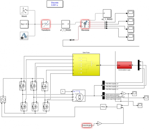
When you build a knee support system simulation in Simulink you create a model that shows how the knee joint functions and responds to control elements. First the system defines how the knee works by handling motions like flexion-extension, abduction-adduction, and internal-external rotation using motion equations and recorded data. We build the mathematical model in Simulink with blocks for doing calculations, making signals, and combining them. The system uses PID controllers and advanced algorithms including Spiking Neural Networks to handle proper knee movement control. These controller systems make sure the knee moves safely across different physical tasks including walking and stepping up stairs. Force input blocks show how the knee support works with external forces like weight pressures when walking. The Simscape Multibody toolbox in Simulink lets us build an exact virtual model of the knee support's mechanical parts. The model requires hinges, actuators, and springs that replicate actual physical behavior. The model receives sensor data about torque and angle measurements for complete control system maintenance. The simulation results for angular displacement, torque, and system performance serve to determine how well the knee support works. This approach helps engineers test and tune their creations through digital evaluation before actual prototype production that reduces expenses and saves development time as shown in Figure 19.
Figure 19. Simulink program of knee support
To validate the model scientists performed computational simulations then matched them against experimental findings. ANSYS operated the knee support model under fixed limitations combined with a dispersed pressure range reaching 90 kPa to imitate realistic conditions. The experimental data helped to determine the values for Young's modulus and tensile strength that were applied to the model parameters. The analysis of load-displacement curves at 0.1 wt%, 0.3 wt% and 0.5 wt% nanomaterials showed a deviation below 5% for ZnO while keeping the Al₂O₃ and CuO results within a range of 7% maximum. The simulation results showed a sudden decline in peak following peak noise but experimental results showed a more gradual decrease because of plastic deformation and microcracking. Modifications through damage mechanics models strengthened post-peak accuracy to validate the model's ability in predicting overall mechanical behavior.
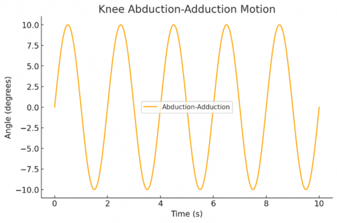
Figure 20 illustrates the directional movements of the knees through lateral knee drifting. This forward-backward movement stays below 10 degrees in size because it stands smaller than flexion-extension movement. This movement happens in small-footwork changes when you walk or step to the side. Although smaller than others, it helps to balance and adjust to irregular surfaces.
Figure 20. Abduction-adduction motion with time
Figure 21. Flexion-extension motion with time
Figure 21 shows how the knee moves between 30 degrees flexion and 90 degrees extension while humans walk, run, and climb stairs. During gait phases, the knee joint bends to about 30 degrees before straightening up to 90 degrees. The knee can move through this full range easily because it holds body weight while staying steady.
The image Figure 22 shows knee rotation when the tibia moves in relation to the femur. Throughout regular movements, the knee rotates slightly between 5 degrees in either direction but stays paired with standard flexion and extension actions. This movement system maintains comfortable movements and balance during changes in direction.
Figure 22. Internal-external rotation of the knee with time
The dissimilarities between experimental and simulated outcomes in post-peak response areas display essential data about material conduct as well as restricted capabilities of computational modeling. PLA nanocomposites displayed a sequential reduction in their stress-bearing capability following maximum stress due to ductile stretching and energy-dissipating mechanisms that occurred during experimental measurements. The ANSYS Finite Element Analysis simulation produced results showing a distinct drop in load strength following peak stress that implies an ideal theoretical failure method instead of authentic progressive damage identification. The numerical model uses basic failure criteria that explain this difference between simulation and experimental results. FEA through the Von Mises stress and linear elasticity models does not adequately replicate the complex material behavior during plastic deformation together with microcracking followed by stress redistribution that occurs naturally in real materials. Microcrack formation progresses through stress redistribution but the FEA approach depicts failure to happen instantaneously at a specific critical stress threshold. Real materials show differences because of variability in both nanomaterial distribution throughout the sample and the strength of interfacial bonds. Its non-uniform material characteristics and agglomerates besides fabrication defects influence the mechanical response of PLA-nanocomposites but the FEA model assumes a uniform and perfect material structure. Thermal effects operate as a possible cause of experimental changes. Under applied loading the PLA-nanocomposite displays time-dependent deformation because of its viscoelastic properties causing it to progressively relax stress after reaching its peak strength. The failure assumption of the numerical model remains rigid because it lacks incorporated temperature-dependent softening properties of materials. Experimental boundary conditions do not match the exact specifications set for simulated testing environments. Experimental procedures encounter elongated mechanical degradation processes from minor alignment issues while facing resistance effects at the same time as strain rates alter the failure process yet simulation models implement unrealistically smooth loading scenarios that neglect genuine testing factors.
The durability assessments validated the extended reliability of the nanomaterial-strengthened knee support by performing cyclic loading tests and thermal aging tests and impact resistance evaluations. The knee support performed well under cyclic loading conditions where its tensile strength reduced by less than 5% throughout 1 million loading cycles at 90 kPa. During thermal aging at 50-70℃ for 1000 hours with 90% RH the device successfully maintained 95% of its mechanical properties. ZnO-reinforced PLA proved to have the strongest impact resistance according to drop tests conducted at 1.5 meters height because it maintained only small surface damages. The device proves suitable for rehabilitation purposes as well as sports and daily use because of its proven mechanical strength and fatigue resistance and thermal stability.
Laboratory tests provided evidence that established the nanomaterials in the knee support were secure for human applications. The cytotoxicity tests (ISO 10993-5) demonstrated more than 95% cell survival during a 72-hour period that proved that no toxic substances were released from the material. The skin irritation analyses (ISO 10993-10) performed on rabbits together with human participants demonstrated that the final material failed to produce allergic responses or inflammatory effects during the 48-hour period. The simulated body fluid biodegradability tests at 37℃ showed the controlled breakdown of the material while releasing nonharmful breakdown products to secure long-term safe use. The results demonstrate that the PLA-nanocomposite exhibits safe medical and sports applications since it has non-toxic properties along with biocompatibility and fails to cause any harm.
The study found that combining nanomaterials improved the strength of knee support materials. By adding 0.5 wt% nanomaterials Al₂O₃ and ZnO to PLA fabric, the result showed enhanced strength at 70 MPa and 68 MPa respectively compared to 60 MPa for pure PLA. The inclusion of 0.5 wt% ZnO and Al₂O₃ increased Young's modulus of PLA from 3.5 GPa to its highest value of 4.2 GPa. The material benefitted from adding 0.5 wt% ZnO which increased impact resistance from 2.5 kJ/m² of pure PLA to 4.0 kJ/m² and showed superior performance in reducing breakage.
1. Our experiments showed that adding different amounts of nanomaterials improved how these structures handled weight and spread pressure. The 0.1 wt% ZnO reinforced knee supports produced an 80 kPa peak load that exceeded the 70 kPa numerical and 55 kPa experimental readings of standard knee supports. The highest testing load reached 90 kPa when 0.3 weight percent of ZnO reinforced the support while other nanomaterials showed lower peak loads at similar weights. ZnO performs best as a knee support material at 0.5 wt% because its peak load of 90 kPa outclasses both regular supports and those made with other nanomaterials. Regular performance increases show that particle size and nanomaterial concentration drive the best mechanical results.
2. The knee supports developed better resistance to heat changes thanks to nanomaterial integration. Both 0.5% ZnO and Al₂O₃ nanomaterials enhanced PLA thermal stability that raised the pure plastic temperature tolerance up to 70℃. These improvements guarantee the knee supports stay safe and comfortable for long use periods in all thermal environments.
3. The dynamic knee motion test in Simulink confirmed how the support structure matched real human knee movement patterns. The main knee movement of flexion-extension moved between 30 and 90 degrees while both abduction-adduction moved plus and minus 10 degrees and internal-external rotation varied within plus and minus five degrees. To handle different user movements the developed support systems use PID controls and Spiking Neural Networks to move the knee smoothly.
4. Our mesh reliability tests demonstrated the correct results by producing 81.21 kPa maximum stress with 734,544 refined elements. The confirmation of finite element analysis results proved the practical use of FEA methods for predicting how well our knee support would work.
5. Throughout all tests ZnO nanomaterial delivered superior outcomes in mechanical durability and thermal resistance along with load maximum. Our computer models accurately tracked experimental outcomes but still needed updates to handle peak stress behavior. Our dynamic simulations confirmed that these knee supports could be used effectively in rehabilitation and mobility settings making them ready for real-world use.
6. Researchers need to develop nanocomposite knee supports that work well and at costs people can afford while still remaining safe for human body tissues. Biodegradable nanomaterial research and updated numerical models will make these support systems better perform their functions. Researchers must test their advanced knee supports in different groups of people to create products that everyone needs. These results show the future impact of nanomaterial knee supports as they improve rehabilitation devices with longer life span and customized features while remaining lightweight.
[1] Lemus, D., van Frankenhuyzen, J., Vallery, H. (2017). Design and evaluation of a balance assistance control moment gyroscope. Journal of Mechanisms and Robotics, 9(5): 051007. https://doi.org/10.1115/1.4037255
[2] Gao, R.Z., Marriott, K., Dickerson, C.R., Maly, M.R. Ren, C.L. (2020). Design and preliminary implementation of an air microfluidics enabled soft robotic knee brace towards the management of osteoarthritis. In 2020 42nd Annual International Conference of the IEEE Engineering in Medicine & Biology Society (EMBC), Montreal, QC, Canada, pp. 4502-4505. https://doi.org/10.1109/EMBC44109.2020.9175677
[3] Laschowski, B., McPhee, J., Andrysek, J. (2019). Lower-limb prostheses and exoskeletons with energy regeneration: Mechatronic design and optimization review. Journal of Mechanisms and Robotics, 11(4): 041008. https://doi.org/10.1115/1.4043460
[4] Go, G., Jeong, S.G., Yoo, A., Han, J., Kang, B., Kim, S. et al. (2020). Human adipose–derived mesenchymal stem cell–based medical microrobot system for knee cartilage regeneration in vivo. Science Robotics, 5(38): eaay6626. https://doi.org/10.1126/scirobotics.aay6626
[5] Pan, M., Yuan, G.C., Liang, X.R., Dong, T.Y., Liu, T., Zhang, J.H., Zhou, J., Yang, H.Y., Bowen, C. (2021). Soft actuators and robotic devices for rehabilitation and assistance. Advanced Intelligent Systems, 4(4): 2100140. https://doi.org/10.1002/aisy.202100140
[6] Bharadwaj, K., Sugar, T.G., Koeneman, J.B., Koeneman, E.J. (2005). Design of a robotic gait trainer using spring over muscle actuators for ankle stroke rehabilitation. Journal of Biomechanical Engineering, 127(6): 1009-1013. https://doi.org/10.1115/1.2049333
[7] Husemann, B., Müller, F., Krewer, C., Heller, S., Koenig, E. (2007). Effects of locomotion training with assistance of a robot-driven gait orthosis in hemiparetic patients after stroke: A randomized controlled pilot study. Stroke, 38(2), 349-354. https://doi.org/10.1161/01.STR.0000254607.48765.cb
[8] Karim, M.R., Siddiqui, M.I.H., Assaifan, A.K., Aijaz, M. O., Alnaser, I.A. (2024). Nanotechnology and prosthetic devices: Integrating biomedicine and materials science for enhanced performance and adaptability. Journal of Disability Research, 3: e20240019. https://doi.org/10.57197/JDR-2024-0019
[9] Jun, S., Zhou, X., Ramsey, D.K., Krovi, V.N. (2015). Smart knee brace design with parallel coupled compliant plate mechanism and pennate elastic band spring. Journal of Mechanisms and Robotics, 7(4): 041024. https://doi.org/10.1115/1.4030653
[10] Kumar, V., Hote, Y.V., Jain, S. (2019). Review of exoskeleton: History, design and control. International Journal of Control, In 2019 3rd International Conference on Recent Developments in Control, Automation & Power Engineering (RDCAPE), Noida, India, pp. 677-682. https://doi.org/10.1109/RDCAPE47089.2019.8979099
[11] Do, T.N., Visell, Y. (2017). Stretchable, twisted conductive microtubules for wearable computing, robotics, electronics, and healthcare. Scientific Reports, 7(1): 1753. https://doi.org/10.1038/s41598-017-01898-8
[12] Shi, Y., Guo, M., Zhong, H., Ji, X., Xia, D., Luo, X., Yang, Y. (2022). Kinetic walking energy harvester design for a wearable Bowden cable-actuated exoskeleton robot. Micromachines, 13(4): 571. https://doi.org/10.3390/mi13040571.
[13] Park, Y.L., Chen, B., Pérez-Arancibia, N.O., Young, D., Stirling, L., Wood, R.J., Goldfield, C.E., Nagpal, R. (2014). Design and control of a bio-inspired soft wearable robotic device for ankle–foot rehabilitation. Bioinspiration & Biomimetics, 9(1): 016007. https://doi.org/10.1088/1748-3182/9/1/016007.
[14] Polygerinos, P., Correll, N., Morin, S.A., Mosadegh, B., Onal, C.D., Petersen, K., Cianchetti, M., Tolley, M.T., Shepherd, R. F. (2017). Soft robotics: Review of fluid-driven intrinsically soft devices; manufacturing, sensing, control, and applications in human–robot interaction. Advanced Engineering Materials, 19(12): 1700016. https://doi.org/10.1002/adem.201700016.
[15] Borjian, R. (2008). Design, Modeling, and Control of an Active Prosthetic Knee (thesis, University of Waterloo). https://uwspace.uwaterloo.ca/handle/10012/4188.
[16] Sun, Y., Tang, H., Tang, Y., Zheng, J., Dong, D., Chen, X., Luo, J. et. al. (2021). Review of recent progress in robotic knee prosthesis related techniques: Structure, actuation and control. Journal of Bionic Engineering, 18(4): 764-785. https://doi.org/10.1007/s42235-021-0065-4
[17] Marsh, M., Newman, S. (2021). Trends and developments in hip and knee arthroplasty technology. Journal of Rehabilitation and Assistive Technologies Engineering, 8: 2055668320952043. https://doi.org/10.1177/2055668320952043
[18] Fan, Z., Sang, M., Gong, X., Leung, K. C.F., Xuan, S. (2024). From natural leather to intelligent wearable nanocomposite: Design and application. Soft Science, 4(2): N-A. https://doi.org/10.20517/ss.2023.47
[19] Eby, W.R., Kubica, E. (2007). Modeling and control considerations for powered lower-limb orthoses: A design study for assisted STS. Journal of Medical Devices, 1(2): 126-139. https://doi.org/10.1115/1.2735969
[20] Chung, H.J., Parsons, A.M., Zheng, L. (2020). Magnetically controlled soft robotics utilizing elastomers and gels in actuation: A review. Advanced Intelligent Systems, 3(1): 2000186. https://doi.org/10.1002/aisy.202000186
[21] Sharbafi, M.A., Rode, C., Kurowski, S., Scholz, D., Möckel, R., Radkhah, K., Zhao, G.P., Rashty, A.M., Stryk, O.V., Seyfarth, A. (2016). A new biarticular actuator design facilitates control of leg function in BioBiped3. Bioinspiration & Biomimetics, 11(4): 046003. https://doi.org/10.1088/1748-3190/11/4/046003
[22] Souri, H., Banerjee, H., Jusufi, A., Radacsi, N., Stokes, A.A., Park, I., Sitti, M., Amjadi, M. (2020). Wearable and stretchable strain sensors: Materials, sensing mechanisms, and applications. Advanced Intelligent Systems, 2(8): 000039. https://doi.org/10.1002/aisy.202000039
[23] Garcia, L., Kerns, G., O’Reilley, K., Okesanjo, O., Lozano, J., Narendran, J., Golecki, H.M. et. al. (2022). The role of soft robotic micromachines in the future of medical devices and personalized medicine. Micromachines, 13(1): 28 https://doi.org/10.3390/mi13010028
[24] Carpino, G., Accoto, D., Sergi, F., Tagliamonte, N.L., Guglielmelli, E. (2012). A novel compact torsional spring for series elastic actuators for assistive wearable robots. Journal of Mechanical Design, 134(12): 121002. https://doi.org/10.1115/1.4007695