Rabia Behloul*![]() | Lakhdar Mazouz
| Lakhdar Mazouz![]() | Mohamed Boudiaf
| Mohamed Boudiaf![]() | Fayssal E. Benmohamed
| Fayssal E. Benmohamed![]()
© 2024 The authors. This article is published by IIETA and is licensed under the CC BY 4.0 license (http://creativecommons.org/licenses/by/4.0/).
OPEN ACCESS
The purpose of this paper is to investigate a wind power system utilizing a doubly fed induction generator (DFIG). In this configuration, the stator is directly connected to the grid, while the rotor is linked to the grid via a back-to-back converter. The primary aim is to develop a decoupled control system for the DFIG to improve power quality. To achieve this goal, we introduce a robust control technique as a means to control the reactive and active power of DFIG. This technique is known as sliding mode control. Furthermore, we propose a model-reference adaptive system estimator based on proportional and integral controllers (PI-MRAS) for sensor-less control of DFIG. This estimator is designed to accurately approximate the rotor resistance. The proposed control strategies enhance the performance of the wind energy conversion system, particularly considering variations in the machine's parameters. Simulation results demonstrate the high performance and robustness of control strategies.
doubly fed induction generator, PI-MRAS estimator, robustness, sensor-less control, sliding mode control
Currently, electric energy stands as one of the most extensively utilized forms of energy, taking a leading role in the renaissance of modern technologies [1, 2]. Its significance lies in its rapid growth as an industry, driven by diverse energy sources like petroleum, natural gas, biomass energy, solar energy, and wind energy. These sources are broadly categorized into two main families: conventional energy sources and renewable energy sources. However, the pressing concerns of fossil fuel depletion, greenhouse gas emissions, pollution, and escalating energy prices are the primary issues that have sparked significant research efforts throughout the world to investigate methods for harnessing renewable energy supplies [3-6].
Among the various applications of renewable-energy generation, wind energy has gained a great deal of attention and emerged as the most promising source of energy. Its renewable nature, well-established infrastructure, abundant availability, and relatively competitive cost contribute to its prominence [7-10]. As a result, wind energy can be distinguished as the optimal choice, playing a key role in promoting power conservation and environmental cleanliness [11].
Currently, DFIGs are widely considered for wind power generation. There are a number of advantages that justify the use of DFIGs, including their flexibility to operate at variable speed and constant frequency, size, cost, efficiency, and wide operating range (hypersynchronous and hyposynchronous) in their four quadrants [12-14].
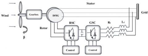
Figure 1. Configuration of WECS-DFIG
The main topology of wind energy generation system is illustrated in Figure 1. In this structure, the rotor is linked to the grid by means of a back-to-back converter, while the stator is directly connected to the grid, sharing the DC bus [15, 16]. The back-to-back converter comprises two key components: the grid-side converter (GSC) and the rotor-side converter (RSC) [17-19]. The RSC is crucial for supplying magnetizing current to the rotor windings, enabling control over the stator’s reactive and active power. Additionally, the RSC is responsible for regulating the stator's active power to extract maximum energy from the wind and improve the quality of power by filtering harmonic currents. It also aids in achieving smooth synchronization with the grid. On the other hand, GSC's main role is to ensure that the DC bus voltage remains unchanged [19-21].
Numerous studies in the literature have focused on controlling DFIG-based wind turbines. The dominant approach employed is field-oriented control (direct or indirect) based on proportional-integral controllers (PI) [22]. FOC aims to decouple the two components (d, q) of the rotor currents in order to separately regulate active and reactive powers [23]. However, FOC requires precise machine parameters and stays susceptible to external disturbances and changes in driving parameters.
To address the non-linearity in the DFIG model, various methods involvie non-linear control laws, like sliding mode control (SMC). This method’s major benefits are its high robustness and ease of implementation [24]. In this context, there is a great deal of work on the application of SMC in wind power systems. Martinez et al. [25] described two coordinated control algorithms based on SMC for RSC and GSC. These algorithms are effective under unbalanced and harmonically distorted grid voltage conditions. The control signals depend only on the states of selected switching variables, making the solution robust against system parameter variations. The use of SMC allows for control in the stationary reference frame, enhancing tracking ability. Mousavi et al. [26] examined the existing literature on conventional SMCs and their modifications to address various control design issues for WECS. The parameter’s optimization of sliding mode surface function and the maximization of a low-power wind energy conversion system are achieved by employing particle swarm optimization-based sliding mode control (PSO-SMC) [27]. In the study [28], the SMC method is used to regulate both the rotational speed on the rotor side and the DC bus voltage on the grid side of the WECS. Xiong et al. [29] proposed a fractional order sliding mode control (FOSMC) strategy. The aim is to directly control the active (reactive) power of DFIG, which has never been used to control DFIG before. FOSMC with disturbance is introduced, and the Caputo derivative is used for the design of the sliding mode surface. At the same time, an improved exponential grasping law is used to reduce the flutter phenomenon in the sliding stage and speed up the grasping progress. Zamzoum et al. [30] proposed an advanced adaptive sliding mode controller (ASMC) to effectively manage the power flow of the DFIG-based wind turbine, especially under varying wind speeds. Xiong et al. [31] developed an innovative control approach, utilizing high-order sliding mode for the DPC of DFIG operating in unbalanced grid voltage situations. In the study [32], two types of nonlinear sliding mode controllers are used to regulate the active (reactive) power in DFIG: one is a first-order SMC, while another utilizes a super twisting algorithm. Karboua et al. [33] proposed a hybrid control approach. This approach combines a terminal sliding mode control based on a high-order super twisting algorithm for the speed loop and a sliding mode control with an exponential reaching law for the current loop. However, the efficacy of control depends on knowledge of generator parameters, in particular the rotor resistance, which can vary from its nominal value by as much as 100% due to rotor heating [34]. On the other side, the complicated online calculations have hindered the practical implementation of the SMC. Consequently, resorting to a thermal model or temperature sensor to obtain this information is deemed undesirable. Benbouhenni et al. [35] proposed a super twisting sliding mode control based on an adaptive-network-based fuzzy inference system (STSMC-ANFIS) to enhence direct power control.
Numerous techniques for online rotor resistance estimation have been developed, including signal injection methods [36], observer methods (Kalman filter, Luenberger observer, sliding-mode observer, adaptive observer,etc), and the model reference adaptive system (MRAS) [37, 38]. The MRAS approach is made up of a reference model and an adaptive model with a shared output quantity. Notably, the reference model remains independent of the rotor resistance, while an adaptive mechanism uses the error signal between outputs to continuously adapt the rotor resistance.
In this study, the effectiveness and reliability of the two side converter of the DFIG are improved using the sliding mode control strategy. To achieve sensor-less control, a novel PI-MRAS estimator is proposed. The proposed PI-MRAS estimator employs active power as the output for both the reference and adaptive models, which grants it immunity to machine parameter variations and enhances its robustness against disturbances.
According to its structure, this research paper comprises the following parts: The second section introduces the concept of modeling a double-fed induction generator, converter, and R-L filter. Section three presents the synthesis of SMC in order to control power injected into the grid, while the proposed PI-MRAS is developed in the fourth section. Section five discusses the simulation results obtained using the MATLAB/SIMULINK environment. Lastly, Section 6 provides a conclusion summarizing the findings.
2.1 Dynamic model of DFIG
Recently, DFIG has become the most commonly used in wind turbines. However, its structure is complicated. For this reason, the development of the mathematical model needs to consider some simplifying assumptions, such as the non-saturation of the magnetic circuit; the loss caused by the hysteresis current is negligible; the structure of the whole machine is symmetrical; the constant air gap; and the sinusoidal distribution of the magnetomotive force in the air gap [39].
Due to the complexity of the three-phase plane equations, we turn to the two-phase system. Thus, the transition from a fixed reference point (a, b, c) to another inflection point (d-q) is achieved by the application of the PARK transformation. As a result, the mathematical model of DFIG is as follows [40, 41]:
-Rotor and stator voltages
$V_{d s}=R_s \cdot I_{d s}+\frac{d \emptyset_{d s}}{d t}-\omega_s \cdot \emptyset_{q s}$ (1)
$V_{q s}=R_s \cdot I_{q s}+\frac{d \emptyset_{q s}}{d t}+\omega_s \cdot \emptyset_{d s}$ (2)
$V_{d r}=R_r . I_{d r}+\frac{d \emptyset_{d r}}{d t}-\omega_r . \emptyset_{q r}$ (3)
$V_{q r}=R_r . I_{q r}+\frac{d \emptyset_{q r}}{d t}+\omega_r \emptyset_{d r}$ (4)
$\omega_r=\omega_s-p . \Omega$ (5)
-Rotor and stator flux
$\emptyset_{d s}=L_s \cdot I_{d s}+M \cdot I_{d r}$ (6)
$\emptyset_{q s}=L_s \cdot I_{q s}+M \cdot I_{q r}$ (7)
$\emptyset_{d r}=L_r \cdot I_{d r}+M \cdot I_{d s}$ (8)
$\emptyset_{q r}=L_r . I_{a r}+M \cdot I_{q s}$ (9)
-Electromagnetic torque
$T_{e m}=p \cdot\left(\emptyset_{d s} \cdot I_{q s}-\emptyset_{q s} \cdot I_{d s}\right)$ (10)
-Active and reactive stator power
$P_s=V_{d s} \cdot I_{d s}+V_{q s} \cdot I_{q s}$ (11)
$Q_s=V_{q s} \cdot I_{d s}-V_{d s} \cdot I_{q s}$ (12)
where, $\left(V_{d s}, V_{q s}, V_{d r}, V_{q r}\right),\left(I_{d s}, I_{q s}, I_{d r}, I_{q r}\right),\left(\emptyset_{d s}, \emptyset_{q s}, \emptyset_{d r}, \emptyset_{q r}\right)$ are the dq components of stator and rotor voltages, currents, and flux, respectively; ($R_s, R_r$) refer to the stator and rotor resistances; $\left(L_s, L_r, M\right)$ are the stator, rotor and magnetizing inductances; $\omega_s$ represents the synchronous speed; $p$ denotes the number of pole peers.
Additionally, to make it easier to control the generator, we choose a dual-phase reference (d-q) related to the rotating field and the stator flux vector $\overrightarrow{\emptyset_s}$ is aligned on the direct axis’d’, which allows us to write [42]:
$\emptyset_{d s}=\emptyset_s$ (13)
$\emptyset_{q s}=0$ (14)
If we neglect the resistance of the stator windings $R_s$, Eq. (1) and Eq. (2) of the stator voltages reduce to these equations:
$V_{d s}=0$ (15)
$V_{q s}=V_s=\omega_s \cdot \emptyset_s$ (16)
By using Eq. (13), Eq. (14), Eq. (15) and Eq. (16) in Eq. (1), Eq. (2), Eq. (3), Eq. (4), Eq. (6), Eq. (7), Eq. (8) and Eq. (9), one may get a new equation for the rotor voltages (Eq. (17) and Eq. (18)). Additionally, it is possible to create the initial formulae for stator powers in a different way, as illustrated in Eq. (19) and Eq. (20):
$\begin{aligned} V_{d r}=R_r \cdot I_{d r}+ & \left(L_r-\frac{M^2}{L_s}\right) \cdot \frac{d I_{d r}}{d t} -S \cdot \omega_s \cdot\left(L_r-\frac{M^2}{L_s}\right) \cdot I_{q r}\end{aligned}$ (17)
$\begin{aligned} V_{q r}=R_r \cdot I_{q r}+ & \left(L_r-\frac{M^2}{L_s}\right) \cdot \frac{d I_{q r}}{d t} +S \cdot \omega_s \cdot\left(L_r-\frac{M^2}{L_s}\right) \cdot I_{d r}+S \cdot \frac{M \cdot V_s}{L_s}\end{aligned}$ (18)
$P_s=-V_s \cdot \frac{M}{L_s} \cdot I_{q r}$ (19)
$Q_s=\frac{V_s^2}{\omega_s \cdot L_s}-\frac{V_s \cdot M}{L_s} \cdot I_{d r}$ (20)
$T_{e m}=-p \cdot \frac{M}{\omega_s \cdot L_s} \cdot V_s \cdot I_{q r}$ (21)
With: $S$: Slip ratio; $V_s$: Stator voltage; $\emptyset_s$: Stator flux.
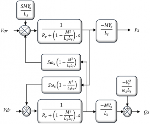
The diagram of simplified DFIG model is illustrated in Figure 2.
Figure 2. Diagram of DFIG model
2.2 Model of converters
The converters can be represented mathematically in the following matrix:
$\left[\begin{array}{l}V_a \\ V_b \\ V_c\end{array}\right]=\frac{V_{d c}}{3} \cdot\left[\begin{array}{ccc}2 & -1 & -1 \\ -1 & 2 & -1 \\ -1 & -1 & 2\end{array}\right] \cdot\left[\begin{array}{l}S_a \\ S_b \\ S_c\end{array}\right]$ (22)
The converter provides straightforward voltages derived directly from the states of control quantities $S_a, S_b$ and $S_c$, representing the control signals. The pulse width modulation (PWM) control strategy determines the state of these quantities.
Since the power configuration remains consistent for both inverter and rectifier operations, the mathematical model remains applicable to both modes.
2.3 Model of R-L filter
The coils making up the filter impose the current flowing between the grid and the filter. The filter voltage in the $d q$ frame is given by the study [43]:
$V_{d f}=R_f \cdot I_{d f}+L_f \cdot \frac{d I_{d f}}{d t}-L_f \omega_s I_{q f}+V_{d g}$ (23)
$V_{q f}=R_f \cdot I_{q f}+L_f \cdot \frac{d I_{q f}}{d t}+L_f \omega_s I_{d f}+V_{q g}$ (24)
where, $V_{d f}, V_{q f}, V_{d g}$ and $V_{q g}$ present the voltages of the filter and the grid respectively; $I_{d f}$ and $I_{q f}$ are the filter currents; $R_f$ and $L_f$ are the filter resistance and inductance respectively.
The SMC approach is a nonlinear control method; this technique demonstrates exceptional robustness, effectively dealing with uncertainties, external disturbances, and exhibiting a rapid response [24].
The purpose of implementing this control rule is to confine the paths of the system's states, ensuring they reach and consistently maintain the sliding surface, even when uncertainties are present [44]. The design primarily involves the determination of three key steps [32]:
1) Choice of sliding surface
The below equation represents a non-linear system:
$\dot{X}=v(X, t)+w(X, t) * z(X, t) ; X \in R^n, \quad z \in R$ (25)
$v, w$: Continuous nonlinear functions.
The sliding surface can be calculated using the general equation below proposed by J.J. Slotine [4, 32, 45]:
$S(X)=\left(\frac{d}{d t}+\delta\right)^{m-1} \cdot e(X)$ (26)
$m$: The system order; $e(X)=X_r-X$: The difference between the reference variable and the state one; $\delta$: positive constant.
2) Convergence condition
Based on the Lyapunov equation, we can define the convergence condition [24, 32, 45, 46]:
$S(X).S\dot{X} <0$ (27)
3) Control law
The sliding mode control is composed of two terms: an equivalent control that describes the system’s behavior on the sliding surface, and a discontinuous control depending on the sign of the sliding surface (named also switching control) [46-48]. The following relationship defines the control law:
$u=u^{e q}+u^n$ (28)
3.1 Rotor side converter
In this section, we focus on power control; $n=0$, the surface becomes the error $e$, so the sliding surfaces are defined by:
$S(P)=P_{s_{-} r e f}-P_S$ (29)
$S(Q)=Q_{s_{-} r e f}-Q_s$ (30)
Based on Eq. (19), Eq. (20), Eq. (29) and Eq. (30), the derivative of the sliding surface gives us:
$\dot{S(P)}=\dot{P_{s_{-} r e f}}+V_s \cdot \frac{M}{L_s} \cdot I_{q r}^{\cdot}$ (31)
$\dot{S(Q)}=\dot{Q_{s_{-} r e f}}-\frac{V_s \cdot M}{L_s} \cdot I_{d r}^{\cdot}$ (32)
From Eq. (17), Eq. (18), Eq. (31) and Eq. (32), and neglecting the coupling terms, and replacing $V_{q r}$ by $V_{q r}^{e q}+V_{q r}^n$ and $V_{d r}$ by $V_{d r}^{e q}+V_{d r}^n$, we get:
$\dot{S(P)}=\dot{P_{s_{-} r e f}} \cdot V_s \cdot \frac{M}{L_s} \cdot\left(\left(V_{q r}^{e q}+V_{q r}^n\right)-R_r I_{q r}\right)$ (33)
$\dot{S(Q)}=\dot{Q_{s_{-} r e f}}-\frac{V_s \cdot M}{L_s} \cdot\left(\left(V_{d r}^{e q}+V_{d r}^n\right)-R_r I_{d r}\right)$ (34)
In a steady state, we have: $(P, Q)=0, S(\dot{P}, Q)=0$.
Consequently, $V_{q r}^{e q}$ and $V_{d r}^{e q}$ are defined by the relations following:
$V_{q r}^{e q}=-P_{s_{-} r e f}^{\cdot} \cdot\left(L_r-\frac{M^2}{L_s}\right) \frac{L_s}{M V_s}+R_r I_{q r}$ (35)
$V_{d r}^{e q}=-Q_{s_{-} r e f}^{\cdot} \cdot\left(L_r-\frac{M^2}{L_s}\right) \frac{L_s}{M V_s}+R_r I_{d r}$ (36)
The switching terms are given by:
$V_{q r}^n=K_P \operatorname{sing}(S(P))$ (37)
$V_{d r}^n=K_Q \operatorname{sing}(S(Q))$ (38)
where, $K_P$ and $K_Q$ constant parameters.
3.2 Grid side converter
The aim of GSC is to maintain a constant voltage on the DC link and to adjust the power factor at the grid connection point. To ensure proper system operation, the intermediate circuit voltage must be constant. The control law that guarantees this is derived from the expressions for active powers and the current flowing through the filter [49].
The following equation expresses the current flowing in the capacitor:
$I_{c a p}=C \cdot \frac{d V_{d c}}{d t}$ (39)
The currents in the capacitor, inverter, and rectifier are linked by the following relationship:
$I_{\text {cap }}=I_{\text {rec }}-I_{\text {inv }}$ (40)
Which allows us to write:
$P_{ {cap }}=P_{{rec }}-P_{i n v}$ (41)
where, $P_{c a p}, P_{r e c}$ and $P_{i n v}$ are the active power in the capacitor, the rectifier and the inverter respectively.
Eq. (41) allows us to calculate the DC voltage $V_{d c}$ and then regulate it using a PI controller by imposing a reference voltage $V_{d c \_r e f}$.
The second objective is to regulate the filter current. The current errors are given by:
$S\left(I_{d f}\right)=I_{d f_{-} r e f}-I_{d f}$ (42)
$S\left(I_{q f}\right)=I_{q f_{-} r e f}-I_{q f}$ (43)
From Eq. (23), Eq. (24), Eq. (42) and Eq. (43), we get:
$\begin{gathered}S\left(\dot{I}_{d f}\right)=I_{\dot{d f_{-} r e f}}-\frac{1}{L_f} \cdot\left(V_{d f}-R_f \cdot I_{d f}+L_f \omega_s I_{q f}\right. -V)\end{gathered}$ (44)
$S\left(\dot{I}_{q f}\right)=I_\dot{q f_{-} r e f}-\frac{1}{L_f} \cdot\left(V_{q f}-R_f \cdot I_{q f}-L_f \omega_s I_{d f}\right)$ (45)
In order to ensure the condition: $S(X) \cdot S\dot{\text(X)}<0$, the control law is formulated as:
$\begin{array}{r}V_{d f}=R_f \cdot I_{d f}+L_f \cdot \frac{d I_{d f}}{d t}-L_f \omega_s I_{q f}+V+K_{I d f} \operatorname{sing}\left(S\left(I_{d f}\right)\right)\end{array}$ (46)
$\begin{aligned} V_{q f}=R_f \cdot I_{q f}+L_f & \frac{d I_{q f}}{d t}+L_f \omega_s I_{d f} +K_{I q f} \operatorname{sing}\left(S\left(I_{q f}\right)\right)\end{aligned}$ (47)
where, $K_{I d f}$ and $K_{I q f}$ constant parameters.
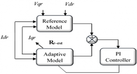
The model reference adaptive system method is a versatile approach that can be employed for the calculation of nearly any parameter or variable of the generator. In this study, the focus is on utilizing this method to estimate the rotor resistor $R_r$. The proposed control method, referred to as the PI-MRAS estimator, encompasses a reference model, an adaptive model, and a PI adaptation mechanism, as depicted in Figure 3. Importantly, the reference model is independent of the computed resistor value. $R_r$ is estimated by evaluating the error derived from the outputs of these two models. Additionally, the output variable of the PI controller is simultaneously employed in the adaptive model through a closed loop [50-52].
Figure 3. Configuration of the PI-MRAS estimator
The active power of the rotor is expressed as:
$P_r=V_{d r} \cdot I_{d r}+V_{q r} \cdot I_{q r}$ (48)
Based on Eq. (17), Eq. (18) and Eq. (48), given that the derivative terms are equal to zero in steady state, we can write:
$P_{r_{-} e s t}=R_r\left(I_{d r}^2+I_{q r}^2\right)+S \cdot \frac{M V_s}{L_s} I_{q r}$ (49)
Eqs. (48) and (49) present the reference and adaptive models respectively.
The PI-MRAS estimator is specifically designed for sensorless control of DFIG and is capable of estimating the rotor resistance without the need for additional sensors. In this estimator, a PI controller is employed to adjust the estimated rotor resistance based on the error between the measured and predicted active power. The proportional term in the controller ensures that the estimated resistance closely tracks the actual value, while the integral term helps eliminate steady-state errors. Additionally, the MRAS part of the estimator provides the reference model against which the power quantities are compared, facilitating the estimation process.
The choice of the PI-MRAS estimator structure is based on a careful balance between robustness, performance, and simplicity. The PI controller offers robustness and simplicity in implementation and tuning, while the MRAS structure allows for adaptation to varying operating conditions, enhancing the overall performance of the estimator.
In summary, the PI-MRAS estimator is preferred for sensor-less control of DFIG systems due to its robustness, simplicity, and ability to provide accurate rotor resistance estimation across a wide range of operating conditions.
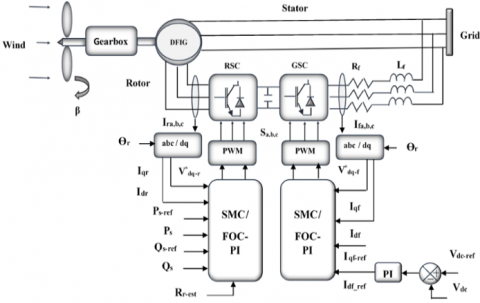
In this section, we employ both conventional and sliding mode control techniques on a 1.5 MW DFIG that is driven by two converters, RSC and GSC. To maintain stability, the DC link voltage is carefully controlled using a PI regulator. Additionally, we apply a PI-MRAS estimator to the proposed control methods to accurately estimate the rotor resistance as illustrated in Figure 4. The model's performance is evaluated through simulation conducted within the MATLAB/SIMULINK environment. Table 1 presents the parameters of the generator.
Figure 4. The overall system control scheme
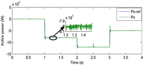
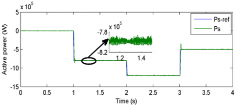
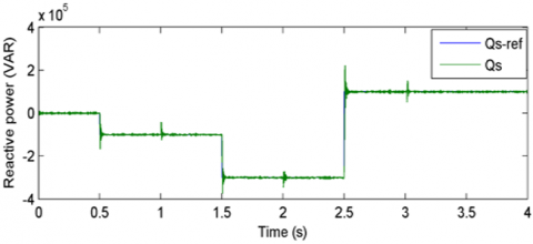
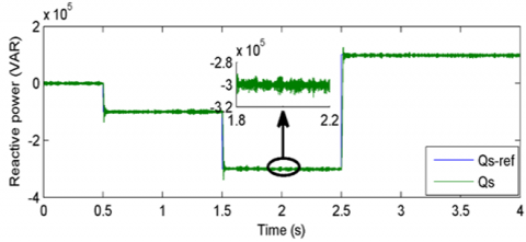
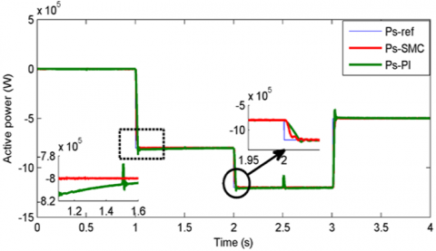
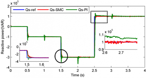
Figures 5 and 6 present, respectively, active and reactive power obtained by using both PI and sliding mode controllers. Different values are imposed to illustrate the behavior of the DFIG. It is clear that the power responses closely track the designated references, exhibiting overshoots at the following time points: t=1, t=2, and t=3 in the case of reactive power when employing the PI controller. Furthermore, it is noted that the variations of the active power have a minor effect on the reactive one, indicating that the decoupling of the two powers is practically achieved during steady-state operation; however, slight fluctuations are noticeable during the transient phase.
Table 1. Generator parameters
|
Parameter |
Value |
Unit |
|
Rotor resistance |
0.03 |
Ω |
|
Stator resistance |
0.02 |
Ω |
|
Rotor inductance |
0.0140 |
H |
|
Stator inductance |
0.0138 |
H |
|
Mutual inductance |
0.0136 |
H |
|
Number of pole pairs |
2 |
/ |
|
Filter resistance |
0.1 |
Ω |
|
Filter inductance |
0.001 |
H |
|
Capacitor C |
0.01 |
F |
(a)
(b)
Figure 5. Active power using: (a) PI Controller (b) SMC
(a)
(b)
Figure 6. Reactive power using: (a) PI Controller (b) SMC
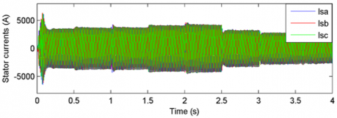
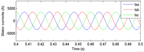
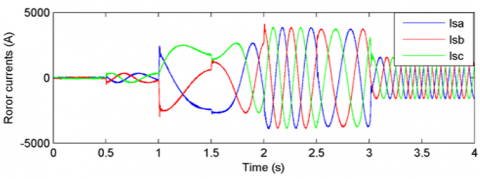
Figures 7 and 8 show the currents in the three-phase reference frame, which have sinusoidal forms in a steady state and are less disturbed. The rotor current frequency settles at 5Hz by the time t=3s, while the stator frequency aligns with the electrical network's frequency, which is 50Hz.
(a)
(b)
Figure 7. (a) Stator currents using SMC (b) Stator currents (zoom)
Figure 8. Rotor currents using SMC
(a)
(b)
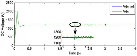
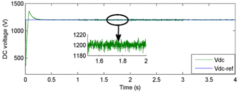
Figure 9. DC bus voltage using: (a) PI controller (b) SMC
From Figure 9, the voltage of the DC bus attains its reference value of 1200 volts at t=0.4s. It is worth highlighting that the FOC method, utilizing PI controllers, exhibits significant overshooting during transient conditions and slight overshooting during a steady-state operation compared to the SMC method.
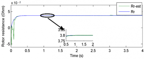
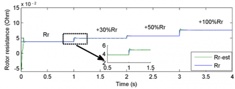
Figure 10 presents the estimated rotor resistance obtained by PI-MRAS and the real one. In Figure 11, the rotor resistance changes with an increase of 30%, 50%, and 100% of its nominal value. From these figures, the estimated resistance follows the real resistance in a short time (t=0.4s) and without error.
Figure 10. Estimated rotor resistance
Figure 11. Variable estimated rotor resistance
Figure 12. Active power (+30% $R_r, L_r$)
Figure 13. Reactive power (+30% $R_r, L_r$)
To evaluate the robustness of the SMC, parameter variations were performed. For this purpose, the values of $R_r$ and $L_r$ are increased by 30% of their nominal values.
As shown in Figures 12 and 13, the active or reactive power reaches its reference value without error, and the overshoot is negligible compared to conventional controllers. Also, note that response times have been improved (25ms when using SMC and 35ms when using PI).
Table 2 shows the system performance and robustness comparison when applying PI and SMC under variable parameters (+30% of the nominal value of $R_r, L_r$).
The response time, overshoot, and steady-state error values indicate that SMC has less overshoot, minimal error in steady state, and higher robustness. Therefore, these results confirm the superiority of SMC over the PI controller.
Table 2. System performance and robustness comparison
|
Controller |
Overshoot (%) |
Error (%) |
Response Time(s) |
Robustness |
|
PI |
0.095 |
0.05 |
0.035 |
Less |
|
SMC |
0.005 |
0.001 |
0.025 |
High |
Both the SMC and the PI-MRAS estimator approaches demonstrate robustness to real-world challenges in WECS. SMC's inherent robustness to disturbances and noise stems from its ability to maintain system trajectory proximity to the desired path despite noisy measurements. This characteristic also extends to its handling of communication delays, as SMC focuses on the system's current state. In contrast, the PI-MRAS estimator's robustness to measurement noise arises from its filtering mechanism, which can mitigate the effects of noise through the integral term of the PI controller and the adaptive nature of the MRAS mechanism. Furthermore, the PI-MRAS estimator can adapt to moderate communication delays by maintaining an internal model of the system's dynamics and adjusting the estimator parameters accordingly. Both approaches also exhibit resilience to modeling errors and parameter variations, with SMC relying on its sliding surface to correct control actions based on the current system state and PI-MRAS adjusting its parameters to account for dynamic variations. Despite the effectiveness of SMC, its implementation complexity is higher than that of PI-MRAS, which combines the familiar PI controller with the MRAS mechanism for relatively simpler implementation in practical wind energy systems.
This research paper presents the application of a nonlinear strategy for enhancing the control of two converters (RSC and GSC) within a WECS-DFIG. The method involves combining sliding mode control with pulse width modulation to achieve precise control. The SMC technique is deployed in both RSC, regulating active and reactive power, and GSC, managing filter current. Additionally, a PI regulator is utilized to maintain the DC voltage at the desired levels.
Another key focus of this study is the estimation of rotor resistance using a PI-MRAS estimator. This estimator demonstrates notable resilience against fluctuations in generator parameters, particularly the rotor resistance. A comparative analysis is performed, comparing the proposed SMC approach with conventional control methods under variations in machine parameters.
Through comprehensive simulation results, it is demonstrated that the proposed control strategies exhibit high performance in terms of reference tracking and robustness. Ultimately, the integration of sliding mode control with the PI-MRAS estimator enhances the performance, effectiveness, and reliability of the wind system.
To summarize, SMC is recognized for its robustness against uncertainties and disturbances, simplicity in design and implementation, and high dynamic performance and accuracy in tracking. However, it suffers from chattering, complexity in variable structure design, and sensitivity to modeling errors. Future directions for SMC include chattering reduction, adaptive designs, and integration with artificial intelligence, such as fuzzy logic or neural networks for enhanced performance.
PI-MRAS offers real-time adaptation of control gains, improved tracking of reference signals, and easy implementation and tuning. Yet, challenges include tuning complexity, model dependency, and convergence issues. Future directions for PI-MRAS involve advanced adaptive algorithms, combination with other control strategies, and integration with predictive control mechanisms.
In conclusion, both SMC and PI-MRAS have unique strengths and limitations, necessitating further research. Future developments aim to enhance adaptive capabilities, integrate with advanced computational methods, and mitigate specific issues like chattering and convergence. These efforts will advance the efficiency, reliability, and adaptability of wind energy conversion systems to meet the dynamic demands of wind power generation.
|
$R_s, R_r$ |
Stator and rotor resistances W |
|
$L_s, L_r, M$ |
Stator, rotor and magnetizing inductances H |
|
$P_s, Q_s$ |
Active and reactive power W, VAR |
|
$d, q$ |
d-q axis |
|
$p$ |
Number of pole peers |
|
DFIG |
Doubly Fed-Induction Generator |
|
WECS |
Wind Eergy Conversion System |
|
SMC |
Sliding Mode Control |
|
MRAS |
Model Rreference Adaptive System |
|
FOC |
Field Oriented Control |
|
RSC |
Rotor Side Converter |
|
GSC |
Gride Side Converter |
|
PI |
Proportional-Integral |
[1] Gasmi, H., Benbouhenni, H., Mendaci, S., Colak, I. (2023). A new scheme of the fractional-order super twisting algorithm for asynchronous generator-based wind turbine. Energy Reports, 9: 6311-6327. https://doi.org/10.1016/j.egyr.2023.05.267
[2] Nguyen, N., Almasabi, S., Mitra, J. (2019). Impact of correlation between wind speed and turbine availability on wind farm reliability. IEEE Transactions on Industry Applications, 55(3): 2392-2400. https://doi.org/10.1109/TIA.2019.2896152
[3] Abolhassani, M.T., Enjeti, P., Toliyat, H. (2008). Integrated doubly fed electric alternator/active filter (IDEA), a viable power quality solution, for wind energy conversion systems. IEEE Transactions on Energy Conversion, 23(2): 642-650. https://doi.org/10.1109/TEC.2007.914181
[4] Majout, B., Bossoufi, B., Bouderbala, M., Masud, M., Al-Amri, J.F., Taoussi, M., El Mahfoud, M., Motahhir, S., Karim, M. (2022). Improvement of PMSG-based wind energy conversion system using developed sliding mode control. Energies, 15(5): 1625. https://doi.org/10.3390/en15051625
[5] Ayadi, M., Naifar, O., Derbel, N. (2019). High-order sliding mode control for variable speed PMSG-wind turbine-based disturbance observer. International Journal of Modelling, Identification and Control, 32(1): 85-92. https://doi.org/10.1504/IJMIC.2019.101958
[6] Aziz, D., Jamal, B., Othmane, Z., Khalid, M., Bossoufi, B. (2019). Implementation and validation of backstepping control for PMSG wind turbine using dSPACE controller board. Energy Reports, 5: 807-821. https://doi.org/10.1016/j.egyr.2019.06.015
[7] Ouammi, A., Dagdougui, H., Sacile, R., Mimet, A. (2010). Monthly and seasonal assessment of wind energy characteristics at four monitored locations in Liguria region (Italy). Renewable and Sustainable Energy Reviews, 14(7): 1959-1968. https://doi.org/10.1016/j.rser.2010.04.015
[8] Islam, M.R., Mekhilef, S., Saidur, R. (2013). Progress and recent trends of wind energy technology. Renewable and Sustainable Energy Reviews, 21: 456-468. https://doi.org/10.1016/j.rser.2013.01.007
[9] Hossain, M.M., Ali, M.H. (2015). Future research directions for the wind turbine generator system. Renewable and Sustainable Energy Reviews, 49: 481-489. https://doi.org/10.1016/j.rser.2015.04.126
[10] Mousa, H.H., Youssef, A.R., Mohamed, E.E. (2020). Optimal power extraction control schemes for five-phase PMSG based wind generation systems. Engineering Science and Technology, an International Journal, 23(1): 144-155. https://doi.org/10.1016/j.jestch.2019.04.004
[11] Mahroug, R., Matallah, M., Abudura, S. (2022). Modeling of wind turbine based on dual DFIG generators. International Journal of Power Electronics and Drive Systems, 13(2): 1170-1185. https://doi.org/10.11591/ijpeds.v13.i2.pp1170-1185
[12] Cardenas, R., Peña, R., Alepuz, S., Asher, G. (2013). Overview of control systems for the operation of DFIGs in wind energy applications. IEEE Transactions on Industrial Electronics, 60(7): 2776-2798. https://doi.org/10.1109/TIE.2013.2243372
[13] Bedoud, K., Ali-Rachedi, M., Bahi, T., Lakel, R. (2015). Robust control of doubly fed induction generator for wind turbine under sub-synchronous operation mode. Energy Procedia, 74: 886-899. https://doi.org/10.1016/j.egypro.2015.07.824
[14] Abo‐Khalil, A.G., Alghamdi, A., Tlili, I., Eltamaly, A.M. (2019). Current controller design for DFIG‐based wind turbines using state feedback control. IET Renewable Power Generation, 13(11): 1938-1948. https://doi.org/10.1049/iet-rpg.2018.6030
[15] Esandi, I., Juankorena, X., Lopez, J., Marroyo, L. (2009). Alternative protection system for wind turbines with doubly fed induction generator. In 2009 International Conference on Power Engineering, Energy and Electrical Drives, Lisbon, Portugal, pp. 501-506. https://doi.org/10.1109/POWERENG.2009.4915226
[16] Desalegn, B., Gebeyehu, D., Tamrat, B. (2022). Wind energy conversion technologies and engineering approaches to enhancing wind power generation: A review. Heliyon, 8(11): 1-21. https://doi.org/10.1016/j.heliyon.2022.e11263
[17] Ghefiri, K., Bouallègue, S., Garrido, I., Garrido, A.J., Haggège, J. (2017). Complementary power control for doubly fed induction generator-based tidal stream turbine generation plants. Energies, 10(7): 862. https://doi.org/10.3390/en10070862
[18] Moumani, Y., Laafou, A.J., Madi, A.A. (2023). A comparative study based on proportional integral and backstepping controllers for doubly fed induction generator used in wind energy conversion system. Archives of Electrical Engineering, 72(1): 211-228. https://doi.org/10.24425/aee.2023.143698
[19] Noussi, K., Abouloifa, A., Katir, H., Lachkar, I., Giri, F. (2021). Nonlinear control of grid-connected wind energy conversion system without mechanical variables measurements. International Journal of Power Electronics and Drive Systems, 12(2): 1141-1151. https://doi.org/10.11591/ijpeds.v12.i2.pp1141-1151
[20] Mirzakhani, A., Ghandehari, R., Davari, S.A. (2021). Performance improvement of DPC in DFIGs during unbalanced grid voltage based on extended power theory. Ain Shams Engineering Journal, 12(2): 1775-1786. https://doi.org/10.1016/j.asej.2020.09.023
[21] Alwash, S.M., Al-Thahab, O.Q.J., Alwash, S.F. (2023). Modeling and control strategies for DFIG in wind turbines: A comparative analysis of SPWM, THIPWM, and SVPWM techniques. Journal Européen des Systèmes Automatisés, 56(6): 963-972. https://doi.org/10.18280/jesa.560607
[22] Aydin, E., Polat, A., Ergene, L.T. (2016). Vector control of DFIG in wind power applications. In 2016 IEEE International Conference on Renewable Energy Research and Applications (ICRERA), Birmingham, UK, pp. 478-483. https://doi.org/10.1109/ICRERA.2016.7884383
[23] Zin, A.A.B.M., HA, M.P., Khairuddin, A.B., Jahanshaloo, L., Shariati, O. (2013). An overview on doubly fed induction generators′ controls and contributions to wind based electricity generation. Renewable and Sustainable Energy Reviews, 27: 692-708. https://doi.org/10.1016/j.rser.2013.07.010
[24] Liu, Y., Wang, Z., Xiong, L., Wang, J., Jiang, X., Bai, G., Li, R., Liu, S. (2018). DFIG wind turbine sliding mode control with exponential reaching law under variable wind speed. International Journal of Electrical Power & Energy Systems, 96: 253-260. https://doi.org/10.1016/j.ijepes.2017.10.018
[25] Martinez, M.I., Tapia, G., Susperregui, A., Camblong, H. (2012). Sliding-mode control for DFIG rotor-and grid-side converters under unbalanced and harmonically distorted grid voltage. IEEE Transactions on Energy Conversion, 27(2): 328-339. https://doi.org/10.1109/TEC.2011.2181996
[26] Mousavi, Y., Bevan, G., Kucukdemiral, I.B., Fekih, A. (2022). Sliding mode control of wind energy conversion systems: Trends and applications. Renewable and Sustainable Energy Reviews, 167: 112734. https://doi.org/10.1016/j.rser.2022.112734
[27] Soufi, Y., Kahla, S., Bechouat, M. (2016). Particle swarm optimization based sliding mode control of variable speed wind energy conversion system. International Journal of Hydrogen Energy, 41(45): 20956-20963. https://doi.org/10.1016/j.ijhydene.2016.05.142
[28] Merabet, A., Ahmed, K.T., Ibrahim, H., Beguenane, R. (2016). Implementation of sliding mode control system for generator and grid sides control of wind energy conversion system. IEEE Transactions on Sustainable Energy, 7(3): 1327-1335. https://doi.org/10.1109/TSTE.2016.2537646
[29] Xiong, L., Wang, J., Mi, X., Khan, M.W. (2017). Fractional order sliding mode based direct power control of grid-connected DFIG. IEEE Transactions on Power Systems, 33(3): 3087-3096. https://doi.org/10.1109/TPWRS.2017.2761815
[30] Zamzoum, O., El Mourabit, Y., Errouha, M., Derouich, A., El Ghzizal, A. (2019). Active and reactive power control of wind turbine based on doubly fed induction generator using adaptive sliding mode approach. International Journal of Advanced Computer Science and Applications, 10(2): 397-406. https://doi.org/10.14569/IJACSA.2019.0100252
[31] Xiong, L., Li, P., Wang, J. (2020). High-order sliding mode control of DFIG under unbalanced grid voltage conditions. International Journal of Electrical Power & Energy Systems, 117: 105608. https://doi.org/10.1016/j.ijepes.2019.105608
[32] Kelkoul, B., Boumediene, A. (2021). Stability analysis and study between classical sliding mode control (SMC) and super twisting algorithm (STA) for doubly fed induction generator (DFIG) under wind turbine. Energy, 214: 118871. https://doi.org/10.1016/j.energy.2020.118871
[33] Karboua, D., Toual, B., Kouzou, A., Douara, B.O., Mebkhouta, T., Bendenidina, A.N. (2023). High-order supper-twisting based terminal sliding mode control applied on three phases permanent synchronous machine. Periodica Polytechnica Electrical Engineering and Computer Science, 67(1): 40-50. https://doi.org/10.3311/PPee.21026
[34] Kenné, G., Fotso, A.S., Lamnabhi-Lagarrigue, F. (2017). A new adaptive control strategy for a class of nonlinear system using RBF neuro-sliding-mode technique: Application to SEIG wind turbine control system. International Journal of Control, 90(4): 855-872. https://doi.org/10.1080/00207179.2016.1213423
[35] Benbouhenni, H., Boudjema, Z., Belaidi, A. (2020). DPC based on ANFIS super-twisting sliding mode algorithm of a doubly-fed induction generator for wind energy system. Journal Européen des Systèmes Automatisés, 53(1): 69-80. https://doi.org/10.18280/jesa.530109
[36] Wang, K., Chen, B., Shen, G., Yao, W., Lee, K., Lu, Z. (2013). Online updating of rotor time constant based on combined voltage and current mode flux observer for speed-sensorless AC drives. IEEE Transactions on Industrial Electronics, 61(9): 4583-4593. https://doi.org/10.1109/TIE.2013.2288227
[37] Kan, J., Zhang, K., Wang, Z. (2015). Indirect vector control with simplified rotor resistance adaptation for induction machines. IET Power Electronics, 8(7): 1284-1294. https://doi.org/10.1049/iet-pel.2014.0422
[38] Kojabadi, H.M. (2009). Active power and MRAS based rotor resistance identification of an IM drive. Simulation Modelling Practice and Theory, 17(2): 376-389. https://doi.org/10.1016/j.simpat.2008.09.014
[39] Lekhchine, S., Bahi, T., Abadlia, I., Layate, Z., Bouzeria, H. (2015). Speed control of doubly fed induction motor. Energy Procedia, 74: 575-586. https://doi.org/10.1016/j.egypro.2015.07.758
[40] Ezzahi, M., Khafallah, M., Majid, F. (2018). Structural integrity of a doubly fed induction generator (DFIG) of a wind power system (WPS). Procedia Structural Integrity, 9: 221-228. https://doi.org/10.1016/j.prostr.2018.06.042
[41] El Ouanjli, N., Motahhir, S., Derouich, A., El Ghzizal, A., Chebabhi, A., Taoussi, M. (2019). Improved DTC strategy of doubly fed induction motor using fuzzy logic controller. Energy Reports, 5: 271-279. https://doi.org/10.1016/j.egyr.2019.02.001
[42] Beniss, M.A., Moussaoui, H.E., Lamhamdi, T., Markhi, H.E. (2021). Improvement of power quality injected into the grid by using a FOSMC-DPC for doubly fed induction generator. International Journal of Intelligent Engineering & Systems, 14(2): 556-5567. https://doi.org/10.22266/ijies2021.0430.50
[43] Li, S., Haskew, T.A., Swatloski, R.P., Gathings, W. (2011). Optimal and direct-current vector control of direct-driven PMSG wind turbines. IEEE Transactions on Power Electronics, 27(5): 2325-2337. https://doi.org/10.1109/TPEL.2011.2174254
[44] Yessef, M., Bossoufi, B., Taoussi, M., Lagrioui, A., Chojaa, H. (2022). Overview of control strategies for wind turbines: ANNC, FLC, SMC, BSC, and PI controllers. Wind Engineering, 46(6): 1820-1837. https://doi.org/10.1177/0309524X221109512
[45] Sellah, M., Abdellah, K., Rezaoui, M.M. (2022). Investigation of SVPWM based sliding mode control application on dual-star induction motor and dual open-end winding induction motor. Periodica Polytechnica Electrical Engineering and Computer Science, 66(1): 80-98. https://doi.org/10.3311/PPee.17910
[46] Benabbas, A., Zaidi, E., Abdessemed, R. (2022). Sliding mode control of a wind power system based on a self-excited asynchronous generator. Journal Européen des Systèmes Automatisés, 55(1): 131-137. https://doi.org/10.18280/jesa.550114
[47] Hostettler, J., Wang, X. (2015). Sliding mode control of a permanent magnet synchronous generator for variable speed wind energy conversion systems. In 2015 American Control Conference (ACC), Chicago, IL, USA, pp. 4982-4987. https://doi.org/10.1109/ACC.2015.7172115
[48] Echiheb, F., Ihedrane, Y., Bossoufi, B., Bouderbala, M., Motahhir, S., Masud, M., Aljahdali, S., ElGhamrasni, M. (2022). Robust sliding-backstepping mode control of a wind system based on the DFIG generator. Scientific Reports, 12(1): 11782. https://doi.org/10.1038/s41598-022-15960-7
[49] Ouassaid, M., Elyaalaoui, K., Cherkaoui, M. (2016). Sliding mode control of induction generator wind turbine connected to the grid. Advances and Applications in Nonlinear Control Systems, Springer, Cham, 531-553. https://doi.org/10.1007/978-3-319-30169-3_23
[50] Karlovský, P., Lettl, J. (2017). Application of MRAS algorithm to replace the speed sensor in induction motor drive system. Procedia Engineering, 192: 421-426. https://doi.org/10.1016/j.proeng.2017.06.073
[51] Korzonek, M., Tarchala, G., Orlowska-Kowalska, T. (2019). A review on MRAS-type speed estimators for reliable and efficient induction motor drives. ISA Transactions, 93: 1-13. https://doi.org/10.1016/j.isatra.2019.03.022
[52] Kumar, R., Das, S., Bhaumik, A. (2019). Speed sensorless model predictive current control of doubly-fed induction machine drive using model reference adaptive system. ISA Transactions, 86: 215-226. https://doi.org/10.1016/j.isatra.2018.10.025