Salah Anis Krim![]() | Fateh Krim*
| Fateh Krim*![]() | Hamza Afghoul
| Hamza Afghoul![]() | Feriel Abdelmalek
| Feriel Abdelmalek![]()
© 2024 The authors. This article is published by IIETA and is licensed under the CC BY 4.0 license (http://creativecommons.org/licenses/by/4.0/).
OPEN ACCESS
Photovoltaic (PV) systems have emerged as a promising energy resource that caters to the future needs of society, owing to their renewable, inexhaustible, and cost-free nature. The output power of these systems relies on solar cell radiation and temperature. In order to mitigate the dependence on atmospheric conditions and optimize power extraction from PV systems, Maximum Power Point Tracking (MPPT) algorithms are employed. To overcome limitations such as steady-state voltage oscillations and improve transient response, presented by the traditionnal Perturb and Observe (P&O) strategy, this paper deals with an improved fuzzy variable step size P&O. The developed MPPT strategy is validated by using Matlab/Simulink™. The obtained results demonstrate the good performance in terms of rapidity and accuracy tracking as well as power loss.
photovoltaic system, matlab/simulink, perturb and observe, MPPT, DC converter
Research and development of alternative energy sources that are renewable, cleaner and have less impact on the environment, have been prompted by the rising demand for energy and the potential for a reduction in the availability of traditional fuels, as evidenced by the petroleum, coal and natural gas crisis [1-3]. Additionally, among the alternative energy sources, the currently thought to be a more practical natural energy source is the generation of electrical energy from PV cells because it is plentiful, available for free, clean and is dispersed throughout the earth. It also plays a crucial role in all other processes of energy production on earth. Therefore, harnessing solar energy through PV cells has gained significant attention in the search for sustainable energy solutions. Besides, it is believed that solar energy incident on the Earth’s surface is 10,000 times larger than global energy consumption, despite the phenomena of sunlight reflection and absorption by the atmosphere [4].
Evaluation of PV source due to its nonlinear output features which change with atmospheric temperature and solar irradiation are another crucial component of using a PV source. The characteristics become more complex, especially when the PV array receives non-uniform insolation, such as in partially shaded conditions, resulting in multiple peaks [5]. Efficiency may reduce due to existence of numerous peaks. Therefore, various methods have been developed to track the maximum power point (MPP), including the P&O algorithm and fuzzy logic controller (FLC), which are commonly used in PV systems.
P&O algorithm can be presented by processing actual values of PV current and voltage, regardless of atmospheric circumstances, type of PV panel or aging, to track the MPP continuously. Due to its easy implementation and simplicity, it has been common method used in the PV system. The method involves perturbing the current or voltage of the PV array, either by decreasing or increasing its value, and comparing the resulting PV output power with the power from the previous perturbation cycle [6]. The control system inclined the PV array operating point in that way if the operating voltage change and the power increase; otherwise, the operating point is moved in opposite direction. The next perturbation cycle of the algorithm is conducted in the same way. The benefits of the P&O method include its simplicity, ease of implementation and control, low cost, and high output power [7, 8].
The FLC has also been widely adopted in PV systems to track the MPP because it is easy to develop, robust and capable of tolerating nonlinearity and working with imperfect inputs without the need for a precise mathematical model [9, 10]. The FLC technique consists of three stages: fuzzification, aggregation and defuzzification. A membership function is created during fuzzification stage to convert the numerical input variables. The input and output system are linguistically related. Rules are the relationships and a fuzzy set is the result of each rule. Therefore, numerous rules are applied to improve the conversion efficiency. A separate output of fuzzy set is created by aggregating the fuzzy sets produced by each rule, which is called as aggregation process. The defuzzification method subsequently sharpens the output from the fuzzy set [11-13].
Driven by the literature survey mentioned earlier, this considers, a modified fuzzy logic controller based P&O for MPPT using a fuzzy variable step size, due to limitations of traditional P&O approach such as delayed convergence or ascent to the MPP, PV power oscillation around the MPP in steady state conditions that results in power loss, and rapid changes in MPP position due to fluctuating atmospheric conditions. The simulation results show the efficiency tracking with solar irradiation change, of the suggested fuzzy step MPPT. This paper is structured as follows. It consists of 5 parts, following introduction, section 2 presents PV system description which consists of PV system, PV panel model and power converter. Besides, section 3 presents the suggested Fuzzy step P&O MPPT, while section 4 consists of the discussion of the simulation outcomes and findings which are obtained from Matlab/Simulink™. Lastly, the conclusion is presented in section 5.
2.1 PV system
Figure 1 illustrates the proposed PV system integrated with a MPPT controller. The system is mainly composed of four parts: the PV array, the boost DC converter, the proposed controller, the load. The PV array converts the solar energy into electrical energy. The boost converter adapts the load impedance to the PV array output for the maximum extraction of PV energy. The controller provides the duty ration D for the DC converter control signal. When designing a PV system, two key aspects need to be considered: the modelling of the MPPT boost DC-DC converter and the modelling of the PV array. The objective is to optimize power transmission by adjusting the load impedance to coincide the operating point with the MPP [14].
Figure 1. Proposed PV system
2.2 PV panel model
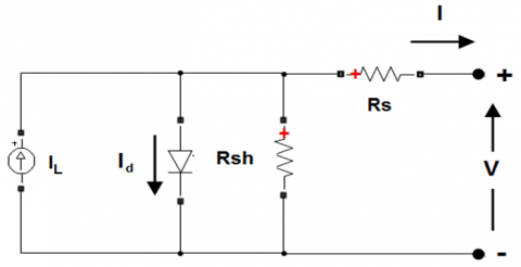
Electrical energy can be generated through the conversion of solar energy, facilitated by solar PV technologies. These technologies rely on solar cells to directly convert sunlight exposure into electrical energy in the form of direct current (DC). Figure 2 illustrates the circuit model of a PV panel, which comprises diodes, resistors, and a current source. PV cells employ a semiconductor structure, typically a p-n junction, to harness the energy from photons in sunlight. When exposed to solar radiation, the cells absorb photons, causing the mobilization of electrons and the subsequent generation of electricity. As a result, when a load is connected to a PV cell during the period of irradiance, electric charges flow as direct current. To achieve the desired current and voltage levels, the cells can be connected in either parallel or series configuration. Connecting the cells in series allows for higher output voltage, while connecting them in parallel enables higher output current.
Figure 2 illustrates the circuit model of the PV array, which enables the determination of $I$ representing the output current of the PV array. Eq. (1) provides the expression of photogenerated current $I_L$ as follows:
$I_L=\left(I_{s c}+k_i\left(T_c-T_{s t c}\right)\right)\left(\frac{G}{G_{s t c}}\right)$ (1)
Figure 2. Model of the PV array
where, $I_{s c}$ is the short circuit current of PV system $(\mathrm{V}=0), k_i$ is the short circuit current coefficient, $T_c$ is the absolute operating temperature, $T_{s t c}$ is the temperature at standard test condition (STC) @ $25^{\circ} \mathrm{C}, G$ is the irradiance and $G_{s t c}$ is the irradiance at standard test condition (STC) @ 1000W $/ \mathrm{m}^2$. But, in indoor condition, the $I_L \approx 0$, where the I-V characteristics are given by Eqs. (2)-(4) as:
$I=I_L-I_o\left(e^{\frac{V-I R_s}{N_s V_t}}-1\right)-I_{s h}$ (2)
$V=\left(I_L-I\right) R_s+n V_t \ln \frac{\left(I_L-I\right)-I_{s h}+I_o}{I_o}$ (3)
$I_{s h}=\frac{V-\left(I_L-I\right) R_S}{R_{s h}}$ (4)
with, $I_o$ is the saturation current, $R_s$ represents the panel series resistance, $R_{s h}$ represents the shunt resistance, $N_s$ is the number of in series cells, $V_t$ is the junction thermal voltage that is given by equation of $V_t=\frac{k T_c}{q}$, where $k$ is the Boltzmann's constant of $1.381 \times 10^{-23} \mathrm{~J} / K$ and $q$ is the elementary charge of $1.602 \times 10^{-19} \mathrm{C}$. The parameters of the PV array under STC are presented in Table 1.
Table 1. Parameters of the solar panel at STC
|
Electrical Characteristics |
Parameters |
|
Rated maximum power (Pmax) |
250.205W |
|
Open-circuit voltage (Voc) |
37.3V |
|
Short-circuit current (Isc) |
8.66A |
|
Voltage at MPP (Vmpp) |
30.7V |
|
Current at MPP (Impp) |
8.15A |
|
Voltage temperature coefficient |
-0.36901%/℃ |
|
Current temperature coefficient |
0.086998 |
where, Pmax corresponds to the power at the MPP, and it mainly depends on the solar irradiance and temperature.
Voc is the PV output voltage for I=0, it decreases for increasing temperature.
Isc it the PV output current for V=0, it increases with the radiance.
Vmpp and Impp correspond to the voltage and current at the MPP, respectively.
The PV voltage Vpv is optimized by the DC converter. The relation between PV voltage and converter output voltage depends on the transistor duty ratio D. The control of the duty ratio, can achieve the required PV voltage. So the function of the controller is to operate PV array at Vmpp accordingly to changes in both solar irradiance and temperature.
2.3 Power converter
Power electronics is essentially employed with PV panels, wind turbines, and geothermal resources which need power conditioning systems, improve grid integration. Energy conversions phenomena occur in order to be usable and user friendly. For example consider PV generator which provides DC power, to obtain AC power here a power electronic converter called inverter is used. A power converter is an power electronic circuit that receives a DC input and generates a DC output with different voltage. This transformation is achieved through high frequency switching actions that involve inductive and capacitive filter elements. The purpose of a power converter is to convert electrical energy from one form to an optimized form that suits the specific load requirements. In the context of PV systems, one commonly used type of power converter is the DC-DC boost converter [15]. Figure 3 illustrates the basic configuration of a DC-DC boost converter. It comprises two semiconductor devices, such as a transistor and a diode/IGBT, as well as an inductor, input and output capacitors, and a DC load connection. The boost converter operates by increasing the input DC voltage, making it a step-up converter, as the output voltage is greater than the source voltage [16].
The equation of the DC-DC boost converter is derived as follows, where the boost level of the output voltage is determined by the duty ratio of the switch and the applied input voltage:
$V_i=V_O(1-a)$ (5)
When the condition of the IGBT/diode is on and D is reverse biased in (6), (7) and (8), the output voltage is obtained from the derivation input voltage and duty ratio as below:
$\frac{d i_L}{d t}=\frac{V_{p v}}{I_L}$ (6)
$\frac{d V_o}{d t}=-\frac{V_o}{R C_{o u t}}$ (7)
$I_{p v}=i_L+C_{i n} \frac{d V_{p v}}{d t}$ (8)
Eqs. (9) and (10) are derived by correlating the relationship between the changing of inductor current with time and PV voltage with inductor when the condition of IGBT/diode turned off and D is forward biased.
$\frac{d i_L}{d t}=\frac{V_{p v}}{L}-\frac{V_o}{L}$ (9)
$\frac{d V_o}{d t}=\frac{i_L}{C_{\text {out }}}-\frac{V_o}{R C_{\text {out }}}$ (10)
By altering the duty cycle $a$, the power converter is in charge of controlling the energy transmission from the input source to the load. Since in steady state the integral of the induction voltage over one time period must be zero, we obtain Eq. (11), and Eq. (12) shows the simplified version of Eq. (11), where PV voltage of cell is represented.
$V_{p v} t_{o n}=\left(V_o-V_{p v}\right) \times t_{o f f}$ (11)
$V_o=\frac{t_{o n}+t_{o f f}}{t_{o f f}} V_{p v}$ (12)
$T=t_{o n}+t_{\text {off }}$ (13)
The general equation of period is stated in (13) where the turn-on time is summed with turn-off time. Then, Eq. (14) represents the ratio of turn on-time to period called as duty cycle, $a$.
$a=\frac{t_{o n}}{T}$ (14)
Then, from Eq. (12), the voltage produced can be derived as (15) where output voltage is determined from the input voltage of solar cell and duty ratio.
$V_o=\frac{1}{1-a} V p v$ (15)
Figure 3. DC-DC boost converter
Traditional P&O operates with a fixed step size. Thus, arises the dilemma between the minimization of PV power oscillation and the optimization of the MPP tracking speed. In fact, a large step size ensures a rapid response, following a step change in solar irradiance, but leads to excessive oscillation, thus causing important power loss. On the contrary, a small step size ensures a reduction in PV power oscillations but reduces the speed of MPP tracking during an abrupt change in solar irradiance. This is why it is necessary to operate with a variable step size to ensure both low power oscillations and high tracking speed. This paper proposes to tune the step size of the P&O using the fuzzy logic to overcome the limitations inherent to the traditional PO with a fixed step.
3.1 Perturb and observe description
P&O techniques are commonly employed to extract the maximum power point in a PV system due to their simplicity and minimal parameters requirement. The voltage of the array is periodically perturbed by either increasing or decreasing it, and the P&O algorithm compares the PV output power with the power from the previous perturbation cycle [17]. If the power increases, the perturbation continues in the same direction; otherwise, it changes direction. As a result, each MPPT cycle induces a change in the terminal voltage of the array. In situations where atmospheric conditions exhibit continuous or gradual changes, the P&O algorithm will subsequently adapt, potentially leading to a loss of PV power [18].
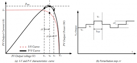
Figure 4. Operation of the P&O MPPT
Figure 4 illustrates the operation of P&O MPPT, taking into account the I-V and P-V characteristics curves and the step size of voltage perturbation. It clearly demonstrates, that under irradiance change, the electrical operating of a PV system is described by the output current and output voltage. The MPP is achieved when the terminal voltage of the PV source is effectively controlled to maintain a value that maximizes the product of PV current and voltage. As shown in Figure 4, the knee point of the standard I-V curve for PV diodes is indicated, with the limits displayed for short circuit current ($I_{S C}$) and open circuit voltage ($V_{o c}$) [19].
The basic concept behind P&O approach for MPPT is to analyze the voltage and output power derivatives of the PV array, which determine the shift in the operating point. This method involves periodically adjusting the PV array voltage by either increasing or decreasing it. If increasing the operating voltage results in a rise of output power, the operation point will be situated at the left of the MPP, needing further voltage perturbation to reach the MPP on the right side. On the other hand, if increasing the voltage leads to a power decrease, the operation point will be located at the right of the MPP, requiring additional perturbation to move towards the left side and approach the MPP [20, 21].
3.2 Fuzzy variable step size perturb and observe description
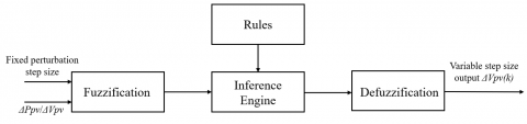
The FLC is a well-known artificial intelligence-based control technique used in MPPT. Fuzzy logic, or fuzzy set theory, is a novel approach to achieve peak power point tracking. In Figure 5, the block diagram of the FLC illustrates the mapping of input variables, such as the first perturbation size and the instantaneous slope of PV power, into linguistic values through fuzzification. This process involves the use of linguistic variables and fuzzy sets, which represent smooth changes in membership rather than abrupt transitions, forming the basis for fuzzy logic controllers [22]. The inference engine in the controller assesses the fuzzy rules and linguistic variable definitions to make decisions and determine the appropriate fuzzy control action. To obtain a non-fuzzy (crisp) control action that closely resembles the fuzzy one, a defuzzification technique is applied since a fuzzy controller produces a fuzzy set as its output. The final step involves obtaining the crisp value for the variable step size, as the output of the controller.
FLC is a heuristic approach that allows the incorporation of human thinking and knowledge into the design of nonlinear controllers [23]. Typically, fuzzy controller rules are expressed using linguistic terms. There are two types of fuzzy inference systems commonly used: Mamdani and Sugeno. The Mamdani inference system synthesizes a collection of linguistic control rules defined by expert human operators, with each rule producing a fuzzy set as its output. This system is particularly suitable for expert system applications, such as medical diagnostics, where the rules are based on human expertise and are relatively straightforward to understand [24]. On the other hand, the Sugeno inference system, also known as the Takagi-Sugeno-Kang inference, uses singleton output membership functions that can be either linear functions or constants of the input values. Unlike the Mamdani system, which computes the centroid of a two-dimensional area, a Sugeno system employs a weighted sum or average of a small number of data points, making it more computationally efficient [25].
Table 2 shows the fuzzy rules table for MPPT. There are about 25 rules developed in the fuzzy logic toolbox to prescribed conclusion of the instantaneous voltage of the variable step size. The inputs indicate the step size perturbation and P-V curve slope while one output indicates variable step size.
Table 2. Fuzzy rules table for MPPT
|
Δe=S(k) E=Voltage Step |
PVS |
PS |
PM |
PH |
PVH |
|
PVS |
PVH |
PVS |
PVS |
PS |
PS |
|
PS |
PVH |
PVS |
PVS |
PS |
PS |
|
PM |
PS |
PS |
PS |
PVH |
PVH |
|
PH |
PS |
PS |
PVH |
PVH |
PVH |
|
PVH |
PVS |
PVS |
PVH |
PVH |
PVH |
where, PVS=Positive Very Small, PS=Positive Small, PM=Positive Medium, PH=Positive High and PVH=Positive Very High.
Figure 5. FLC block diagram
Figure 6. Flowchart of the suggested FLC-based P&O
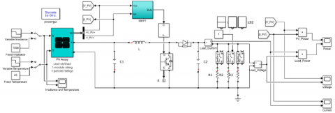
Figure 7. PV system simulation model
Figure 6 illustrates the flowchart of the proposed FLC-based P&O algorithm. This later evaluates power variations and adjusts the operational voltage of a PV system by modifying the effective input resistance of the boost converter through the duty cycle adjustment of the switching device. The system initiates by measuring two parameters: voltage and current from the PV system. The flowchart provides a detailed explanation of the process.
Firstly, the voltage and current measurements lead to two distinct paths: P&O method and FLC. Various calculations are performed based on the measurements to determine the actual power (Ppv (k)), the changes in power (Δ Ppv (k)), and the changes in voltage (Δ Vpv (k)). These calculations involve combining the instantaneous current and voltage values with their respective previous values. The FLC receives two inputs: the slope, which is the result of the division between ΔP and ΔV, and the perturbation step size.
The output of the FLC is the variable step size for making small changes in voltage, which is added to the PV voltage. This action also modifies the duty ratio of the PV voltage on the basis of the two inputs. The PV panel is considered to operate at the MPP condition when the delta power equals zero. When ΔP is greater than zero, the sign is positive, and vice versa. Similarly, when ΔV is positive, the voltage is updated by adding the small changes derived from the output of the FLC. The design of fuzzy logic-based P&O MPPT for PV systems is implemented and simulated in Matlab/Simulink, Figure 7, and is discussed in the following section.
4.1 PV system model
The PV system model then presented using Matlab/Simulink™ software determines system performance based on variable conditions. The model consists of a PV model of 1Soltech 1STH-250-WH, a boost converter, loads and fuzzy logic controller based P&O MPPT algorithm, Figure 7. The PV array with a capacity of 250.205W consists of one series modules and one parallel strings. The loads considered in this model are 5Ω, 30Ω and 100Ω while the power converter used is IGBT with diode boost converter.
4.2 Fuzzy rules
The fuzzy rule is constructed using the fuzzy logic designer in Matlab/Simulink™, as shown in Figure 8. The membership functions involve two input variables and one output variable for the FIS. The first input variable represents the perturbation step size, labeled as FS and depicted in Figure 9. The second input, denoted as S in Figure 10, corresponds to the slope of the P-V curve or ΔP/ΔV. The fuzzy logic controller generates an output called the variable step size (VSS), as illustrated in Figure 11.
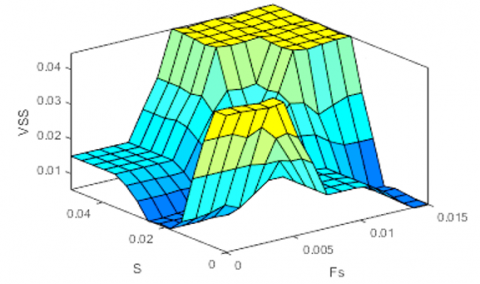
When the design of fuzzy logic is completed, the surface and rules viewers are provided in Figure 12 and Figure 13, respectively. There are 25 different rules corresponding between inputs and output of FIS variables. The example of if-then rule is stated as below:
1. If (A is X1) and (B is Y1) then (C is A1)
……
25. If (A is X5) and (B is Y5) then (C is A25)
where, A=First input, X1=First variable of first input, B=Second input, Y1=First variable of second input, C=Output, A1=First output and A25=25th output.
The fuzzy rule consists of fixed variables A, B, and C, along with changing variables X1, Y1, and A1~A25, which represent the variable relationship according to the fixed variables. These rules are visualized in a 3-D dimension due to the presence of three different FIS variables, as shown in Figure 12.
The FLC has two inputs, namely the fixed step FS and the power slope S. The fuzzification block evalutes these two inputs according to Table 2 rules and then inference is achieved on the basis of the sets of rules. It results the fuzzy sets which is mapped into a crisp variable by using the membership function, Figure 11, to provide by defuzzication the step size of the control signal.
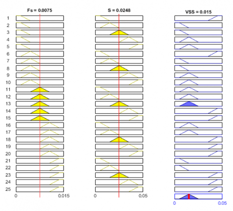
The complete set of rules can be seen in the rule viewer depicted in Figure 13. The inference process of the fuzzy system involves adjusting the two inputs to observe the corresponding output for each fuzzy rule, including the aggregated output fuzzy set and defuzzified output values. The output of the fuzzy logic controller represents the change in duty cycle (ΔD), which completes the P&O algorithm. Therefore, this method is designed in the proposed Fuzzy Logic-based P&O approach to ensure that the PV output always remains in an optimal state.
Figure 8. MPPT controller
Figure 9. Input variable of perturbation step size, FS
Figure 10. Input variable of slope, S
Figure 11. Output variation of variable step size, VSS
Figure 12. 3D of fuzzy rule
Figure 13. Rules viewer
4.3 Boost converter
4.3.1 P-V and I-V curves
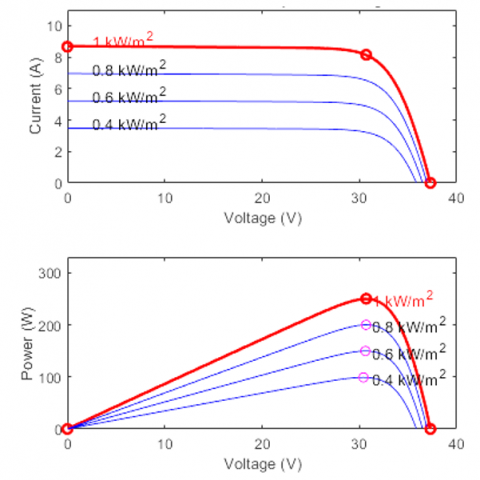
The graphs of Figures 14 and 15 are plotted using the parameters of the 1Soltech 1STH-250-WH array and are displayed for two specific conditions: array @ 25℃ with specified irradiances and array @ 1000 W/m² with specified temperatures. Various irradiance and temperature values are examined to track different states of the maximum power point. In Figure 14, the irradiance levels are varied from 1000W/m² to 400W/m², while in Figure 15, the temperatures range from 85°C to 25℃. These figures show clearly how the maximum PV power, the maximum PV voltage, and the maximum PV current voltage change with solar irradiance and with the temperature. The red dot indicates the maximum power point and the corresponding maximum current at different voltages, as shown in Figure 14 and Figure 15. These curves are correlated with the simulation results of the PV system circuit model.
Furthermore, a comparison is made between the outputs of the boost converter with loads and the input of PV power.
Figure 14. I-V and P-V curve characteristics for changing irradiance and fixed temperature
Figure 15. I-V and P-V curve characteristics for changing temperature and fixed irradiance
4.3.2 Changing irradiance and fixed temperature
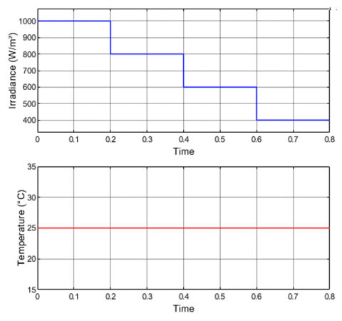
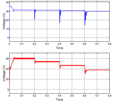
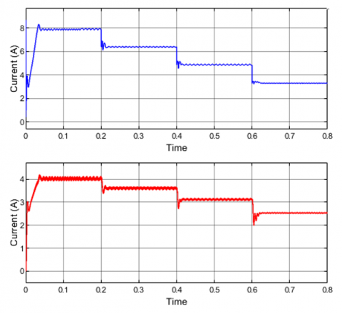
Figure 16 represent irradiance and temperature profiles. We focus on the changing irradiance with a fixed temperature of 25℃. Blue line in Figures 17-19 represents the PV array's initial condition, while the red line represents the boost and load variables.
Figure 17 shows a "ladder down-shape" profile, indicating that the PV power varies as the different irradiance levels.
At t=0.1 s, when the irradiance is 1000W/m², the power at the maximum power point is approximately 250W. However, when the irradiance decreases to 800W/m² at t=0.2s, the power drops to around 200W due to reduced irradiance reception. Both graphs demonstrate similar outputs in controlling the PV power to maintain stability and avoid voltage fluctuations.
Figure 16. Changing irradiance and fixed temperature
Figure 17. PV power and load power
The explanation for these power outputs is provided in Figures 18 and 19. Figure 18 shows that at an irradiance of 1000W/m², the PV voltage is 31.54V, while the load voltage is 60.95V, as a result of the boost converter's nature to step up the system voltage. Similarly, Figure19 illustrates that the PV current is 7.85 A, and the load current is 4.064 A, which is less than the input current due to the voltage increase in the boost converter at 1000W/m². This relationship aligns with Ohm's Law, where power is the product of voltage and current, as stated in the P&O subsystem. To achieve the maximum power point, the voltage or current needs to decrease.
As the load voltage decreases with the solar irradiance, to maintain the PV voltage at the maximum level, the controller must consequently reduce the duty ratio of the switching signal. Figure 20 shows clearly the duty cycle profile follows the solar irradiance profile.
Figure 18. PV voltage and load voltage
Figure 19. PV current and load current
Figure 20. Duty cycle profile
In this paper an improved P&O MPPT strategy, based on a fuzzy variable step size controller, was designed and implemented to overwhelm the limitations of the conventional fixed step P&O. The obtained simulation results demonstrate that the recommended method reduces steady-state power oscillations around the MPP and demonstrates a faster response to irradiance changes.
The main objectives of this work were to evaluate and simulate the variable step size modifications of the P&O algorithm in a PV system. Three criteria were analyzed, including power generated, current, voltage, and duty ratio, by comparing them with the P-V and I-V curve characteristics of the PV panel. The results reveal a trade-off between minimizing tracking time towards the MPP and reducing the oscillations of the PV power around the MPP, solving some of the problems associated to fixed step size in MPPT. Consequently, the primary goal of this paper, which aimed to examine the effectiveness of the improved P&O based fuzzy logic controller with a variable step size in a PV system has been achieved, see Table 3.
So the contributions of this paper are as follows:
Although the proposed strategy has given good results for PV MPP tracking, its potential and limitations for this application need further research, to be fully understood. Nonetheless efficiency could be significantly improved by using optimization-based technique of the fuzzy rules.
Practically, the proposed technique could improve the efficiency of PV installation and minimize the cost.
In future work, MPPT based optimization technique will be evaluated on an experimental hardware platform using a PV emulator. Also MPPT based on deep learning will be developed and compared to the proposed technique.
Table 3. Key results
|
|
Irradiance (W/m²) and 25℃ |
|||||||
|
1000 |
800 |
600 |
400 |
|||||
|
PV |
Load |
PV |
Load |
PV |
Load |
PV |
Load |
|
|
P (W) |
247 |
247 |
199 |
198 |
149 |
149 |
98 |
98 |
|
V (V) |
31 |
60 |
31 |
54 |
30 |
47 |
29 |
38 |
|
I (A) |
7.85 |
4.064 |
6.388 |
3.636 |
4.827 |
3.153 |
3.298 |
2.56 |
|
D |
0.4908 |
0.4507 |
0.3805 |
0.2595 |
||||
[1] Abo-Sennah, M.A., El-Dabah, M.A., Mansour, A.E.B. (2021). Maximum power point tracking techniques for photovoltaic systems: A comparative study. International Journal of Electrical & Computer Engineering (2088-8708), 11(1): 57-73. https://doi.org/10.11591/ijece.v11i1.pp57-73
[2] Abualigah, L., Zitar, R.A., Almotairi, K.H., Hussein, A.M., Abd Elaziz, M., Nikoo, M.R., Gandomi, A.H. (2022). Wind, solar, and photovoltaic renewable energy systems with and without energy storage optimization: A survey of advanced machine learning and deep learning techniques. Energies, 15(2): 578. https://doi.org/10.3390/en15020578
[3] Kumar, R., Singh, S.K. (2018). Solar photovoltaic modeling and simulation: As a renewable energy solution. Energy Reports, 4: 701-712. https://doi.org/10.1016/j.egyr.2018.09.008
[4] Nadkarni, S.S., Angadi, S., Raju, A.B. (2018). Simulation and analysis of MPPT algorithms for solar PV based charging station. In 2018 International Conference on Computational Techniques, Electronics and Mechanical Systems (CTEMS), Belgaum, India, pp. 45-50. https://doi.org/10.1109/CTEMS.2018.8769191
[5] Elnaghi, B.E., Dessouki, M.E., Abd-Alwahab, M.N., Elkholy, E.E. (2020). Development and implementation of two-stage boost converter for single-phase inverter without transformer for PV systems. International Journal of Electrical & Computer Engineering, (2088-8708), 10(1). https://doi.org/10.11591/ijece.v10i1.pp660-669
[6] Mohapatra, A., Nayak, B., Saiprakash, C. (2019). Adaptive perturb & observe MPPT for PV system with experimental validation. In 2019 IEEE International Conference on Sustainable Energy Technologies and Systems (ICSETS), Bhubaneswar, India, pp. 257-261. https://doi.org/10.1109/ICSETS.2019.8744819
[7] Pilakkat, D., Kanthalakshmi, S. (2020). Study of the importance of MPPT algorithm for photovoltaic systems under abrupt change in irradiance and temperature conditions. WSEAS Transactions on Power Systems, 15: 8-20. https://doi.org/10.37394/232016.2020.15.2
[8] Ammayappan, B.S., Seyezhai, R. (2020). Comparative analysis of maximum power point tracking algorithms for photovoltaic applications. WSEAS Transactions on Power Systems, 15: 161-171. https://doi.org/10.37394/232016.2020.15.20
[9] Samosir, A.S., Gusmedi, H., Purwiyanti, S., Komalasari, E. (2018). Modeling and simulation of fuzzy logic based maximum power point tracking (MPPT) for PV application. International Journal of Electrical and Computer Engineering, 8(3): 1315-1323.
[10] Al-Gizi, A., Miry, A.H., Shehab, M.A. (2022). Optimization of fuzzy photovoltaic maximum power point tracking controller using chimp algorithm. International Journal of Electrical and Computer Engineering, 12(5): 4549-4558. https://doi.org/10.11591/ijece.v12i5.pp4549-4558
[11] Pandey, N.K., Pachauri, R.K., Choudhury, S., Sahu, R.K. (2023). Asymmetrical interval Type-2 Fuzzy logic controller based MPPT for PV system under sudden irradiance changes. Materials Today: Proceedings, 80: 710-716. https://doi.org/10.1016/j.matpr.2022.11.074
[12] Arulmurugan, R. (2020). Optimization of perturb and observe based fuzzy logic MPPT controller for independent PV solar system. WSEAS Transactions on Power Systems, 19: 159-167. https://doi.org/10.37394/23202.2020.19.21
[13] Al-Majidi, S.D., Abbod, M.F., Al-Raweshidy, H.S. (2018). A modified P&O-MPPT based on pythagorean theorem and CV-MPPT for PV Systems. In 2018 53rd International Universities Power Engineering Conference (UPEC), Glasgow, UK, pp. 1-6. https://doi.org/10.1109/UPEC.2018.8542049
[14] Elbarbary, Z.M.S., Alranini, M.A. (2021). Review of maximum power point tracking algorithms of PV system. Frontiers in Engineering and Built Environment, 1(1): 68-80. https://doi.org/10.1108/FEBE-03-2021-0019
[15] Arulmurugan, R. (2016). Comparative evaluation of new FLC controller based MPPT for a DC to DC buck-boost zeta converter. WSEAS Transactions on Power Systems, 11, 27-34.
[16] Yilmaz, U., Kircay, A., Borekci, S. (2018). PV system fuzzy logic MPPT method and PI control as a charge controller. Renewable and Sustainable Energy Reviews, 81: 994-1001. https://doi.org/10.1016/j.rser.2017.08.048
[17] Singh, S., Manna, S., Mansoori, M.I.H., Akella, A.K. (2020). Implementation of perturb & observe MPPT technique using boost converter in PV system. In 2020 International Conference on Computational Intelligence for Smart Power System and Sustainable Energy (CISPSSE), Keonjhar, India, pp. 1-4. https://doi.org/10.1109/CISPSSE49931.2020.9212203
[18] Jiang, M., Ghahremani, M., Dadfar, S., Chi, H., Abdallah, Y.N., Furukawa, N. (2021). A novel combinatorial hybrid SFL-PS algorithm based neural network with perturb and observe for the MPPT controller of a hybrid PV-storage system. Control Engineering Practice, 114: 104880. https://doi.org/10.1016/j.conengprac.2021.104880
[19] Kumar, N., Hussain, I., Singh, B., Panigrahi, B.K. (2017). Framework of maximum power extraction from solar PV panel using self predictive perturb and observe algorithm. IEEE Transactions on Sustainable Energy, 9(2): 895-903. https://doi.org/10.1109/TSTE.2017.2764266
[20] Ali, M.N., Mahmoud, K., Lehtonen, M., Darwish, M.M. (2021). An efficient fuzzy-logic based variable-step incremental conductance MPPT method for grid-connected PV systems. IEEE Access, 9: 26420-26430. https://doi.org/10.1109/ACCESS.2021.3058052
[21] Abdourraziq, M.A., Maaroufi, M., Ouassaid, M., Tlemcani, M. (2017). Maximum power point tracking method based fuzzy logic control for photovoltaic systems. WSEAS Transactions on Power Systems, 12: 324-334.
[22] Li, X., Wang, Q., Wen, H., Xiao, W. (2019). Comprehensive studies on operational principles for maximum power point tracking in photovoltaic systems. IEEE Access, 7: 121407-121420. https://doi.org/10.1109/ACCESS.2019.2937100
[23] Silva, J.F., Pinto, S.F. (2018). Linear and nonlinear control of switching power converters. In Power Electronics Handbook. Butterworth-Heinemann, pp. 1141-1220. https://doi.org/10.1016/B978-0-12-811407-0.00039-8
[24] Mamdani, E.H., Assilian, S. (1975). An experiment in linguistic synthesis with a fuzzy logic controller. International Journal of Man-Machine Studies, 7(1): 1-13.
[25] Sugeno, M. (1985). Industrial applications of fuzzy control, Amsterdam, New York, NY, USA, Elsevier Science Pub. Co.