Walid Mohammed Kacemi*![]() | Elhadj Bounadja
| Elhadj Bounadja![]() | Abdelkadir Belhadj Djilali
| Abdelkadir Belhadj Djilali![]() | Atif Iqbal
| Atif Iqbal![]() | Khaled Fettah
| Khaled Fettah![]()
© 2024 The authors. This article is published by IIETA and is licensed under the CC BY 4.0 license (http://creativecommons.org/licenses/by/4.0/).
OPEN ACCESS
In recent years, the wind conversion system (WCS) sector has witnessed a notable surge in the recognition of robust control methodologies. This paper undertakes a thorough investigation into a resilient control system customized for a self-contained WCS, seamlessly integrating a hybrid excitation synchronous generator (HESG) linked to an independent load during the crucial Maximum Power Point Tracking (MPPT) phase. The motivation for this study lies in the growing integration of HESG technology within WCS frameworks. Addressing a vital gap in prior research, which often focused on the structural intricacies of HESG while neglecting their operational efficacy, this work aims to rectify this imbalance. Traditional control systems have limitations for WCS applications. In particular, proportional-integral (PI) controllers struggle with power quality and system performance. In this context, our research presents a MATLAB-Simulink-based equivalent model of WCS that has been rigorously developed. A novel control strategy based on Backstepping Control (BSC) is proposed as a countermeasure to existing challenges. This method not only improves WCS control efficiency but also demonstrates its proficiency in optimizing MPPT. The simulations indicate that the suggested control system outperforms the PI system regarding power fluctuations, response time, overshoot, and durability. This result demonstrates its potential to improve the effectiveness of renewable energy production.
Backstepping Control (BSC), diode bridge rectifier, isolated load, hybrid excitation synchronous generator (HESG), wind conversion system (WCS)
In response to the depletion of fossil fuel reserves, their high costs, and environmental concerns, it has become universally necessary to urgently reduce carbon emissions and prioritize the protection of nature [1]. Therefore, the need to shift to renewable sources of energy, including solar and geothermal energy, especially wind energy, has become urgent. Wind energy, known for its cost-effectiveness and environmental compatibility [2], is one such sustainable alternative. In particular, the environmental impact of air mills is highlighted because they exploit energy efficiently without causing water or soil pollution or exacerbating the impact of global warming [3].
In today’s wind landscape, synchronous and induction machines dominate as dominant generators [4]. While the induction of spiral rotors and synchronous machines has peaked in terms of power and power density, the search for the most efficient generator configuration remains an unwavering pursuit, especially after maximum energy capture at low wind speeds [5]. In the current context, synchronous machines continue to demonstrate their competitive advantage in wind power generation [6]. Most of these machines use permanent magnets (PM) [7] or a wound rotor. Remarkably, the permanent magnet synchronous machine is rapidly gaining popularity due to its superior performance and increased power density. The integration of PM instead of the DC field winding in the rotor increases efficiency, power density, and response speed due to the absence of rotor copper losses [8]. Tao et al. [9] conducted a comparative analysis of induction and synchronous generators for standalone wind turbines, positing a more congruent function for PM machines in such configurations. Nevertheless, it is crucial to acknowledge that the permanent magnetic flux generated by PMs remains a significant limitation. As a remedial approach, this paper suggests the hybrid excitation synchronous generator (HESG) as a novel alternative for wind energy generation. In contrast to conventional PM generators, the HESG facilitates flux modulation via its intrinsic excitation coils, eliminating the need for complex power electronics for speed modulation in favor of a simple DC/DC converter [10]. The inherent duality of the HESG excitation mechanism ensures constant reliability and provides a source of constant flux in a variety of conditions. This study examines the applicability and advantages of the HESG approach in the wind industry [11].
With the increasing use of HESG in wind conversion systems, this research seeks to expand our knowledge of its potential and applications [12]. Historically, the engine's modus operandi for this device has been the primary focus of research [13], with major applications in electric and hybrid propulsion systems [14]. On the other hand, the focus of research efforts has recently shifted to its potential in generator formation. For example, Mseddi [15] discusses its application in marine diesel groups, while Patin et al. [16] studies its applicability in small hydropower installations. Significantly, within this growing range of applications, a number of research proposals emphasize the potential of HESG in wind energy investment [17].
In this paper, a new approach is presented to increase the operational efficiency of a wind energy conversion system by integrating a three-phase hybrid excitation synchronous generator connected to a diode bridge rectifier. This configuration is designed to operate as a direct current (DC) generator, especially for isolated loads in embedded systems. Conventional control methods, including proportional-integral (PI) controllers, have historically shown some shortcomings in energy quality and overall performance within wind energy conversion systems (WPCS). In response to these limitations, our research delineates an innovative variable structure control strategy anchored in the principles of Backstepping Control (BSC). This advanced control paradigm is designed to bolster the efficacy of traditional control mechanisms in WPCS, centralizing its focus on preserving a consistent proficiency in maximum power point monitoring (MPPT).
This paper aims to demonstrate the advantages of a novel BSC strategy for HESG in wind energy systems, specifically targeting improvements in MPPT efficiency and robustness to parameter uncertainties. The effective tracking of optimal power in zone 2 (refer to Figure 1), along with the regulation of the generator speed in zone 3 of the analyzed structure, is achieved through the utilization of an internal current loop and an external speed loop. A comparison between the two controllers (PI and BSC) is conducted, focusing on maximizing the captured wind energy in the second operating zone and minimizing the transient loads on the drive train in the third zone. The robustness of the WCS to uncertainties in parameters and nonlinearities is assessed across diverse wind profiles, encompassing both step changes and stochastic variations, for both controllers.
Figure 1. Optimal turbine power vs wind speed of a 2KW WCS
Extensive simulations and system modeling were conducted within the MATLAB/Simulink environment to meticulously validate the proposed BSC method and rigorously assess its real-world applicability in power generation endeavors. The insightful findings of these analytical evaluations definitively demonstrate the efficacy of this novel control technique, providing compelling evidence of its potential to significantly enhance the performance and efficiency of wind energy conversion systems. Figure 2 visually represents the architectural configuration of the conversion apparatus, facilitating an intuitive comprehension of its design and functionality.
Figure 2. Wind power generation system
The structure of this manuscript is systematically organized as follows: Section 2 meticulously discusses the modeling aspects of the HESG-based WCS, including an in-depth analysis of HESG classification, the dynamics of wind turbine modeling complemented by its MPPT, and the nuanced modeling of HESG. In Section 3, we concentrate on the foundational principles of HESG control, introducing an advanced BSC strategy specifically designed for the integration of HESG within WCS. Section 4 conducts extensive numerical simulations of the unified system, as visually represented in Figure 1, with the objective of authenticating the efficiency and critically evaluating the performance metrics of the newly proposed control paradigm. The manuscript reaches its culmination in Section 5, where conclusive insights are articulated and prospective research trajectories are envisaged, serving as a compass for future explorations in this domain.
2.1 Model of the turbine
The mathematical formulation for the aerodynamic power extracted by the wind turbine is articulated as follows [18].
$P_t=C_p P_v=\frac{1}{2} \rho \pi R^2 v^3 C_p(\lambda, \beta)$ (1)
In the equation, v denotes the wind speed, while λ symbolizes the tip-speed ratio, which can be articulated as:
$\lambda=\frac{R \cdot \Omega_t}{v}$ (2)
According to Betz's Law, no wind turbine can capture more than 59.3% (approximately 16/27) of the kinetic energy in the wind. This theoretical limit is known as the Betz limit or Betz coefficient. The "Betz limit," also known as the theoretical maximum for the power coefficient (Cp), is 0.475. However, this value could be more practical. Utilize Eq. (3) to determine the value of this coefficient [19]:
The following expression is widely used and simple to alter for power coefficient calculations in modern turbines.
$\begin{gathered}C_p(\lambda, \beta)=0.5\left[116\left(\frac{1}{\lambda_i}\right)-0.4 \beta-\right. 5] \exp \left[-21\left(\frac{1}{\lambda_i}\right)\right]+0.0068 \lambda\end{gathered}$ (3)
With:
$\frac{1}{\lambda_i}=\frac{1}{\lambda+0.08 \beta}-\frac{0.035}{\beta^3+1}$ (4)
Utilizing the foundational principles of dynamics, one can derive the mechanical equation for our wind system as follows:
$J \frac{d \Omega_g}{d t}=T_{m e ́ c}=T_g-T_{e m}-T_f$ (5)
Using Eq. (1) through (5), a functional block diagram model is constructed for the turbine. In the comprehensive block diagram depicted in Figure 3 both the aerodynamic and mechanical attributes of the wind turbine are succinctly modeled. The diagram lucidly illustrates the capability to modulate the generator’s rotational speed, denoted as Ωg, which, by extension, affects the turbine’s speed. This modulation can be achieved via two distinct methods: firstly, by manipulating the blades pitch angle, represented as β, and secondly, by varying the electromagnetic torque, Tem, inherent to the HESG system. Notably, the wind speed, represented as v, is introduced into this model as an external disturbance, thereby acknowledging its potential to disrupt the system’s stability.
Figure 3. Modelling of wind turbines
2.2 Model of HESG
The electromagnetic torque can be given as [13]:
$T_{e m}=p\left(\mathrm{M} \cdot i_q i_f+\left(L_d-L_q\right) i_d i_q+\psi_{p m} \cdot i_d\right)$ (6)
The dq frame representation offers a dynamic model of the HESG [20]:
$\left\{\begin{array}{l}\frac{d i_\mu}{d t}=\frac{1}{L_d}\left(V_d-R_s i_\mu+m R_s i_f+p \Omega\left(L_q i_q-\psi_{p m}\right)\right) \\ \frac{d i_q}{d t}=\frac{1}{L_q}\left(V_q-R_s i_q-p \Omega\left(L_d i_\mu\right)\right) \\ \frac{d i_f}{d t}=\frac{1}{\sigma L_f}\left(V_f-R_f i_f-m e_\mu\right) \\ \frac{d \Omega}{d t}=\frac{1}{J}\left(C_{e m}-C_r-f_v \Omega\right)\end{array}\right.$ (7)
2.3 Model of converters
Sim Power System instruments are utilized for the emulation of diode bridge rectifiers [21]. These tools enable an in-depth examination of commutation events and simplify the evaluation of controllers under circumstances that accurately replicate actual operational environments [22].
The structure of the DC-DC converter, also known as a chopper, is delineated by Eq. (8)
$\left(\begin{array}{l}I_L \\ V_C\end{array}\right)=\left(\begin{array}{cc}0 & -\frac{1}{L} \\ \frac{1}{C} & -\frac{1}{R C}\end{array}\right)\left(\begin{array}{l}I_L \\ V_c\end{array}\right)+\left(\begin{array}{cc}0 & \frac{1}{L} \\ -\frac{1}{C} & 0\end{array}\right)\left(\begin{array}{l}I_L \\ V_C\end{array}\right)+\left(\begin{array}{l}\frac{E}{L} \\ 0\end{array}\right)$ (8)
Given the inherent nonlinearity entwined with the dynamics of wind turbines and the intricate complexities ushered in by HESG, control strategy such as PI controllers may find itself ill-equipped to grapple with the myriad operational challenges. Enter BSC, a formidable solution that, owing to its innate in managing nonlinear systems, rises to the occasion. Its recursive nature allows for the continuous fine-tuning and optimization of control inputs in real-time, ensuring the WCS operates in close proximity to its pinnacle efficiency [23]. A complex control algorithm is conceived to determine the appropriate excitation current that corresponds to the empirically observed turbine speed. This computational strategy is incorporated into the comprehensive control framework, which entails continuous monitoring and recalibration of the excitation current. By orchestrating this adjustment of the excitation current based on the turbine's dynamics, the HESG is poised to accomplish exceptional operational efficacy and power transference in the context of wind energy conversion [24, 25].
3.1 Mechanical speed control
Step 1: Define the error variable as follows:
$e(t)=\Omega_g{ }^*-\Omega_g$ (9)
Step 2: The error's derivative with respect to time is:
$\dot{e}\left(\Omega_t\right)=\dot{\Omega}_g-\dot{\Omega}_g^*$ (10)
Step 3: Choose a Lyapunov function:
$V=\frac{1}{2} e^2$ (11)
Step 4: Compute the time derivative of the Lyapunov function using the system dynamics and control inputs:
$\dot{V}(e)=e\left(\Omega_g\right)\left(\frac{1}{j_t}\left(T_g-T_{e m}-f_t \Omega_g\right)-k_1 e\left(\Omega_g\right)-\dot{\Omega}_g\right)$ (12)
Step 5: Formulate the control law using BSC:
$\dot{\Omega}_g=\frac{1}{J_t}\left(T_g-T_{e m}-f_t \Omega_g\right)+k_1 e\left(\Omega_g\right)$ (13)
Step 6: Stability Analysis
Starting with the Lyapunov derivative:
$\begin{gathered}\dot{V}(e)=e\left(\Omega_g\right)\left(\frac{1}{J_t}\left(T_g-T_{e m}-f_t \Omega_g\right)-k_1 e\left(\Omega_g\right)-\right. \left.\dot{\Omega}_g\right)\end{gathered}$ (14)
Substitute the control law into the Lyapunov derivative:
$\begin{aligned} & V^*(e)= e\left(\Omega_g\right)\left(\begin{array}{c}\frac{1}{J_t}\left(T_g-T_{e m}-f_t \Omega_g\right)-k_1 e- \\ \left(\frac{1}{J_t}\left(T_g-T_{e m}-f_t \Omega_g\right)+k_1 e\left(\Omega_g\right)\right)\end{array}\right)\end{aligned}$ (15)
Now, let's simplify the expression:
$\begin{aligned} & V^*(e)= e\left(\Omega_g\right)\left(\begin{array}{c}\frac{1}{J_t}\left(T_g-T_{e m}-f_t \Omega_g\right)-k_1 e\left(\Omega_g\right)- \\ \frac{1}{J_t}\left(T_g-T_{e m}-f_t \Omega_g\right)-k_1 e\left(\Omega_g\right)\end{array}\right)\end{aligned}$ (16)
Final simplification:
$V \dot{(e)}=-k_1 e\left(\Omega_g\right)^2<0$ (17)
The incorporation of the positive control gain $k_1$ is vital to improving system stability. An increased value of $k_1$ enhances the stabilizing impact of the control rule, hence fostering a more resilient stability response in the presence of disturbances.
3.2 Excitation current control
Step 1: The error dynamics can be characterized by the equation:
$e(t)=I_f^*-I_f$ (18)
Step 2: When introducing error dynamics, we obtain:
$\dot{e}(t)=\dot{I}_f^*-\dot{I}_f$ (19)
Step 3: Choose a Lyapunov function:
$V=\frac{1}{2} e^2$ (20)
Step 4: Differentiating $V$ with respect to time yields $\dot{V}=e \dot{e}$, which, when substituted with the error dynamics, provides
$V \dot{(e)}=e\left(I_f\right)\left(\frac{1}{\sigma L_f}\left(V_f-R_f i_f-m e_\mu\right)-k_1 e\left(I_f\right)-\right.\left.\dot{I}_f\right)$ (21)
Step 5: At this juncture, a control law u is devised as
$\dot{I}_f=\frac{1}{\sigma L_f}\left(V_f-R_f i_f-m e_\mu\right)$ (22)
Step 6: Stability Analysis
Starting with the Lyapunov derivative:
$\begin{gathered}V \dot{(e)}=e\left(I_f\right)\left(\frac{1}{\sigma L_f}\left(V_f-R_f i_f-m e_\mu\right)-k_1 e\left(I_f\right)-\right. \left.\frac{1}{\sigma L_f}\left(V_f-R_f i_f-m e_\mu\right)\right)\end{gathered}$ (23)
Final simplification:
$V \dot{(e)}=-k_1 e\left(I_f\right)^2<0$ (24)
The system in question will exhibit stability when a positive constant, denoted as $k_1$. Figure 4 depicts the Excitation current control
Figure 4. Excitation current control
where, Le is the inductance of the excitation coils. (K0=5) is a constant coefficient that represents the DC/DC converter's gain. The Blondel coefficient, denoted as $\sigma$ is given by Eq. (25). Figure 5 depicts the control of system.
$\sigma=1-\frac{3 M^2}{L_d L_f}$ (25)
Figure 5. HESG-based WCS control
The MATLAB-simulated BSC technique applied to the HESG-driven WCS as described in Section 3 was critically evaluated and compared to the performance of conventional PI control. The operational parameters of the system were analyzed, providing insights into its efficacy and dependability. Table 1 contains the compiled HESG-WCS parameters:
Table 1. Parameters of the HESG-WCS
|
System |
Parameters |
|
HESG |
f = 50 Hz, p = 6, Rs= 1 Ω, Rf = 1.35Ω, Ld=Lq= 6 mH, Lf = 4.4 mH, M =4.9mH, phi=0.04Wb |
|
Turbine |
R = 1.8m, G =8, λopt= 8,1, Cpmax = 0.48, Jt=0.0136, ft=0 |
In this study, a comprehensive comparison of two controllers, one employing BSC and the other employing a PI controller, is undertaken in the dynamic contexts of zones 2 and 3 within wind energy systems.
Test 1: Robustness analysis of excitation current: The effectiveness of the current controller is evaluated through simulation. As depicted in Figure 4, the synthesis procedure for the controller overlooks commutation effects and space harmonics. Specifically, the converter is represented as a pure gain (K0), and the generator is modeled in the d-q reference frame with an assumption of a first harmonic model. Figure 6 serves as evidence that the BSC exhibits robustness against harmonics' effects. When the PI control is reversed, a substantial overshoot is observed, underscoring the superior performance of the BSC compared to the PI control.
Figure 6. Analysis of the current controller's robustness
Test 2: In test 2 a structured approach is adopted, commencing with a controlled wind input comprising four distinct stages (as seen in Figure 7), transitioning into a nonlinear model in zone 2, intended to rigorously assess the adaptability of the controllers to abrupt wind profile changes. The primary focus of this analysis revolves around key performance indicators, notably settling time and overshoot. Replicating the test in zone 3 extends the examination to evaluate the transient stability inherent in the wind energy system's drive train dynamics. Furthermore, Figure 8 provides an insightful view of the generator's rotational speeds as influenced by a stepped wind profile. The conclusive results unambiguously affirm the superior performance of the BSC, effectively minimizing static error to near-zero levels and ensuring well-damped oscillations across all operating conditions with a maximum overshoot well within the acceptable limit of 5%, in contrast, the PI controller exhibits increased overshoot 20%, indicative of its relatively diminished stability. Both controllers exhibit consistent settling times across a range of speed levels, signifying commendable performance. In the steady-state regime, the BSC offers slightly enhanced precision, contributing to minor differences in wind power extraction, as observed in Figure 9.
Figure 7. Wind speed (m/s) (zone 2, step profile)
Figure 8. Mechanical speed (m/s) (zone 2, step profile)
Figure 9. Aerodynamic powers (W) (zone 2, step profile)
Figure 10. Wind speed (m/s) (zone 3, step profile)
Figure 11. Mechanical speed (m/s) (zone 3, step profile)
Figure 12. Aerodynamic powers (W) (zone 3, step profile)
In zone three, characterized by heightened mechanical stress, a stability imperative arises for maintaining consistent rotational speed. Figures 10 and 11 illustrate the wind profile and velocity response, respectively. The utilization of the BSC controller results in significantly reduced angular velocity fluctuations, indicating its superior closed-loop performance. Figure 12, depicting turbine power, reveals notable peaks linked to wind velocity shifts, particularly evident in the challenging step wind profile. While turbulence is possible in actual conditions, it seldom reaches the extremes induced by these step changes, as confirmed by the absence of such peaks under a stochastic wind profile.
Test 3: The initial and second tests inadequately validate the controllers, lacking realism in simulating actual meteorological wind conditions. To address this, the system undergoes additional assessment using a stochastic wind profile, as depicted in Figure 13. Simulations based on this profile, shown in Figures 14 and 15, demonstrate that both controllers successfully maintain reference tracking and effectively manage the full-bridge rectifier and DC/DC converter. Additionally, they exhibit resilience against harmonic current fluctuations in the generator. Notably, the BSC strategy surpasses the traditional PI controller in tracking optimal rotational speed, as evidenced by the marginal power difference in Figure 14. These results underscore the potential of the BSC controller to enhance wind energy harvesting efficiency, offering promising practical implementation benefits.
Figure 13. Wind speed(m/s) (zone 2, stochastic profile)
Figure 14. Aerodynamic power(W) (zone 2, stochastic profile)
Figure 15. Mechanical speed(m/s) (zone 2, stochastic profile)
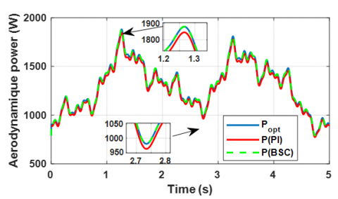
In the third zone, where a stochastic wind profile is shown in Figure 16, it was seen that the BSC controller works better, especially when it comes to reducing mechanical vibrations and making sure there is less oscillation, as shown in Figure 17 In these figures, the rotational speed exhibits more effectively damped oscillations in comparison to other methods under consideration. Additionally, Figure 18 shows the turbine's maximum power output, which is 2 kW
Figure 16. Wind speed(m/s) (zone 3, stochastic profile)
Figure 17. Mechanical speed(m/s) (zone 3, stochastic profile)
Figure 18. Aerodynamic power(W) (zone 3, stochastic profile)
When comparing the performance of BSC and PI, it is evident that the superiority of the backward approach lies in its inherent ability to automatically adjust to the intricate and ever-changing characteristics of the wind power system. The BSC demonstrates exceptional proficiency in efficiently managing abrupt variations in the wind profile, showcasing its remarkable capacity to handle non-linearity successfully. The BSC offers strong robustness to external disturbances and precise tracking skills, reducing steady-state error, well-damped oscillations, and a maximum overshoot that remains below the acceptable threshold of 5%. In contrast, although the PI control is praised in some scenarios, it shows a 20% increase in overshoot, reflecting its low relative stability under dynamic conditions. The control outperforms the PI controller in effectively handling the complexities of drivetrain dynamics in a wind energy system and demonstrating high accuracy in steady-state operation.
Table 2 provides a comprehensive comparison of BSC and PI control, based on simulation experiments. These meticulously executed simulations bolster the credibility and dependability of the results by emphasizing key performance metrics such as system robustness, control precision, and trajectory fidelity.
Table 2. Comparative results
|
Performance Criteria |
PI Control |
BSC |
|
Simplicity |
Simple |
Complicated |
|
Dynamic responses |
Medium |
Fast |
|
Rise time |
Slower |
Faster |
|
Settling time |
Longer |
Shorter |
|
Overshoot |
Higher |
Lower |
|
Steady-State error |
Can exist |
Can be minimized |
|
Robustness to disturbances |
Moderate |
Higher |
|
Control action |
Continuous |
Continuous |
|
Mechanical speed quality |
Acceptable |
Good |
|
Simulation complexity |
Lower |
Higher |
The simulation results validate that the BSC in wind power conversion systems improves efficiency, stability, and reliability. These advancements signify a significant leap in enhancing the efficiency of wind power systems to achieve better sustainability and competitiveness.
The efficacy of BSC manifests in tangible advantages in the real world, such as enhanced energy efficiency and heightened reliability. Additionally, the regulated movements noticed while using backstepping control have the potential to result in decreased maintenance expenses. The flexibility of wind energy systems maximizes the extraction of wind power, minimizes errors and disturbances, and eventually improves the overall performance and sustainability of these systems.
This study thoroughly investigates control strategies in wind energy systems, focusing on these two zones. The BSC and PI controller are compared within a well-structured modeling framework considering electronic commutations and space harmonics. The methodology began with a four-stage controlled wind input and transitioned into a nonlinear model, assessing how these controllers adapt to sudden wind profile changes. The primary focus was key performance indicators, including settling time and overshoot. The simulation results confirm that using BSC in wind power conversion systems enhances efficiency, stability, and dependability. These developments represent a substantial breakthrough in improving the effectiveness of wind power systems to attain greater sustainability and competitiveness. The BSC, with a maximum overshoot well within the acceptable limit of 5%, offers strong robustness to external disturbances and precise tracking, reducing steady-state error. It also demonstrated better responsiveness to rapid wind changes.
In contrast, the PI controller exhibits an increased overshoot of 20%, reflecting its low relative stability under dynamic conditions. The results demonstrated the ability to accomplish robust incorporation of wind energy. We improved the control of MPPT by increasing its efficiency and enhancing its capacity to handle parameter uncertainty. As a future trajectory, HESG energy can be integrated into turbines in extended grid systems, focusing on improving control strategies to ensure grid stability with variable wind resources.
|
HESG |
hybrid excitation synchronous generator |
|
BSC |
backstepping control |
|
WCS |
wind conversion system |
|
POR |
point of regulation |
|
Cp |
coefficient of power |
|
$\Omega_{\mathrm{g}}$ |
generator's mechanical speed |
|
$\Omega_{\mathrm{t}}$ |
mechanical speed of the turbine |
|
λ |
speed ratio |
|
v |
wind speed |
[1] Gualtieri, G. (2019). A comprehensive review on wind resource extrapolation models applied in wind energy. Renewable and Sustainable Energy Reviews, 102(1364-0321): 215-233. https://doi.org/10.1016/j.rser.2018.12.015
[2] Gaughan, E., Fitzgerald, B. (2020). An assessment of the potential for co-located offshore wind and wave farms in Ireland. Energy, 200(0360-5442): 117526. https://doi.org/10.1016/j.energy.2020.117526
[3] Yassin, H.M., Abdel-Wahab, R.R., Hanafy, H.H. (2022). Active and reactive power control for dual excited synchronous generator in wind applications. IEEE Access, 10(2169-3536): 29172-29182. https://doi.org/10.1109/access.2022.3158621
[4] Hadi, A., Aly, H.H., Little, T. (2023). Harmonics forecasting of wind and solar hybrid model driven by DFIG and PMSG Using ANN and ANFIS. IEEE Access, 11(2169-3536): 55413-55424. https://doi.org/10.1109/access.2023.3253047
[5] Jia, S., Sun, P., Feng, S., Liang, D., Dong, X. (2022). A novel stator-pm consequent-pole dual stator/rotor armature winding flux modulated machine for multi-torque components. In 2022 IEEE 20th Biennial Conference on Electromagnetic Field Computation (CEFC), Denver, CO, USA, pp. 1-2. https://doi.org/10.1109/cefc55061.2022.9940780
[6] Liu, F., Wang, K., Li, J. (2021). Terminal Voltage Oriented control of excitation winding for new ac-excited hybrid excitation generator. In 2021 24th International Conference on Electrical Machines and Systems (ICEMS), Gyeongju, Korea, pp. 593-597. https://doi.org/10.23919/icems52562.2021.9634218
[7] Hlioui, S., Vido, L., Amara, Y., Gabsi, M., Miraoui, A., Lécrivain, M. (2008). Magnetic equivalent circuit model of a hybrid excitation synchronous machine. COMPEL - the International Journal for Computation and Mathematics in Electrical and Electronic Engineering, 27(5): 1000-1015. https://doi.org/10.1108/03321640810890735
[8] Kamiev, K., Nerg, J., Pyrhönen, J., Zaboin, V., Hrabovcová, V., Rafajdus, P. (2012). Hybrid excitation synchronous generators for island operation. IET Electric Power Applications, 6(1): 1-11. https://doi.org/10.1109/icelmach.2010.5608243
[9] Tao, W., Zhou, H., Liu, G. (2019). A novel stator-PM vernier fault-tolerant machine with consequent pole structure. In 2019 22nd International Conference on Electrical Machines and Systems (ICEMS), Harbin, China, pp. 1-4. https://doi.org/10.1109/icems.2019.8921765
[10] Mseddi, A., Le Ballois, S., Aloui, H., Vido, L. (2019). Robust control of a HESG for a wind energy application. Power Systems, 168(0378-7796): 250-260. https://doi.org/10.1016/j.epsr.2018.12.004
[11] Chakir, H., Ouadi, H., Giri, F. (2015). Output Feedback control of wind energy conversion system with hybrid excitation synchronous generator. IFAC-PapersOnLine, 48(11): 622-627. https://doi.org/10.1016/j.ifacol.2015.09.256
[12] Mseddi, A., Le Ballois, S., Aloui, H., Vido, L. (2020). Load mitigation and wind power maximization of a HESG-based wind conversion system. Renewable and Sustainable Energy, 12(5): 053305-053305. https://doi.org/10.1063/5.0009642
[13] Kacemi, W. M., Bounadja, E., Djilali, A.B. (2023). DC voltage output control of a hybrid synchronous generator-based wind turbine. International Journal of Advanced Natural Sciences and Engineering Researches, 7(4): 169-174. https://doi.org/10.59287/ijanser.645
[14] Gallas, H. (2021). Contribution à la Commande d’un Générateur de type Synchrone à Double Excitation dans le cas d’une Application Éolienne et Comparaison avec d'autres Architectures (Doctoral dissertation, CY Cergy Paris Université; Ecole Nationale d'Ingénieurs de Sfax). https://hal.science/tel-03433652.
[15] Mseddi, A. (2019). Modélisation et commande d’un générateur éolien à double excitation isolé en vue de l’amélioration de son rendement et de la diminution de la fatigue mécanique (Doctoral dissertation, Université de Cergy Pontoise; École nationale d'ingénieurs de Sfax (Tunisie)). https://theses.hal.science/tel-02888660.
[16] Patin, N., Vido, L., Monmasson, E., Louis, J.P., Gabsi, M., Lecrivain, M. (2008). Control of a hybrid excitation synchronous generator for aircraft applications. IEEE Transactions on Industrial Electronics, 55(10): 3772-3783. https://doi.org/10.1109/tie.2008.924030
[17] Berkoune, K., Ben Sedrine, E., Vido, L., Sandrine Le Ballois. (2017). Robust control of hybrid excitation synchronous generator for wind applications. Mathematics and Computers in Simulation, 131: 55-75. https://doi.org/10.1016/j.matcom.2015.10.002
[18] Berkani, A., Negadi, K., Allaoui, T., Marignetti, F. (2019). Sliding mode control of wind energy conversion system using dual star synchronous machine and three level converter. TECNICA ITALIANA-Italian Journal of Engineering Science, 63(2-4): 243-250. https://doi.org/10.18280/ti-ijes.632-418
[19] Bounadja, E., Boudjema, Z., Djahbar, A. (2019). A new DPC-SVM for matrix converter used in wind energy conversion system based on multiphase permanent magnet synchronous generator. Iranian Journal of Electrical & Electronic Engineering, 15(3): 352-363. https://doi.org/10.22068/ijeee.15.3.352
[20] Youcefa, B., Massoum, A., Barkat, S., Wira, P. (2019). Backstepping direct power control for power quality enhancement of grid-connected photovoltaic system implemented with PIL co-simulation technique. Advances in Modelling Series C. Automatic Control (theory and applications), 74(1): 1-14. https://doi.org/10.18280/ama_c.740101
[21] Sun, X., Meng, L., Liang, J., Li, S. (2019). Hybrid excitation synchronous motor feedback linearization decoupling sliding mode control. In 2019 22nd international conference on electrical machines and systems (ICEMS), Harbin, China, pp. 1-5. https://doi.org/10.1109/icems.2019.8922348
[22] Gallas, H., Mseddi, A., Le Ballois, S., Aloui, H., Vido, L. (2020). Modeling and control of 1.5 MW HESG-based wind conversion system: Advanced aerodynamic modeling. European Journal of Electrical Engineering, 22(2): 119-128. https://doi.org/10.18280/ejee.220205
[23] Salman, M.A., Kadhim, S.K. (2022). Optimal backstepping controller design for prosthetic knee joint. Journal Européen des Systèmes Automatisés, 55(1): 49-59. https://doi.org/10.18280/jesa.550105
[24] Bossoufi, B., Karim, M., Taoussi, M., Alami Aroussi, H., Bouderbala, M., Motahhir, S., Camara, M.B. (2020). DSPACE-based implementation for observer backstepping power control of DFIG wind turbine. IET Electric Power Applications, 14(12): 2395-2403. https://doi.org/10.1049/iet-epa.2020.0364
[25] Tao, G., Li, W. (2023). Higher-order tracking properties of adaptive backstepping control systems. Automatica, 153(0005-1098): 111019-111019. https://doi.org/10.1016/j.automatica.2023.111019