Ahmed Abd El Baset Abd El Halim*![]() | Ehab Hassan Eid Bayoumi
| Ehab Hassan Eid Bayoumi![]() | Walid El-Khattam
| Walid El-Khattam![]() | Amr Mohamed Ibrahim
| Amr Mohamed Ibrahim![]()
© 2023 IIETA. This article is published by IIETA and is licensed under the CC BY 4.0 license (http://creativecommons.org/licenses/by/4.0/).
OPEN ACCESS
Electric cars are becoming more and more popular. In 2019, 2.2 million electric cars were sold around the world, and that number increased in 2021 to 6.6 million. Microgrids prove to be a viable resolution to the challenge of integrating large-scale electric vehicles and renewable energy sources into the electric power system, given the exponential expansion of both industries and the demand for electric vehicles (EVs). Additionally, the principal policy objective of the government is to enhance the accessibility of public recharge stations designed to accommodate EVs. The study applies cutting-edge technologies to the development of fast-charging (FC) stations. Because DC charging offers unlimited power and quick power transfer, vehicle-to-grid technology can be implemented in a microgrid using DC power transmission. However, incorporating EVs into a microgrid system presents some operational difficulties. In this study, these difficulties are related to power quality (PQ) problems like harmonics in power systems, which have an impact on consumers as well as utilities. The efficacy of the control system was assessed through the simulation of design models employing MATLAB-based vector control and constant current-constant voltage (CC-CV) techniques. Through the reduction of the system's total harmonic distortion (THD), both strategies contribute to the enhancement of the PQ and performance of the control system as assessed by these simulations. Based on the findings, the controller demonstrated a decrease in THD and an enhancement in waveform quality, resulting in high accuracy and good performance. The DC-Bus receives power transmission from the AC network that is near the unity power factor (PF) and is distinguished by a sinusoidal current.
electric vehicles, fast charging station, power quality, vector control, constant current-constant volt control
Recent research and development efforts associated with the automotive sector, such as those listed in the studies [1-5], have placed a significant amount of emphasis on the design of forms of mobility that are both extremely energy efficient and completely free of emissions. When this is considered, it seems that traditional internal combustion engine (IC) vehicles can be most effectively replaced by electric and hybrid vehicles [6]. However, Certain crucial factors must be considered before EVs become widely available to the public. In our opinion, the biggest obstacle to the mainstream adoption of EVs is range anxiety. Another important objective in expanding the EV market is reducing the time needed to charge the vehicle. From this point of view, DC FC is an interesting chance. As stated in the study [7], DC FC can reduce the charging time to between 20 and 30 minutes.
According to the standards set forth by SAE J1772, there are three distinct levels of FC that are defined. Table 1 defines these three levels [8].
Electric Vehicle Supply Equipment (EVSE), an offboard charging device that serves as a conduit between the vehicle and supply, is used by all three FC DC levels.
FC of EVs has severe consequences on the network's PQ. PQ degradation is caused by numerous factors, the most prominent of which are harmonics in line currents, phase imbalance, voltage variations, DC offset, phantom loads, and stray fluxes [9]. Chargers of EV, due to their nonlinear nature, cause higher-order harmonics to be introduced into the line current that is drawn by them [10, 11]. These issues will have a negative impact on the efficiency and lifespan of the distribution network's hardware. In addition to this, the component of harmonic current that is being carried by the power transformers and cables causes extra I2R losses to be incurred. Many studies have been conducted about AC/DC converters' effects on PQ in EV chargers. PQ in the distribution system is analyzed in the study [12], which examines the effects of varying charging rates for EV batteries. Pan et al. [13] investigates the impact that harmonic currents have on a system that supports the FC of more than one EV. PQ from onboard chargers currently on the market is subpar because of harmonic components [14]. Line current with lower-order harmonics causes poor PF and wastes energy because of poor utilization of available voltage and amperage.
As there is a greater demand placed on the charging system, the harmonic distortion issue becomes more severe. In Basu et al. [15], a method is provided for reducing the injection of high-harmonic current into the distribution system. The standards that have been established to limit the number of harmonics that can be injected into a system are listed in the study [16]. These standards have been referred to as "harmonic injection limits." By making a few adjustments to the charger's management system and installing a voltage source inverter (VSI), which prevents the charger from feeding back any harmonic currents, the input current quality can be greatly improved. In addition, the current management of the converters is more successful than voltage control in assuring increased PF operating and reducing current transients [17]. In addition to this, the addition of FC stations to the grid might have several unfavorable effects on the distribution network [18]. An increase in network peak load is one of the most significant effects [19].
Table 1. The DC charging levels
|
Level |
Charging-Voltage (V) |
Charging-Current (A) |
Power-Rating (kW) |
|
1 |
200.00-450.00 |
80.00 |
36.00 |
|
2 |
200.00-450.00 |
200.00 |
90.00 |
|
3 |
200.00-600.00 |
400.00 |
240.00 |
Due to the considerable amount of volatility exhibited by the charging load, it is difficult to restrict the charging behavior to times when the load is low, which results in bigger variations in the system's peak [12]. This ultimately has a negative impact on the distribution network equipment's utilization efficiency. In addition to these impacts, there is also an increase in the amount of energy that is lost [20], as well as negative effects on the voltage profile and the distribution transformer [21, 22]. If the charging is not synchronized, there will be a significant impact in the form of overloaded conductors and cables, low voltages at the consumer end, and a violation of the planning limit [23]. It has been proposed that various demand-side management methods [24, 25] be implemented to deal with the increased power consumption by FC stations. One strategy is to use systems that store energy [26, 27]. Funke et al. [28] proposes a hybrid energy storage solution that employs a superconducting magnetic energy storage (SMES) system in conjunction with battery storage for a rapid charging station, thereby limiting the power magnitude and power change rate of a charging station using hybrid storage compensation. In the study [29], the FC station utilized a flywheel energy storage system for power balancing. This was done to reduce the negative effects of rapid charging on the utility grid by scaling the power peak.
FC infrastructure for EVs is given in this paper's accompanying model. Implementing a charging strategy using Constant Current-Constant Voltage (CC-CV) mode, as well as resolving PQ challenges associated with source-end harmonics, are covered. Finally, an ideal energy management strategy is proposed to reduce the strain on the power grid using renewable energy sources.
The purpose of the research is to develop two efficient control algorithms (vector control and CC-CV) for FC technology in the proposed charging station based on the concept of fast charging. To reduce total harmonic distortion (THD) and improve power quality and system performance. Finally, the proposed control techniques are evaluated.
The remaining sections of this article will be presented in the following order:
The Contributions in this paper are:
1. Shortening the charge time of an EV's battery.
2. Attempting to achieve a unity PF for the FC station connected to the utility grid.
3. Lower total harmonic distortion (THD) of the FC station source current
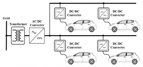
Figure 1 depicts the design for the suggested EV's FC station. As can be seen, the proposed architecture only requires a 3-phase AC-DC grid converter to be realized in the form of a DC-Bus, with DC-DC converters serving to connect the EVs that are being charged. Using a straightforward DC-DC converter, the DC-Bus enables the direct connection of Renewable Energy Source (RES) generation systems. When compared with the AC bus architecture, it is predicted that the overall conversion losses are reduced by fewer than 10% when using the DC-Bus architecture [30]. The grid is used to provide three-phase power. To reduce the voltage from the level of the distribution grid to the level at which EV batteries operate, a three-phase transformer is utilized. A three-phase AC/DC converter creates a DC-Bus by converting AC power to DC power. DC/DC converters are used to connect EVs to the DC-Bus so they can be charged. Numerous factors must be considered while planning an FC station, including:
Figure 1. Illustration of the proposed FC station
The following equation can be used to make an approximation of the rated capacity of FC station SR in VA:
$S_R=\frac{k_{\text {load }} N_{\text {slot }} P_{e v}}{\cos \varphi}$ (1)
where, $N_{{slot }}$ indicates how many slots are available for each car to charge, $\varphi$ indicates the system's PF, $P_{e v}$ indicates the maximum charging power rate for an $\mathrm{EV}$, and $k_{\text {load }}$ indicates an overload factor to take transient overloading into account. Typically, the grid voltage is used to determine the DC-Bus voltage $\left(v_{d c}\right)$. However, because the transformer connects to the grid, the bus voltage can be selected independently of the grid voltage level. However, the highest limit on the $v_{d c}$ is determined by the minimum modulation index $m_{\min }$ of the battery charger in addition to the battery's minimum voltage $V_{\text {minbat }}$. This is shown in Eq. (2):
$v_{d c} \leq \frac{v_{\min }^{b a t}}{m_{\min }}$ (2)
The amount of DC capacitance required to withstand the DC current ripples directly affects how stable the DC-Bus is. Since many chargers are required to connect to the DC-Bus, the DC ripple current could potentially be rather significant, necessitating a high capacitance value. In this study, the capacitance of the DC-Bus was determined by applying the approach described in the study [31] and considering both the rated active power as well as the rate at which the energy stored in the capacitor changed throughout the transient. The value of the capacitance can be found by applying Eq. (3):
$C_{d c}=\frac{s_R \cdot 2 n t \cdot \Delta p \cdot \cos \varphi}{V_{d c}^2 \cdot \Delta v}$ (3)
where, t represents the period of AC voltage, n is a multiple of t, Δp represents the DC power range of change, and Δv defines the permissible $v_{d c}$ range of change, in percentage, during transient.
As can be seen in Figure 2, the architecture that has been suggested for charging EV batteries makes use of two stages. The first stage consists of a 3-phase supply source, FEC, DC-Bus, and our proposed controller using the Vector control method. The second stage consists of a buck converter which is controlled using a constant voltage constant current control method and EV batteries.
The output voltage of the 3-phase AC supply is 380 VAC which is used as input to the FEC which is used to change the 3-phase AC voltage to DC voltage and helps to reduce the THD of the system and bring the PF closer to unity. The control used to help with this is the vector control method. The first stage controller is used to balance the DC-Bus voltage, which is the input to the second stage and represents the midpoint of the total charging system. It communicates directly with the electric vehicle batteries, which are charged using a DC buck converter. It is controlled by a CC-CV, which takes the values measured for batteries such as voltage, current, and SOC, and produces a duty cycle that regulates the buck converter based on them.
Figure 2. The first stage AC/DC is made up of a FEC which is responsible for feeding the second stage, which is made up of a buck converter and EV battery
Figure 3. FEC schematic
3.1 Front-end converter
Figure 3 shows the FEC is made up of a total of six switches, labeled $S_1$ through $S_6$. The converter accepts a 3-phase sinusoidal input voltage at line frequency and outputs a quasi-square wave at a high frequency. The FEC has been modulated using a variety of approaches, which have been researched in Basu et al. [15], and the study [15] provides a description of the modulation method that was suggested for use with this topology.
Despite any changes in the voltage provided by the supply, the goal of an AC/DC rectifier is to keep the DC link constant while also preserving the unity PF [16]. In this subsection, we analytically establish the connection between the input voltage and the constant voltage of the DC link. The formula is obtained in the d-q reference frame with the presumption of lossless switching and a symmetrical AC power supply. Figure 2 may be used to determine how to write the governing differential equations [17], which can be written as:
$L \frac{d i_{\varphi}}{d t}+R i_{\varphi}=E_{\varphi}-V_{d c}\left(S_{\varphi}-\frac{1}{3} \sum_{\varphi=1}^3 S_{\varphi}\right)$ (4)
$I_{d c}=\sum_{\varphi=1}^3 S_{\varphi} i_{\varphi}-C_{d c} \frac{d V_{d c}}{d t}$ (5)
where, $\varphi$ is the number of phases, $L$ is the inductance, and $i_{\varphi}$ is the line current. $R$ represents the overall resistance of the active rectifier switches as well as the parasitic resistance of the input filter; The phase voltage is denoted by $E_{\varphi} ; S_{\varphi}$ denotes the function of switching; $I_{d c}$ is the DC current that is produced by the $\mathrm{AC} / \mathrm{DC}$ rectifier, and $V_{d c}$ is the DC voltage that is generated by the $\mathrm{AC} / \mathrm{DC}$ rectifier.
When the switch is in the OFF position, $S_1, S_2$, and $S_3$ are all equal to zero, but when the switch is in the ON position, they are all equal to one. Eqs. (4) and (5) are rewritten using Clark's and Park's transformation to be interpreted in the stationary $d-q$ reference frame [5].
$V_d=L \frac{d i_d}{d t}+R i_d-L \omega i_q+S_d V_{d c}$ (6)
$V_q=L \frac{d i_q}{d t}+R i_q+L \omega i_d+S_q V_{d c}$ (7)
$I_{d c}=\frac{3}{2}\left(S_d i_d+S_q i_q\right)$ (8)
where, $\omega$ denotes the network frequency, $i_d, i_q, V_d$, and $V_q$ for current and voltage on the $d-q$ frame, respectively, and $S_d$ and $S_q$ are switching functions in the $d-q$ reference frame. Because of the high-switching frequency (SF) and the relatively low value of the input inductor compared to the value of the inductor on the battery side, the voltage drop at the inductor is not considered. In view of this, Eqs. (6) and (7) become [5]:
$V_d=R i_d-L \omega i_q+S_d V_{d c}$ (9)
$V_q=R i_q+L \omega i_d+S_q V_{d c}$ (10)
According to the d-q reference frame [5], the active and reactive powers are given as:
$P=\frac{3}{2}\left(V_d i_d+V_q i_q\right)$ (11)
$Q_{F C S}=\frac{3}{2}\left(V_d i_q-V_q i_d\right)$ (12)
where, Psub-FC sstations are the total active and reactive powers drawn by EV FC which also includes power losses in the system. In the steady state $\mathrm{i}_{\mathrm{q}}=0$ to approach the unity $\mathrm{PF}$ and $V_q=0$ because it is assumed that the d-q frame is spinning at speed and that the d-axis is pointing in the same direction as the supply voltage. Eq. (11) with the help of (8) and (9) become [5]:
$P=\frac{2 R I_{d c}^2}{3 S_d^2}+V_{d c} I_{d c}$ (13)
3.2 Buck converter
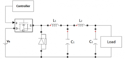
A DC-DC buck converter is essentially made up of power switches, like MOSFETs or IGBTs, which will govern pulses. A MOSFET serves as the power switch in the circuit design depicted in Figure 4, which steps down DC voltage from a high level to a low one [32]. This circuit's goal is to generate an entirely DC output.
A power conversion regulator is even more vulnerable to AC fluctuation and noise than a DC power supply. High-frequency waves are frequently coupled to the output voltage due to the switching and transition frequencies; because of this, a filter such as an LC low-pass filter was added to the fundamental circuit to generate a DC output voltage.
When the switch is turned on, the diode will undergo a process called reverse bias, which will cause it to supply energy to the load as well as the inductor. When the switch is in the OFF position, the diode will develop a forward bias, and current from the inductor will pass through the diode. A portion of the energy that it has stored will be transmitted to the load. With this circuit layout, low loads can be powered by high levels of voltage [33].
To charge the battery, the DC-DC buck converter must reduce the 800 VDC coming from the DC-Bus to the battery voltage. To prevent audible noise when using a capacitor of 100 μF, with a switching frequency 20 kHz. The gate pulses are generated by a control unit that implements the technique of constant-voltage constant-current.
Figure 4. Schematic diagram of a buck converter connected to a low-pass filter
3.3 $L i^{+}$ battery modeling
Most EVs use lithium-ion batteries because they are better than other types of batteries in terms of energy density, self-discharge, maintenance, and the number of times they can be charged and discharged [18]. Here, we use the battery's dynamic model [18] to express the connection between state-of-charge and terminal voltage as:
$V_b=V_o-r_b I_b-K \frac{Q}{Q-\int I_b d t} \int I_b d t+A e^{-B \int I_b d t}$ (14)
where, $V_o$ and $r_b$ are the voltage constant and the internal resistance in ohms of the battery, $K$ and $Q$ are the polarization constant in (V/Ah) and the rated capacity of the battery in (Ah) respectively, $\int I_b d t$ is extracted battery charge in (Ah), $A$ is exponential zone amplitude $(\mathrm{V}), B$ is the exponential zone time constant in $\left(\mathrm{Ah}^{-1}\right)$ and $I_b$ is the battery charging current in (A). Theoretically, $\int I_b d t=0$ when the battery is fullycharged. Therefore, Eq. (14) can be written as:
$V_b=V_o-r_b I_b-K \frac{Q\left(Q-\int I_b d t\right)}{\int I_b d t}+A e^{-B \int I_b d t}$ (15)
$S O C$ for the battery is seen in (16). $S O C_{i n}$ is regarded as having a value of 0 , whereas $S O C$ values range from 0 to 1 [5].
$S O C=S O C_{i n}+\frac{\int_0^t I_b d t}{Q}$ (16)
As can be seen from all of the above, there are two parts to the power needed to charge an EV:
Therefore, the amount of power used by the FC will be dependent on SOC of the EV's battery as well as the AC-side supply voltage.
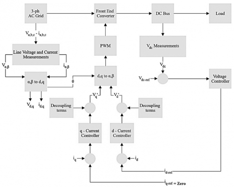
4.1 Block diagram of vector control based FEC
Numerous power electronic systems are constructed from 3-ph voltage-source converters. To generate the switching signals for the converter, the vector control method is used.
Figure 5 shows the block diagram of the proposed vector control used for FEC [34, 35]. A standard proportional-integral (PI) controller is used to run the converter in a closed-loop system. The least overshot, minimum settling time and minimal steady-state error requirements are met by PI current controllers in the d-q axis when they are developed and analyzed.
The DC-link's dynamics are then used to inform the design of a PI voltage controller that will allow the voltage control loop to function as intended [34, 35].
The principal benefits of this system include:
Figure 5. Block diagram of the proposed vector control for FEC
4.2 EV charger control
Figure 6 provides a diagrammatic representation of the control system for the EV charger. The EV is connected to the DC-Bus via a DC/DC converter, which is also known as the battery charger. In the study [36], the CC-CV charging scheme is the type of charging method that is utilized for the charging of EV batteries. In this method, the current through the battery is held steady from the beginning, while the voltage through the battery is allowed to gradually increase until it reaches a target level. This mode is known as CC. When the voltage hits this point, the current is permitted to decrease while the voltage is kept constant at the predetermined level. This mode is called CV.
The CC mode is used for most of the charging process. The DC/DC converter's switching is managed by the controller created for CC-CV charging, which also produces an output that is appropriate for an EV battery. The processor gets information about the battery's voltage and current through feedback. The MATLAB-coded CC-CV program generates voltage and current reference signals. For each operating mode, an individual P-I controller processes the error signals. The duty ratio for the DC/DC converter can be derived from the PI controller's output. This command for the duty ratio is sent to the PWM generating circuit, which in turn provides the gating signal for the switch that controls the converter [36]. The program for the CC-CV controller is depicted as a flow chart in Figure 7.
Figure 6. Scheme of a controller for EV chargers
Figure 7. Diagrammatic representation of the CC-CV controller's programming flow
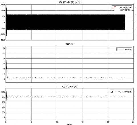
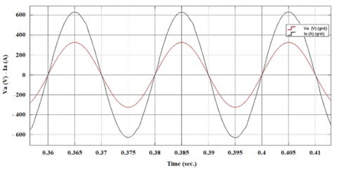
Figure 8. Shows the grid voltage and current, total harmonic distortion, and the voltage of DC-Bus
Based on Figure 2, MATLAB Simulink was used to perform the simulation investigation. The findings from the simulation are presented in the figures that follow. The waveforms for the voltage and current that are pulled from the grid by the FC station are depicted in Figures 8 and 9, respectively. The FC station draws current from all three phases of a sinusoidal input current while producing significantly less distortion.
The effectiveness of both controllers may be determined by studying the effect of THD on the injected grid current, as shown in Figure 8. The THD of the current injected into the grid is less than 1.5% for the utilized controller. THD is reduced due to the filter's design, which reduces the harmonics of the current that the inverter absorbs.
Figure 9 demonstrates that a high PF close to unity is achieved without any lag between the current and voltage of the source. Figure 8 depicts the voltage characteristic of the DC-Bus, which eventually stabilizes at the steady state value. According to the SOC graph the SOC% increased from 20% to 80% in 56.34 minutes.
Figure 9. The grid's PF is close to unity
Figure 10. EV battery's SOC characteristic, voltage, and current while it is being charged
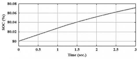
Figure 11. SOC% with respect to time in CV mode when battery SOC’s above 80%
Figure 10 depicts the SOC characteristic of the EV's battery together with the waveforms of the battery's voltage and current when the vehicle is operating in CC mode. Also demonstrates the characteristic of the battery voltage, which virtually never changes throughout this period, and the characteristic of the battery current, which almost never changes. When the battery has around 80% of its capacity left, it switches from CC mode to CV mode. The waveform of the percentage of charge remaining in the battery is depicted in Figure 11, which depicts CV mode.
In this article, a model of a FC station that can provide FC of EV is proposed. To implement a DC-Bus, an AC/DC converter is connected to the power grid. The converter was constructed in such a way that it could achieve PF operation that was very close to unity while also drawing minimal line current harmonics. When the load changes, the efficacy remains consistent. According to the findings, the $v_{d c}, V_b$, and $I_b$ all behave in a suitable dynamic manner. The proposed control method significantly lessens the occurrence of harmonics in the line current. The control is not only reasonably simple to construct, but it also provides high dynamic performance in terms of the stability of the $v_{d c}$. The charging modes can be effectively controlled using the controller created for CC-CV charging. By decreasing the net energy withdrawn from the utility, the suggested model is also beneficial in lessening the impact on the grid. The benefit that comes from having a well-coordinated electric utility operation.
In the future, rather than implementing the proposed system, subsequent work provides size reduction and efficiency improvement over implementations, which may minimize installation costs by allowing more power delivery on the same station footprint and maximize operating profit by reducing power lost in the conversion phase.
[1] Ahmad, F., Alam, M.S., Asaad, M. (2017). Developments in xEVs charging infrastructure and energy management system for smart microgrids including xEVs. Sustainable Cities and Society, 35: 552-564. https://doi.org/10.1016/j.scs.2017.09.008
[2] Amini, M.H., Boroojeni, K.G., Iyengar, S.S., Blaabjerg, F., Pardalos, P.M., Madni, A.M. (2018). A panorama of future interdependent networks: From intelligent infrastructures to smart cities. In: Amini, M., Boroojeni, K., Iyengar, S., Pardalos, P., Blaabjerg, F., Madni, A. (eds) Sustainable Interdependent Networks. Studies in Systems, Decision and Control, vol 145. Springer, Cham. https://doi.org/10.1007/978-3-319-74412-4_1
[3] El Halim, A.A.E.B.A., Bayoumi, E.H.E., El-Khattam, W., Ibrahim, A.M. (2022). Electric vehicles: A review of their components and technologies. International Journal of Power Electronics and Drive Systems, 13(4): 2041-2061. https://doi.org/10.11591/ijpeds.v13.i4.pp2041-2061
[4] Khan, W., Ahmad, A., Ahmad, F., Saad Alam, M. (2018). A comprehensive review of fast charging infrastructure for electric vehicles. Smart Science, 6(3): 256-270. https://doi.org/10.1080/23080477.2018.1437323
[5] Abd El, A.A.E.B., Nassar, Y.F., El-Khozondar, H. J., Bayoumi, E.H.E. (2023). Fast charging of lithium-ion battery for electric vehicles application. In 2023 8th International Engineering Conference on Renewable Energy & Sustainability (ieCRES), Gaza, Palestine, State of, pp. 1-6. https://doi.org/10.1109/ieCRES57315.2023.10209433
[6] Mozafar, M.R., Amini, M.H., Moradi, M.H. (2018). Innovative appraisement of smart grid operation considering large-scale integration of electric vehicles enabling V2G and G2V systems. Electric Power Systems Research, 154: 245-256. https://doi.org/10.1016/j.epsr.2017.08.024
[7] Jampeethong, P., Khomfoi, S. (2015). An EV quick charger based on CHAdeMO standard with grid-support function. In 2015 18th International Conference on Electrical Machines and Systems (ICEMS), Pattaya, Thailand, pp. 531-536. https://doi.org/10.1109/ICEMS.2015.7385092
[8] Rajagopalan, S., Maitra, A., Halliwell, J., Davis, M., Duvall, M. (2013). Fast charging: An in-depth look at market penetration, charging characteristics, and advanced technologies. In 2013 World Electric Vehicle Symposium and Exhibition (EVS27), Barcelona, Spain, pp. 1-11. https://doi.org/10.1109/EVS.2013.6914945
[9] Sahoo, J.P., Srikar, P.S.S., Sivasubramani, S. (2022). Optimal placement of plug-in hybrid electric vehicles’ parking lots in a residential distribution system. In 2022 IEEE 2nd International Conference on Sustainable Energy and Future Electric Transportation (SeFeT), Hyderabad, India, pp. 1-6. https://doi.org/10.1109/SeFeT55524.2022.9908886
[10] Silva, G.M., Pfitscher, L.L., Pauletti, P., Alves, Z.M. (2019). Recharging electric vehicles: Impact on the load curve of a low-voltage distribution network. In 2019 IEEE PES Innovative Smart Grid Technologies Conference-Latin America (ISGT Latin America), Gramado, Brazil, pp. 1-6. https://doi.org/10.1109/ISGT-LA.2019.8895307
[11] Thiringer, T., Haghbin, S. (2015). Power quality issues of a battery fast charging station for a fully-electric public transport system in Gothenburg city. Batteries, 1(1): 22-33. https://doi.org/10.3390/batteries1010022
[12] Moses, P.S., Deilami, S., Masoum, A.S., Masoum, M.A. (2010). Power quality of smart grids with plug-in electric vehicles considering battery charging profile. In 2010 IEEE PES Innovative Smart Grid Technologies Conference Europe (ISGT Europe), Gothenburg, Sweden, pp. 1-7. https://doi.org/10.1109/ISGTEUROPE.2010.5638983
[13] Pan, A., Zhu, Y., Ren, L., Chen, T., Wen, S., Yun, W. (2016). Harmonic research of electric vehicle fast chargers. In 2016 IEEE PES Asia-Pacific Power and Energy Engineering Conference (APPEEC), Xi'an, pp. 2545-2549. https://doi.org/10.1109/APPEEC.2016.7779947
[14] Lu, X., Iyer, K.L.V., Lai, C., Mukherjee, K., Kar, N.C. (2016). Design and testing of a multi-port sustainable DC fast-charging system for electric vehicles. Electric Power Components and Systems, 44(14): 1576-1587. https://doi.org/10.1080/15325008.2016.1174966
[15] Basu, M., Gaughan, K., Coyle, E. (2004). Harmonic distortion caused by EV battery chargers in the distribution systems network and its remedy. In 39th International Universities Power Engineering Conference, 2004. UPEC 2004, Bristol, UK, pp. 869-873.
[16] Duffey, C.K., Stratford, R.P. (1989). Update of harmonic standard IEEE-519: IEEE recommended practices and requirements for harmonic control in electric power systems. IEEE Transactions on Industry Applications, 25(6): 1025-1034. https://doi.org/10.1109/28.44238
[17] Khan, S., Sudhakar, K., bin Yusof, M.H. (2023). Building integrated photovoltaics powered electric vehicle charging with energy storage for residential building: Design, simulation, and assessment. Journal of Energy Storage, 63: 107050. https://doi.org/10.1016/j.est.2023.107050
[18] Simpson, M., Markel, A. (2012). Plug-in electric vehicle fast charge station operational analysis with integrated renewables (No. NREL/CP-5400-53914). National Renewable Energy Lab. (NREL), Golden, CO, USA.
[19] Joos, G., De Freige, M., Dubois, M. (2010). Design and simulation of a fast charging station for PHEV/EV batteries. In 2010 IEEE Electrical Power & Energy Conference, Halifax, NS, Canada, pp. 1-5. https://doi.org/10.1109/EPEC.2010.5697250
[20] Anastasiadis, A.G., Kondylis, G.P., Polyzakis, A., Vokas, G. (2019). Effects of increased electric vehicles into a distribution network. Energy Procedia, 157: 586-593. https://doi.org/10.1016/j.egypro.2018.11.223
[21] Galiveeti, H.R., Goswami, A.K., Choudhury, N.B.D. (2018). Impact of plug-in electric vehicles and distributed generation on reliability of distribution systems. Engineering Science and Technology, an International Journal, 21(1): 50-59. https://doi.org/10.1016/j.jestch.2018.01.005
[22] Mastoi, M.S., Zhuang, S., Munir, H.M., Haris, M., Hassan, M., Alqarni, M., Alamri, B. (2023). A study of charging-dispatch strategies and vehicle-to-grid technologies for electric vehicles in distribution networks. Energy Reports, 9: 1777-1806. https://doi.org/10.1016/j.egyr.2022.12.139
[23] Jiang, C., Torquato, R., Salles, D., Xu, W. (2013). Method to assess the power-quality impact of plug-in electric vehicles. IEEE Transactions on Power Delivery, 29(2): 958-965. https://doi.org/10.1109/TPWRD.2013.2283598
[24] Ahmad, F., Alam, M.S., Shahidehpour, M. (2017). Optimal placement of electric, hybrid and plug-in hybrid electric vehicles (xEVs) in Indian power market. In 2017 Saudi Arabia Smart Grid (SASG), Jeddah, Saudi Arabia, pp. 1-7. https://doi.org/10.1109/SASG.2017.8356502
[25] Secchi, M., Barchi, G., Macii, D., Petri, D. (2023). Smart electric vehicles charging with centralised vehicle-to-grid capability for net-load variance minimisation under increasing EV and PV penetration levels. Sustainable Energy, Grids and Networks, 35: 101120. https://doi.org/10.1016/j.segan.2023.101120
[26] Zhao, H., Burke, A. (2014). An intelligent solar powered battery buffered EV charging station with solar electricity forecasting and EV charging load projection functions. In 2014 IEEE International Electric Vehicle Conference (IEVC), Florence, Italy, pp. 1-7. https://doi.org/10.1109/IEVC.2014.7056169
[27] Negarestani, S., Fotuhi-Firuzabad, M., Rastegar, M., Rajabi-Ghahnavieh, A. (2016). Optimal sizing of storage system in a fast charging station for plug-in hybrid electric vehicles. IEEE Transactions on Transportation Electrification, 2(4): 443-453. https://doi.org/10.1109/TTE.2016.2559165
[28] Funke, S., Jochem, P., Ried, S., Gnann, T. (2020). Fast charging stations with stationary batteries: A techno-economic comparison of fast charging along highways and in cities. Transportation Research Procedia, 48: 3832-3849. https://doi.org/10.1016/j.trpro.2020.08.036
[29] Dragičević, T., Sučić, S., Vasquez, J.C., Guerrero, J.M. (2014). Flywheel-based distributed bus signalling strategy for the public fast charging station. IEEE Transactions on Smart Grid, 5(6): 2825-2835. https://doi.org/10.1109/TSG.2014.2325963
[30] Abo-Khalil, A.G., Abdelkareem, M.A., Sayed, E.T., Maghrabie, H.M., Radwan, A., Rezk, H., Olabi, A.G. (2022). Electric vehicle impact on energy industry, policy, technical barriers, and power systems. International Journal of Thermofluids, 13: 100134. https://doi.org/10.1016/j.ijft.2022.100134
[31] Madhav, G., Ramakrishna, K. (2018). A novel fast energy based fuzzy logic DC-link voltage controller for three phase DSTATCOM to compensate AC loads. International Journal of Pure and Applied Mathematics, 118(24).
[32] Singh, S.N. (2017). Selection of non-isolated DC-DC converters for solar photovoltaic system. Renewable and Sustainable Energy Reviews, 76: 1230-1247. https://doi.org/10.1016/j.rser.2017.03.130
[33] Taghvaee, M.H., Radzi, M.A.M., Moosavain, S.M., Hizam, H., Marhaban, M.H. (2013). A current and future study on non-isolated DC–DC converters for photovoltaic applications. Renewable and Sustainable Energy Reviews, 17: 216-227. https://doi.org/10.1016/j.rser.2012.09.023
[34] Bayoumi, E.H.E. (2004). Analysis and design of linear and variable structure control techniques for PWM rectifier. Electromotion Scientific Journal, 11(4): 205-212.
[35] Hamed, H.A., Abdou, A.F., Bayoumi, E.H., El-Kholy, E.E. (2015). New current references calculation for dual vector controlled three level active rectifiers under asymmetrical voltage operation. International Journal of Industrial Electronics and Drives, 2(4): 251-261. https://doi.org/10.1504/IJIED.2015.076295
[36] Abd El, A.A.E.B., Bayoumi, E.H.E., El-Khattam, W., Ibrahim, A.M. (2023). Effect of fast charging on lithium-ion batteries: A review. SAE International Journal of Electrified Vehicles, 12(3): 361-388. https://doi.org/10.4271/14-12-03-0018