Muhammed A. Ibrahim*![]() | Ahmed Nasser B. Alsammak
| Ahmed Nasser B. Alsammak![]()
© 2023 IIETA. This article is published by IIETA and is licensed under the CC BY 4.0 license (http://creativecommons.org/licenses/by/4.0/).
OPEN ACCESS
The rising demand for clean and abundant energy sources has guided growing interest in transportation electrification. Recently, a broad interest in electric vehicles (EVs) and their development has begun due to oil depletion, price rise, and the air pollution produced by cars with internal combustion engines (ICE). Therefore, the researchers are motivated to seek alternative energy sources to propel the car. Nowadays, switched reluctance motor (SRM) is gaining more and more attention in recent high-speed industrial applications. The researcher’s trend has moved towards developing more environmentally friendly systems. This study aims to improve the SRM drive system to achieve reliability and torque quality. It proposes a rapid optimization-based bacterial foraging procedure for selecting the optimum value commutation angles. Quality indicators like torque ripple measure motor performance in terms of acoustic noise and mechanical vibration. The percentage of torque ripple is employed as a metric to assess the quality of SRM drive torque. The results indicate that minimizing torque fluctuations in an SRM motor is feasible by selecting an appropriate commutation angle through optimization.
switched reluctance motor (SRM), commutation angles control, torque ripple, bacterial foraging algorithm
An electric motor is a crucial EV component. It converts electrical energy into mechanical energy to drive the wheels of the vehicle. Research activities relating to advanced traction motors primarily focus on specifications. Torque quality is essential for the optimal traction of electric machines in the industry. The major drawback of typical SRM is that it has significant torque ripples and is difficult to control. However, the rugged, simple, and low-cost construction of SRM makes it a viable long-term applicant for electrified transportation. Developed design and control methods can reduce percentage torque ripples, vibration, and noise in SRM [1, 2]. Various factors, including the commutation angle, influence torque quality in an SRM. The commutation angle refers to the angle at which the current in one phase is switched off while the current in the next phase is switched on to maintain continuous motor rotation. Proper commutation is essential to achieve smooth and efficient motor operation.
Numerous approaches have been employed in recent years to mitigate torque ripple, including control techniques that rely on pulse waveforms and optimum excitation angles. In reference [3], the authors proposed an automated method for controlling the turn-on angle. The objective of this method was to enhance the torque per ampere, while maintaining a constant conduction angle. In this study, an algorithm for determining the turn-on angle is proposed, with the objective of maximizing the average torque. Additionally, a closed-loop controller is employed to facilitate the acquisition of the optimal turn-on angle. In reference [4], examined the optimal current required to achieve maximum torque per ampere by employing the field reconstruction method (FRM). The technique under consideration has been implemented at different velocities, and the outcome of the simulation or experiment has been observed. According to the FRM framework, an iterative optimization technique is proposed. This technique determines the optimal commutation angles for reference torque and speed. This method has effectively enhanced the torque per ampere (TPA), as evidenced by both simulation and experimental findings. A new power converter for SRM drives that reduces switching losses, particularly at low speeds, and eliminates source energy intake during the energy discharge process. It increases the efficiency of the drive across the entire range of rotational speed. It presents a computer-based model of the drive and a comprehensive analysis of the relationship between output power and rotational speed for a sample two-phase motor-based drive. The paper concludes that the proposed C-dump converter with 2q (q number of phase) transistors has higher maximum power than the C-dump converter with a single transistor [5]. The reference [6] compared three candidate motor topologies for traction applications in electric and hybrid vehicles. The topologies studied interior permanent magnet synchronous motor (IPMSM), induction motor (IM), and SRM. The paper presents a fast FEA modelling approach for IM design and optimal current trajectories for IPMSMs and IM to achieve high motor efficiency. Additionally, optimal commutation angles with current chopping control (CCC) and angular position control (APC) are established for SRM. The simulation and analytical consequences demonstrate that each motor topology for EVs and hybrid electric vehicle (HEVs) possesses a unique characteristic. Currently, two widely employed strategies for achieving smooth torque control in SRMs are direct instantaneous torque control (DITC) and direct torque control (DTC). The mechanism of DTC is intricate as it involves individual control of torque for each phase [7, 8].
This paper aims to establish the fundamental principles of the minimum percentage torque ripple methodology across various speeds, employing the bacterial foraging optimization algorithm (BFOA). The present study systematically varies the turn-on and turn-off angles across their respective ranges. To enhance the quality of the torque produced by the 8/6 SRM drive system.
The assessment of SRM drive performance is a complex endeavour due to the many parameters implicated. The interconnections between motor design and switching circuits as well as the influence of machine parameters on current and rotor position. A fundamental requirement for developing an accurate model is a thorough comprehension of the parameters associated with the SRM and their interdependencies with control and converter operations. It is imperative to employ a system model that accurately reflects real-world conditions to assess the efficacy of novel control strategies and evaluate the effectiveness of new designs or enhancements. A high-fidelity model should be able to accurately forecast for the drive system’s performance across a broad spectrum of torque and speed variations [9, 10].
The electrical and mechanical models of the SRM are presented to express the machine’s dynamic behaviour. Certain variables’ dependence on the rotor position and the magnetic saturation are also considered. In SRM, the voltage equation is given by the studies [9, 11]:
$v=R \times i+d \lambda / d t$ (1)
where, R represents the resistance of the stator windings and λ represents the flux linkage. Magnetic saturation can be considered because the flux linkage is now a function of the current and the rotor position (Ө). Therefore, the concept of flux linkage can be precisely characterized as:
$\lambda(i, \theta)=L(i, \theta) \times i(t)$ (2)
where, L is the machine inductance.
Substituting Eq. (2) in Eq. (1) and calculating its derivative results in:
$v=R \times i+L(i, \theta) \frac{d i}{d t}+i \frac{d L(\theta, i)}{d t}$ (3)
The expansion of the derivative of the inductance concerning time is obtained by performing a mathematical operation to express the derivative in a more detailed form:
$\frac{d L(\theta, i)}{d t}=\frac{\partial L(\theta, i)}{\partial \theta} \frac{d \theta}{d t}+\frac{\partial L(\theta, i)}{\partial i} \frac{d i}{d t}$ (4)
By substituting (4) in (3) and rearranging the terms, we can obtain:
$v=R \times i+l(i, \theta) \frac{d i}{d t}+E$ (5)
where,
$l(\theta, i)=L(i, \theta) \frac{d i}{d t}+i \frac{\partial L(\theta, i)}{\partial i}$ (6)
$£=i w_m \frac{\partial L(\theta, i)}{\partial \theta}$ (7)
$w_m=\frac{d \theta}{d t}$ (8)
The first term $l(\theta, i)$ refers to incremental inductance [11]. It considers current, self-inductance $L(i, \theta)$, and inductance variation due to current to account for the effects of magnetic saturation. The £ symbol stands for the back-emf of the machine [12].
Thus, the electromagnetic torque value (Te) can be determined for a given current value by the rate of change of co-energy to position, as seen in the Eq. (9).
$T_e=\frac{d L(\theta, i)}{\Delta \theta} \frac{i^2}{2}$ (9)
The equation of motion governs the mechanical dynamics of both the motor and the load. Regarding the functioning of a motor, the dynamic equation of a rotating machine can be established as follows [10]:
$\frac{d}{d t} w_m=-\frac{B}{J} w_m+\frac{1}{J} T_m$ (10)
The friction coefficient is denoted as B, while the rotor moment of inertia is represented by J. The concept of mechanical torque can be defined as:
$T_m=T_e+T_L$ (11)
The variable $T_L$ represents the load torque exerted on the shaft of the machine.
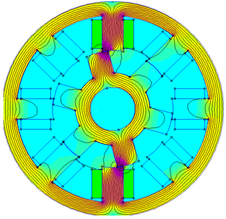
The SRM utilized in this study is a classical 4-phase 8/6 machine [12, 13]. The non-linear properties of the machine are derived through a sequence of static two-dimensional finite element analyses based on the FEMM 4.2 program [14]. After solving for machine parameters, the values are readily available in the results part of FEMM software. The flux lines in the investigated SRMs at three distinct positions (unaligned, misaligned and aligned) can be viewed in Figures 1, 2 and 3, respectively. The significance of these positions lies in giving an overall non-linearity to this type of machine. Non-linear variation in inductance is caused by the fringe flux, which is more pronounced in the misaligned and intermediate positions.
Figure 1. Distribution and density of magnetic flux in the 8/6 SRM for unaligned rotor position: 16A, rotor position=30º
Figure 2. Distribution and density of magnetic flux in the 8/6 SRM for aligned rotor position: 16A, rotor position=0º
Figure 3. Distribution and density of magnetic flux in the 8/6 SRM for aligned rotor position: 16A, rotor position=15º
The Flux-Current-Position characteristics are displayed in Figure 4, while the Torque-Current-Position characteristics are presented in Figure 5.
With the obtained (λ-i-θ) characteristics and (T-i-θ) characteristics and using Eqs. (1) to (12). The non-linear SRM simulation is built based on the current I (λ, θ) and the torque T (θ, i) look-up tables. The implementation of the SRM is carried out utilizing the MATLAB/Simulink® software.
Figure 4. Flux – Current – Position characteristics (λ-i-θ characteristics)
Figure 5. Torque – Current – Positions characteristics (T-i-θ characteristics)
In contrast to most electric machines, the SRM exhibits two additional degrees of freedom, namely, its commutation angles, when operating below its base speed. The performance of the drive is directly influenced by the selection of various angles under a specific speed and load condition. Increasing the duration of the excitation interval has the potential to mitigate torque ripple. A shorter interval can minimize copper and iron losses, among other benefits. Moreover, the parameters are influenced by both speed and load, necessitating a comprehensive profile to be established [15].
The optimization of SRM control variables goals to attain optimal performance for the SRM drive system at different operating points. A proposed optimization methodology employing a multidimensional approach utilizing simulation techniques has been put forth to enhance the performance of the SRM across a broad range of speeds. Commutation angle optimization in an SRM involves finding the most suitable commutation angles for the motor’s phases to achieve desired performance characteristics such as reduced torque ripple, increased efficiency, and improved overall operation. In order to enhance the conduction angles, it is imperative to employ a model that can effectively compute the dynamic torque profile of the machine based on the provided conduction angles. The torque quality formulation in SRM drive is given as follows [16]:
The instantaneous electromagnetic torque $T_{\text {inst }}$:
$T_{inst} \sum_0^q T_e(I p, \theta)$ (12)
Average torque $T_{a v g}$:
$T_{avg}=\frac{1}{\delta} \int_0^\delta T_{\text {inst }}(t) d t$ (13)
Maximum torque $T_{max}$:
$T_{m a x}=\operatorname{Max}(Tinst)$ (14)
Minimum torque $T_{min}$:
$T_{min}=\operatorname{Min}(Tinst)$ (15)
Torque pulsation $T_{p p}$:
$T_{p p}=T_{\max }-T_{\min }$ (16)
Percentage torque ripple $T_r$:
$T_r=\frac{T m a x-T m i n}{T_{\text {avg }}}$ (17)
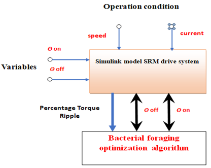
The minimum percentage torque ripple criteria performance index in an SRM drive system aims to optimize the motor for achieving a minimum level of torque ripple. Torque ripple refers to the variation in torque output during the motor’s operation, which can negatively impact the motor’s performance, efficiency, and smoothness of operation. The percentage torque ripple measures the magnitude of torque ripple relative to the average torque output. Minimizing the percentage torque ripple allows the motor to operate with reduced torque fluctuations, resulting in smoother operation, improved performance, and reduced noise and vibration levels. Figure 6 presents the formalization of the performance index selection process based on BFOA [17, 18]. We have employed BFOA to ascertain the optimal commutation angles of an SRM. Owing to its simplicity, ease of implementation, and high effectiveness, BFOA can deliver high-quality solutions, improving transient and steady-state performances [2, 19].
Figure 6. Description of the optimization problem
This investigation focuses on implementing a partition that follows the proposed SRM drive system, specifically optimizing the commutation angles of the intended SRM. The MATLAB/SIMULINK software is utilized for this purpose. The investigation focuses on analyzing the system’s responses in various operating scenarios.
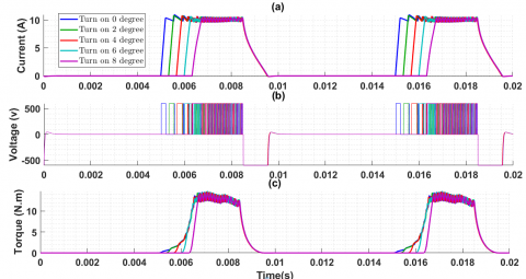
The characteristics analysis is achieved based on the simulation platform. Figure 7 presents the electromagnetic torque and phase “a” current and voltage waveforms for a speed of 1000rpm and Iref=10A at five different values of turn-on angle are considered (0º, 2º, 4º, 6º, 8º), while the turn-off angle is kept constant at 21º.
Figure 7. Simulation results for different values of $\theta_{o n}$ with $\theta_{\text {off }}=21^{\circ}$, at a speed of $1000 \mathrm{rpm} . I_{r e f}=10A$ (a) Phase 'a' current. (b) Phase 'a' Voltage (c) Phase 'a' electromagnetic torque
To obtain a clear physical insight into the turn-on angle impact on the selected performance index quantities such as maximum torque, minimum torque, average torque, torque ripple, and percentage torque ripple, The simulation data of all the cases as mentioned above are stated in Table 1.
Table 1. Effect of turn-on ($\theta_{o n}$) angle variation on performance indexes at speed 1000rpm and $I_{r e f}$ 10A
|
Commutation Angle (degree) |
Tmin (N.m) |
Tmax (N.m) |
Tp-p (N.m) |
Tavg (N.m) |
Tr(%) |
|
θon=0 |
8.77 |
14.73 |
5.96 |
12.87 |
46.31 |
|
θoff=21 |
|||||
|
θon=2 |
8.65 |
15.06 |
6.41 |
2.69 |
50.53 |
|
θoff=21 |
|||||
|
θon=4 |
8.49 |
14.82 |
6.33 |
12.6 |
50.23 |
|
θoff=21 |
|||||
|
θon=6 |
4.47 |
14.71 |
7.24 |
12.33 |
58.69 |
|
θoff=21 |
|||||
|
θon=8 |
2.77 |
14.49 |
11.73 |
11.01 |
106.51 |
|
θoff=21 |
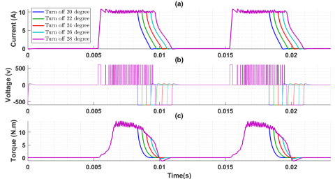
Figure 8 presents the electromagnetic torque and phase “a” current and voltage waveforms for a speed of 500rpm and Iref=10A at Five different values of θ off are considered (20º, 22º, 24º, 26º, 28º), while θ on is kept constant at 2º.
In order to gain a comprehensive understanding of the influence of the turn-off angle on various performance indices, including maximum torque, minimum torque, average torque, torque ripple, and percentage torque ripple, the simulation results for all the selected operating point above is presented in Table 2.
The result shows that the duration for which the phase current is permitted to increase or decrease depends on various factors, including the speed of the motor, the magnitude of the current, as well as the angles θon and θoff There is a significant disparity in the motor current profile for low, medium and high-speed operations.
The optimized commutation angle at a speed of 1000rpm for different current values for minimum percentage torque ripple is presented in Table 3 by applying the proposed BFOA optimization algorithm in Figure 6.
The consequences of the simulation platform have been obtainable. The outcomes above are utilized to ascertain the effectiveness and reliability of the commutation angles control utilizing BFOA for the SRM drive system. A simulation is accomplished to observe the correlation between the torque quality and commutation angles.
Figure 8. Simulation results for different values of θoff with θon =2º, at a speed of 1000rpm and Iref=10A. (a) Phase 'a' current (b) phase 'a' voltage (c) phase 'a' electromagnetic torque
Table 2. Effect of turn-off (θoff) angle variation on performance indexes at speed 1000rpm and Iref=10A
|
Commutation Angle (degree) |
Tmin (N.m) |
Tmax (N.m) |
Tp-p (N.m) |
Tavg (N.m) |
Tr(%) |
|
θon=2 |
6.45 |
14.49 |
8.04 |
11.9 |
67.59 |
|
θoff=20 |
|||||
|
θon=2 |
11.27 |
15.77 |
4.49 |
13.45 |
33.4 |
|
θoff=22 |
|||||
|
θon=2 |
11.86 |
20.53 |
8.67 |
14.81 |
58.55 |
|
θoff=24 |
|||||
|
θon=2 |
11.6 |
23.05 |
11.45 |
15.68 |
73.03 |
|
θoff =26 |
|||||
|
θon=2 |
10.62 |
23.05 |
12.43 |
15.96 |
77.91 |
|
θoff =28 |
Table 3. Optimized commutation angle at a speed of 1000rpm for minimum percentage torque ripple criteria
|
Reference Current |
Optimal Commutation Angle (degree) |
Tmin (N.m) |
Tmax (N.m) |
Tp-p (N.m) |
Tavg (N.m) |
Tr(%) |
|
16A |
θon =0.230 |
24.92 |
30.96 |
6.04 |
27.72 |
21.78 |
|
θoff =22.28 |
||||||
|
14A |
θon =0.735 |
20.32 |
25.33 |
5.01 |
22.89 |
21.89 |
|
θoff =22.17 |
||||||
|
12A |
θon =0.094 |
16.13 |
20.47 |
4.34 |
18.43 |
23.54 |
|
θoff =22.40 |
||||||
|
10A |
θon =0.365 |
12.13 |
15.70 |
3.57 |
13.78 |
25.89 |
|
θoff =22.15 |
||||||
|
8A |
θon =2.166 |
7.85 |
10.64 |
2.79 |
9.14 |
30.15 |
This study aimed to ascertain the optimal commutation angles for minimizing the percentage torque ripple in a four-phase 8/6 SRM drive system. In the MATLAB/Simulink environment, a precise non-linear model of an SRM is developed, along with a technique for optimizing commutation angles to minimize the percentage of torque ripple. Additionally, a method for minimizing the percentage of torque ripple through adaptive commutation angles based on the BFOA is intended. The turn-on and turn-off angles are dynamically modified to enhance the commutation period. The simulation results demonstrate that the proposed optimization strategy for commutation angles is highly efficient in minimizing the percentage torque ripple, as indicated in Table 3. The method proposed in this study is straightforward to implement, requiring no complicated algorithmic structure. It is suggested in the future research directions for the SRM drive control integrate torque and power quality into a multi-objective optimization strategy.
The authors are grateful to (The University of Mosul / College of Engineering) for their provided facilities, which helped to enhance the quality of this work.
[1] Bilgin, B., Emadi, A. (2014). Electric motors in electrified transportation: A step toward achieving a sustainable and highly efficient transportation system. IEEE Power Electronics Magazine, 1(2): 10–17. https://doi.org/10.1109/mpel.2014.2312275
[2] Alhattab, A.S., Alsammak, A.N.B., Mohammed, H.A. (2023). An intelligent mitigation of disturbances in electrical power system using distribution static synchronous compensator. Indonesian Journal of Electrical Engineering and Computer Science, 30(2): 633-642. https://doi.org/10.11591/ijeecs.v30.i2.pp633-642
[3] Sozer, Y., Torrey, D.A., Mese, E. (2003). Automatic control of excitation parameters for switched-reluctance motor drives. IEEE Transactions on Power Electronics, 18(2): 594–603. https://doi.org/10.1109/tpel.2003.809352
[4] Lin, C., Fahimi, B. Optimization of commutation angles in SRM drives using FRM. In 2012 IEEE Transportation Electrification Conference and Expo (ITEC), Dearborn, MI, USA, pp. 1-6. https://doi.org/10.1109/itec.2012.6243493
[5] Tomczewski, K., Wrobel, K. (2014). Improved C-dump converter for switched reluctance motor drives. IET Power Electronics, 7(10): 2628-2635. https://doi.org/10.1049/iet-pel.2013.0738
[6] Yang, Z., Shang, F., Brown, I.P., Krishnamurthy, M. (2015). Comparative study of interior permanent magnet, induction, and switched reluctance motor drives for EV and HEV applications. IEEE Transactions on Transportation Electrification, 1(3): 245-254. https://doi.org/10.1109/tte.2015.2470092
[7] Jeyabharath, R., Veena, P., Rajaram, M. (2006). A novel DTC strategy of torque and flux control for switched reluctance motor drive. In 2006 International Conference on Power Electronic, Drives and Energy Systems, New Delhi, India, pp. 1-5. https://doi.org/10.1109/pedes.2006.344359
[8] Foo, G.H.B., Zhang, X. (2016). Robust constant switching frequency-based field-weakening algorithm for direct torque controlled reluctance synchronous motors. IEEE Transactions on Industrial Informatics, 12(4): 1462-1473. https://doi.org/10.1109/tii.2016.2585646
[9] Krishnan, R. (2017). Switched Reluctance Motor Drives. CRC Press, Boca Raton, USA.
[10] Ibrahim, M.A., Alsammak, A.N.B. (2022). Switched reluctance motor drives speed control using optimized PID controller. Przeglad Elektrotechniczny, 98(11): 46-50. https://doi.org/10.15199/48.2022.11.07
[11] Fang, G., Scalcon, F.P., Xiao, D., Vieira, R.P., Gründling, H.A., Emadi, A. (2021). Advanced control of switched reluctance motors (SRMs): A review on current regulation, torque control and vibration suppression. IEEE Open Journal of the Industrial Electronics Society, 2: 280-301. https://doi.org/10.1109/ojies.2021.3076807
[12] Roy, D., Sengupta, M. (2019). A novel and precise on-line digital measurement of unsaturated phase inductance of a switched reluctance motor. Sādhanā, 44(11): 221. https://doi.org/10.1007/s12046-019-1195-9
[13] Hamouda, M., Számel, L. (2019). Accurate magnetic characterization based model development for switched reluctance machine. Periodica Polytechnica Electrical Engineering and Computer Science, 63(3): 202-212. https://doi.org/10.3311/ppee.14012
[14] Meeker, D. (2010). Finite element method magnetics. https://www.femm.info, accessed on 11 Jan, 2020.
[15] Mademlis, C., Kioskeridis, I. (2003). Performance optimization in switched reluctance motor drives with online commutation angle control. IEEE Transactions on Energy Conversion, 18(3): 448-457. https://doi.org/10.1109/tec.2003.815854
[16] Bizkevelci, E., Ertan, H.B., Leblebicioglu, K. (2007). Effects of control parameters on SRM performance: A parametric search. In 2007 International Aegean Conference on Electrical Machines and Power Electronics, Bodrum, Turkey, pp. 276-281. https://doi.org/10.1109/acemp.2007.4510517
[17] Passino, K.M. (2005). Biomimicry for Optimization, Control, and Automation. Springer Science & Business Media, London.
[18] Bermejo, E., Cordón, O., Damas, S., Santamaría, J. (2015). A comparative study on the application of advanced bacterial foraging models to image registration. Information Sciences, 295: 160-181. https://doi.org/10.1016/j.ins.2014.10.018
[19] Akkara, S., Jarin, T. (2022). PI controller based switching reluctance motor drives using smart bacterial foraging algorithm. EAI Endorsed Transactions on AI and Robotics, 1(1). http://doi.org/10.4108/airo.v1i.15