Wael A. H. Hadi![]() | Amjad Ali Jassem
| Amjad Ali Jassem![]() | Atheer A. Sabri
| Atheer A. Sabri![]() | Riyam S. Ali*
| Riyam S. Ali*![]()
© 2023 IIETA. This article is published by IIETA and is licensed under the CC BY 4.0 license (http://creativecommons.org/licenses/by/4.0/).
OPEN ACCESS
This paper introduces a novel pseudo-random sequence generator, applicable across all uses of pseudo noise (PN)-sequence. The proposed generator, coined as the circular pseudo-random signal generator, embodies a unique fusion of graphical representation and mathematical modeling. The cornerstone of this method is its capability to offer variable configurations in pseudo-random sequence generation, enabling the adaptive operation of the pseudo-random sequence between the transmitter and the receiver. Uniquely, the circular pseudo-random sequence generator can generate pseudo-random sequences of varying lengths, with practical implementation feasible through multiple methodologies, including microcontrollers or field-programmable gate array (FPGA) technology. Consequently, the paper endeavors to elucidate the mathematical model of generation, supplemented with illustrative examples, and demonstrate the real-world implementation using FPGA technology. With broad applicability, this sequence generator is well-suited to all applications requiring such a generator, notably in security applications and pilot generations.
adaptive, random sequence, circular, FPGA, linear feedback shift register (LFSR)
The circular sequence generator was introduced to provide a dynamic random sequence generator. What is meant by dynamic? Let's Consider two communication points: one represents the transmitter, and the second is the receiver side. Consider there is a need for changing the sequence as a security application. But the hardware of the equipment is fixed indeed. What can we do in such a situation? The circular sequence generator gives a software solution by changing only the generation key. This key is shared between the transmitter and receiver or between one and multiple receivers. The hardware is designed according to the circles representing the generator's structure. These circles can give multiple different PN sequences according to the KEY. This scenario gives a solution for changing the PN sequence. This paper introduces the concept of the generation and the KEY. The designer can construct multiple circles with multiple levels and KEY as accepted between the transmitter and the receiver. Random sequence frames are frequently employed in numerous applications, including security software and modern communication networks. Thus, random sequence generation fields subsequently attracted many researchers for many years. Such research seeks to develop random sequence generation.
For example, one of the most commonly used methods for generating a pseudo-random sequence is a linear feedback shift register (LFSR). To generate the random series, a group of shift registers connected in serial is used [1]. This low-complexity approach (LFSR) is implemented with straightforward shift registers or by employing FPGA technology. To be used in applications related to security, random number generation (RNG) is introduced [2]. For data ciphering in cryptography, there is an absolute requirement for a random sequence with a respectable unpredictability probability.
There, the function of mathematics in creating random sequences becomes apparent. Many researchers organize competitions to create a sequence with the highest probability of randomness [2]. Using a Gaussian random number generator (GRNG) technique, for instance, to generate a random number series and analyze how those numbers behave in the vicinity of the Gaussian probability density function (GPDF) [3]. Additionally, pseudo-random sequence generations find their way into database applications; it introduces a generation algorithm with SQL 2000 database application [4]. Furthermore, accumulator recursions with time variation produce the random sequence.
Given that it employs a small amount of hardware, this method is characterized by a lower level of complexity [5]. In communication applications, the generation of random sequences is widely employed. Audio can produce sequences with an acceptable probability of randomization [6]. Quadratic irrationals are also used in pseudo-random number generation to create a generator that must be incorporated into encryption [6]. Due to their versatility in hardware configuration and speed, the FPGA architecture is used to construct the random sequence generator [7]. In modern cipher systems like the rabbit cipher, the random sequence serves the security application efficiently [8]. Computer-generated pseudo-random sequences may have problems with good randomized start points, while the remaining random sequence has deterministic or parodic characteristics.
Unlike conventional random number generators, quantum number generation has been established to produce random numbers [9]. The chaotic subject combined with random number generators. The chaotic system is also used to generate the random number sequence used with security applications [10]. New fundamentals and design concepts for a pseudo-random number generator (PRNG) are also made possible by the expansion of chaotic neural network structures [11]; however, specific possible information security issues are raising concerns [12]. To enhance its statistical features, a random generator based on the logistic map is utilized, and its chaotic parameter is dynamically changed; 510 lookup tables (LUTs) and 120 registers were used to implement the system in a Virtex 7 FPGA [13, 14]. This research paper uses a random pattern as the adaptive sequence between the sender and the recipient in a communication system.
The significant points covered within the circular pseudo-random sequence generator are designed as follows:
(1) The mathematical model of the proposed method is designed to be practically implemented.
(2) The mathematical model allows for modifying the generated sequence according to an understanding between the transmitter and the receiver. As a result, it offers an adaptive process and generates a unique pseudo-random sequence for every modification of the mathematical model component.
(3) The circular pseudo sequence generator also provides some variables in terms of the length based on the presetting mathematical model parameter.
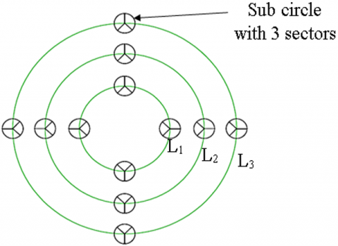
Illustrate the mathematical model of the circular random sequence generator. The circular generator should be considered a circle called level, and the level circle is the big circle shown in green color. This level circle includes several circles within its circumference, small circles called sub-circles shown in black color; each sub-circle is divided into multiple parts called sectors. Each sector represents a specific digit. Thus, the key could be in the form as long as it is included as a mathematical representation of this circle, as it is shown in Eq. (1):
Key={ci, n, R, D} (1)
where, ci is the number of sub-circles, the key can include more than a single sub-circle. The number of sectors for the circumference sub-circle is n, R is the number of rotations, and D is the direction of rotation if we consider the following:
Each rotation gives a random set of binary sequences equal to:
Set length/rotation=no. of sub circles (c)×no. of layers (L) (2)
where, L is the number of layers. If each sub-circle gives a single bit at each rotation, the maximum number of rotations permitted is equal to the number of sectors of sub-circles, as shown in Figure 1:
Rmax maximum rotations=n (3)
Maximum frame length=Rmax×n×L (4)
Figure 1. Circular pseudo-random sequence generator graphical representation. Three layers, 12 sub-circles with three sectors
To discuss the circular operation, let's consider the following illustrative examples:
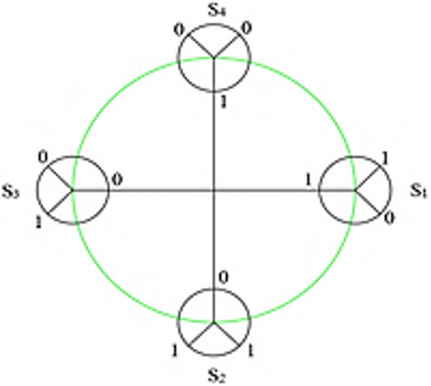
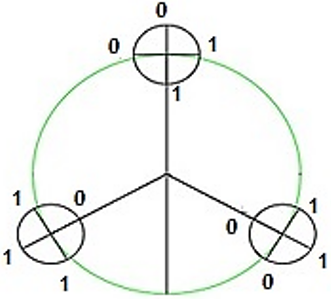
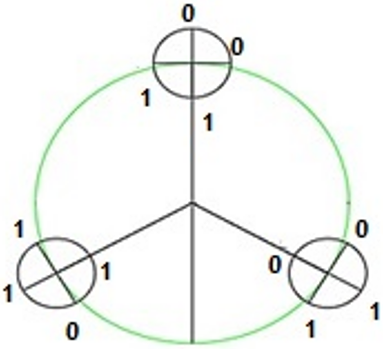
Example 1: Consider the Key={ci, ni, Ri, D}={4, 3, 2, 0}, first circle at location 0, with sectors: S1={1, 0, 1}, S2={1, 1, 0}, S3={1, 0, 0} and S4={0, 0, 1}, as shown in Figure 2 and Figure 3. Read the sequence from the inner axis starting from the first axis on the right.
The first sequence generated F1={1, 1, 1, 0}.
The second sequence generated F2={1, 0, 0, 1}.
For two rotations: Pseudo random sequence={F1, F2}.
Pseudorandom sequence={1, 1, 1, 0, 1, 0, 0, 1}.
Figure 2. Key={4, 3, 2} at first rotation R=1 clockwise
Figure 3. Key={4, 3, 2} at second rotation R=2 clockwise
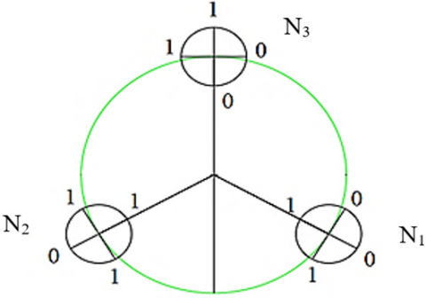
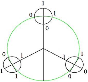
Example 2: Consider the key={ci, ni, Ri, D}={3, 4, 2, 0}, find generated frame and Rmax, with following sectors: N1={1, 0, 0, 1}, N2={1, 1, 0, 1} and N3={0, 1, 1, 0}, as shown in Figures 4, 5, 6 and 7 respectively.
F1={1, 1, 0}, F2={1, 1, 0}.
Frames={F1, F2}={1, 1, 0, 1, 1, 0}.
Rmax=4, there are four rotations to complete all pseudo-random frames.
Maximum frame length=Rmax×ci=4×3=12.
Fmax={F1, F2, F3, F4}={1, 1, 0, 1, 1, 0, 0, 0, 1, 0, 1, 1}.
Figure 4. Key={3, 4, 2, 0} at first rotation R=1 clockwise, F1={1, 1, 0}
Figure 5. Key={3, 4, 2, 0} at second rotation R=2 clockwise, F2={1, 1, 0}
Figure 6. Key={3, 4, 2, 0} at Third rotation R=3 clockwise, F3={0, 0, 1}
Figure 7. Key={3, 4, 2, 0} at fourth rotation R=4 clockwise, F4={0, 1, 1}
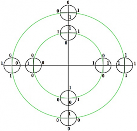
Example 3: For multiple layer circular random sequence generator, consider the general form: K={ci, ni, Ri, Di}, where the last Di represents rotation direction, 1 for clockwise and 0 represents Anti-clockwise, K1={4, 4, 2, 0} and K2={4, 4, 2, 1}.
K1 sectors: Anti-clockwise
N1={1,0,1,0}, N2={1,1,0,0}, N3={0,0,1,0}, N4={0,1,1,1}.
K2 sectors: Clockwise
N1={1,1,1,1}, N2={1,0,0,0}, N3={0,1,1,0}, N4={1,0,0,1}.
The graphical representation for the circular sequence generator will be as shown in Figure 8:
Figure 8. K1={4, 4, 2, 0}, K2={4, 4, 2, 1}
Denote the frame as F(Ri, L), where F represents the frame per Ri, the rotation, and L is the level.
F(1, 1)={1, 1, 0, 0} First rotation from level L=1, Clockwise.
F(1, 2)={1, 0, 0, 1} First rotation from level L=2, Anti-clockwise.
F(2, 1)={0, 1, 0, 1} Second rotation from level L=1, Clockwise.
F(2, 2)={1, 0, 1, 1} Second rotation from level L=2, Anti-clockwise.
Resulted frame F={F(1, 1), F(1, 2), F(2, 1), F(2, 2)},
F={1, 1, 0, 0, 1, 0, 0, 1, 0, 1, 0, 1, 1, 0, 1, 1}.
If we consider Rmax=n=4,
The max frame length=Rmax.c1+Rmax.c2.
Then, for multiple layers L:
Max. frame length=$\sum_{i=1}^L$Rmax.ci, and frame length=$\sum_{i=1}^L$R.ci, where Rmax here related to the number of sectors/layer.
For example, 3:
n(1, 1)=4, n(1, 2)=4 then Rmax = 4.
Frame length=4×c1+4×c2= 4×4+4×4=16+16=32.
But with consider K1=clockwise, K2=anti-clockwise.
$\left.\begin{array}{l}\mathrm{F}_{(1,1)}=\{1,1,0,0\} \\ \mathrm{F}_{(2,1)}=\{0,1,0,1\} \\ \mathrm{F}_{(3,1)}=\{1,0,1,1\} \\ \mathrm{F}_{(4,1)}=\{0,0,0,1\}\end{array}\right\}$ Anti-clockwise
$\left.\begin{array}{l}\mathrm{F}_{(1,2)}=\{1,0,0,1\} \\ \mathrm{F}_{(2,2)}=\{1,0,1,1\} \\ \mathrm{F}_{(3,2)}=\{1,0,1,0\} \\ \mathrm{F}_{(4,2)}=\{1,1,0,1\}\end{array}\right\} $ Clockwise
Frame={F(1,1), F(1,2), F(2,1), F(2,2), F(3,1), F(3,2), F(4,1), F(4,2)}.
Frame={F(1,L=1), F(1,L=2), …, F(Rmax, Li)}.
Simulation of the mathematical model of the circular pseudo-random sequence generator performed in MATLAB. The complete code describing the mathematical model and sequence generation was successfully implemented. The following MATLAB code exhibits a run and test for the first example. The MATLAB m file script is as follows:
Call the function:
K1=[4, 4, 2, 0] % set the key parameter
Rolling_Key_EX1(K1) % calls the function in the command window function Rolling_Key_EX1(K1) % name of the function.
Frame=[];
% define the sub-circle parameters randomly generated
s1=randi([0,1],1,K1(2));
s2=randi([0,1],1,K1(2));
s3=randi([0,1],1,K1(2));
s4=randi([0,1],1,K1(2));
key=zeros(K1(1)*K1(2)); N=K1(1)*K1(3);
if (K1(4)==0)% check the rolling direction
coun=1;
for i=1:K1(1):N
% calculate the Frame digital bits from sub-circles
Frame(i)=s1(coun); Frame(i+1)=s2(coun);
Frame(i+2)=s3(coun); Frame(i+3)=s4(coun);
coun=coun+1;
end
Resulted_Frame_Anti_Clockwise = Frame
else
coun = K1(2);
for i=1:K1(1):N
% calculate the Frame digital bits from sub-circles
Frame(i)=s1(coun); Frame(i+1)=s2(coun);
Frame(i+2)=s3(coun); Frame(i+3)=s4(coun);
coun=coun-1;
end
Resulted_Frame_Clockwise = Frame
end
The simulation results show the pseudo-random sequence generated as described in Example 1.
The main point of the circular sequence generator is that it is designed to be practically implemented. The generator is described mathematically by a very straightforward mathematical model, which reflects the steps taken to generate the sequence. The transmitter and reception sides could rapidly agree on the same mathematical model characteristics to produce an identical pseudo-random sequence. The microcontroller is used to implement a circular pseudo-random sequence generator. However, it is limited by the clock speed of the microcontroller itself. An Arduino DUE microcontroller with 84 MHz can provide exemplary performance in implementation. However, FPGA enables the circular generator to be implemented with high operational speed; the circular PN sequence generator is implemented using Alter Cyclone IV EP4CE6E22C8N. Its hardware resources are very acceptable to perform, with considerable low cost. The circular PN sequence generator can be implemented with less than Cyclone IV FPGA. And the throughput and randomness quality of FPGAs are extremely high [15]. PRNGs are deterministic mechanisms that generate a more extended random-like sequence from a short input sequence [16].
The mathematical model can deal with binary data. The most widely used linear function is mode two addition, also known as XOR, which is used to manipulate the input data at the transmitter side [17]. Then, the receiver side should use the same random sequence to restore the original data.
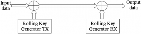
Because producing random numbers takes up a sizable portion of the processing time for applications requiring large volumes of random numbers, it is hoped that a hardware implementation of the random number generator will improve generation performance for simulation software. For the development of random number generators, FPGAs provide various advantages in speed, energy, power, and scalability [18]. See Figure 9:
Figure 9. Circular pseudo-random sequence generator usage
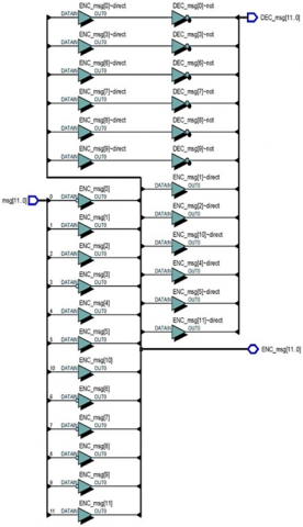
The FPGA netlist view implementation is shown in Figure 10. The work uses Altera Quartus Prime software. The application considers circular generation with a random sequence of length equal to 12 bits.
Reconfigurable hardware systems include FPGA chips. They enable rapid prototyping or quickly comparing many hardware options and choosing the best [19].
When using high-quality random numbers, they denote those bit sequences produced unpredictably. Higher quality (or security level) is associated with greater unpredictability [20].
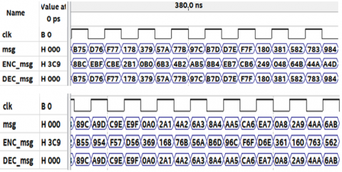
According to Shannon's postulate for theoretically unbreakable encryption, a pseudo-random bit sequence (PRBS) frequently serves as a "one-time padding" key sequence in reality and should have high statistical qualities, a complicated structure, and simplicity in execution [21]. The FPGA simulation waveform test is shown in Figure 11.
In Figure 11. Show the usage of a circular PN sequence generator as a scrambler. It is simple: generate the circular PN sequence and then XOR the input message with the circular PN sequence. To produce the scrambled data or coded data. At the receiver, side the reciprocal operation by re-XOR the coded data with the right circular PN sequence generator to restore and gain the original data, in Figure 10. The "msg" stands for input data message, "Enc-msg" stands for encoded data message, the output of XOR between the input data and circular PN sequence this in transmitter side. "Dec-msg" is the decoded message after XOR between the circular PN sequence and the received Encoded message. Sure, the Decode message will be the same as the input data message. The data representation in the waveform in Hexadecimal is more accessible to follow than binary mod.
Figure 10. Circular PN sequence generator FPGA implementation netlist view
Figure 11. Waveform/Timing diagram test showing encoded and decoded message
The current research paper presents a proposed pseudo-random sequence generator, introduces its mathematical model, and discusses its operation in illustrative examples. With its straightforward mathematical approach, this circular pseudo-random sequence generator may produce various lengths of random sequences, depending on the key. Additionally, it can offer adaptive operation when both sending and receiving agree. Furthermore, an FPGA implementation via Altera FPGA is discussed in this work. So, this random sequence generator is applicable. More importantly, the paper discusses two levels key in Example 3, but the structure may have several levels and a varied number of sectors, directions, and rotations. The construction decided by the designer and the validity of the application is considered. In addition, it takes the desired design's complexity into account. Finally, yet notably, this circular generator could be employed in security-related uses, particularly with systems that do not require sophisticated design and have the appropriate level of security.
[1] Alfke, P. (1996). Efficient shift registers, LFSR counters, and long pseudo-random sequence generators. Xilinx, XAPP 052: 1-6.
[2] Jun, B., Kocher, P. (1999). The Intel random number generator. Cryptography Research Inc. White Paper, 27: 1-8.
[3] Thomas, D.B., Luk, W., Leong, P.H., Villasenor, J.D. (2007). Gaussian random number generators. ACM Computing Surveys (CSUR), 39(4): 11-es. https://doi.org/10.1145/1287620.1287622
[4] Liu, Z., Huang, M., Zhu, S. (2009). The design and implementation of a pseudo random number generation algorithm. In 2009 International Conference on Computational Intelligence and Natural Computing, Wuhan, China, pp. 126-129. https://doi.org/10.1109/CINC.2009.242
[5] Gonzalez-Diaz, V.R., Pareschi, F., Setti, G., Maloberti, F. (2011). A pseudorandom number generator based on time-variant recursion of accumulators. IEEE Transactions on Circuits and Systems II: Express Briefs, 58(9): 580-584. https://doi.org/10.1109/TCSII.2011.2161165
[6] Chen, I.T., Tsai, J.M., Tzeng, J. (2011). Audio random number generator and its application. In 2011 International Conference on Machine Learning and Cybernetics, Guilin, China, pp. 1678-1683. https://doi.org/10.1109/ICMLC.2011.6017002
[7] Milinkovic, L., Malešević, B. (2012). Pseudo-random number generator analysis based on the set of quadratic irrationals. In 2012 20th Telecommunications Forum (TELFOR), pp. 536-539. https://doi.org/10.1109/TELFOR.2012.6419266
[8] Yadav, A. (2013). Design and analysis of digital true random number generator. MS.c. Thesis. Department of Electrical and Computer Engineering, Virginia Commonwealth University, Richmond, Virginia, USA.
[9] Kashmar, A., Ismail, E. (2015). Pseudorandom number generator using Rabbit cipher. Applied Mathematical Sciences, 9(88): 4399-4412. https://doi.org/10.12988/ams.2015.5143
[10] Luo, Y., Chang, K.T. (2016). Quantum random number generator vs. random number generator. 2016 International Conference on Communications, Bucharest, Romania, pp. 423-426. https://doi.org/10.1109/ICComm.2016.7528306
[11] Ergün, S. (2017). Algebraic break of a chaos-based random number generator. In 2017 11th International Conference on Signal Processing and Communication Systems (ICSPCS), Surfers Paradise, Australia, pp. 1-4. https://doi.org/10.1109/ICSPCS.2017.8270496
[12] Yu, F., Zhang, Z., Shen, H., Huang, Y., Cai, S., Jin, J., Du, S. (2021). Design and FPGA implementation of a pseudo-random number generator based on a hopfield neural network under electromagnetic radiation. Frontiers in Physics, 9: 690651. https://doi.org/10.3389/fphy.2021.690651
[13] Pallavi, Y., Leeladhar, K.K., Sainath, T.M. (2020). Implementation of chaos-based bitwise dynamical pseudo-random number generator based on FPGA technology. Journal of Interdisciplinary Cycle Research, XII(VI): 1059-1065.
[14] Garcia-Bosque, M., Pérez-Resa, A., Sánchez-Azqueta, C., Aldea, C., Celma, S. (2018). Chaos-based bitwise dynamical pseudorandom number generator on FPGA. IEEE Transactions on Instrumentation and Measurement, 68(1): 291-293. https://doi.org/10.1109/TIM.2018.2877859
[15] Tan, H., Chen, X., Chen, Y., He, B., Wong, W.F. (2021). ThundeRiNG: Generating multiple independent random number sequences on FPGAs. In Proceedings of the ACM International Conference on Supercomputing, Virtual Event, USA, pp. 115-126. https://doi.org/10.1145/3447818.3461664
[16] Yang, B. (2018). True random number generators for FPGAs. Ph.D. dissertation. Department of Electrical Engineering, Gent University, Belgium.
[17] Mahmood, B.S., Fakhrulddin Ismael, S. (2014). Architectural design of random number generators and their hardware implementations. Al-Rafidain Engineering Journal (AREJ), 22(2): 50-59. https://doi.org/10.33899/rengj.2014.87322
[18] Lee, J., Peterson, G.D., Harrison, R.J., Hinde, R.J. (2010). Implementation of hardware-accelerated scalable parallel random number generators. VLSI Design, 2010: 1-11. https://doi.org/10.1155/2010/930821
[19] Bakiri, M., Guyeux, C., Couchot, J.F., Oudjida, A.K. (2018). Survey on hardware implementation of random number generators on FPGA: Theory and experimental analyses. Computer Science Review, 27: 135-153. https://doi.org/10.1016/j.cosrev.2018.01.002
[20] Crocetti, L., Di Matteo, S., Nannipieri, P., Fanucci, L., Saponara, S. (2022). Design and test of an integrated random number generator with all-digital entropy source. Entropy, 24(2): 139. https://doi.org/10.3390/e24020139
[21] Mao, Y., Cao, L., Liu, W. (2006). Design and FPGA implementation of a pseudo-random bit sequence generator using spatiotemporal chaos. In 2006 International Conference on Communications, Circuits and Systems, Guilin, China, pp. 2114-2118. https://doi.org/10.1109/ICCCAS.2006.284916