Hari Maghfiroh*![]() | Alfian Ma’arif
| Alfian Ma’arif![]() | Feri Adriyanto
| Feri Adriyanto![]() | Iswanto Suwarno
| Iswanto Suwarno![]() | Wahyu Caesarendra
| Wahyu Caesarendra![]()
© 2023 IIETA. This article is published by IIETA and is licensed under the CC BY 4.0 license (http://creativecommons.org/licenses/by/4.0/).
OPEN ACCESS
An induction motor's speed can be managed in a variety of ways using a Variable Frequency Drive (VFD). In this study, the speed control of an induction motor will be controlled by applying Indirect Field Oriented Control (IFOC) combined with Linear Quadratic Gaussian (LQG). Conventional LQG control is a linear controller; therefore, if the system's dynamic is high and over the linear boundary, the LQG performance will not be optimal. Therefore, Adaptive LQG (ALQG) is proposed. Fuzzy logic is used as an adaptive algorithm with low complexity and ease of implementation. The significance of this study lies in its endeavor to tackle the challenges associated with nonlinearities and high dynamics in induction motor control. The average performance of speed variation and load variation tests proves that ALQG is superior in terms of settling time and undershooting than PID and LQG. PID has the highest overshoot with the smallest Integral Absolute Error (IAE). In comparison, ALQG is superior to conventional LQG in terms of IAE with 3.59% lower.
adaptive, fuzzy logic, induction motor, Linear Quadratic Gaussian (LQG), speed control
One technological development that can facilitate the production process is the electric motor. Two types of electric motors, AC and DC, depending on the supply current. The DC motor employs a mechanical commutator (brush), which increases maintenance costs even if it is easier to operate [1]. As a result, an AC motor is selected. The two types of AC motors are synchronous and asynchronous. The induction motor is one popular asynchronous motor type [2]. During installation and maintenance, the induction motor is economical, simple, and reliable [3, 4]. About 60% of the facility's energy is mainly used by induction motors [5]. There are wide applications for induction motors, such as compressors, elevators, centrifugal pumps [6, 7], and also as traction motors in electric vehicles [8, 9].
An induction motor's speed can be managed using a variable frequency drive (VFD) [3]. Figure 1 shows the classification of VFDs sensored (with a sensor) or unsensored (sensorless). The sensor-based control method will be employed in this study because the algorithm is simpler.
Scalar control and vector control are the two subtypes of sensor control. Scalar control is straightforward, easy, and parameter-independent [10, 11]. On the other hand, vector control has excellent controlling performance and is the most popular [12, 13]. Vector control is divided into Field Oriented Control (FOC) and Direct Torque Control (DTC). The FOC has a faster reaction and high efficiency. However, this method is sensitive to the parameter’s changes. On the other hand, DTC provides good performance and consideration for parameter variation [14]. The FOC approach is further broken down into Direct-FOC and Indirect-FOC (IFOC). According to the studies [15, 16], the IFOC approach has been widely applied. Therefore, the IFOC method is adopted in this study.
The scalar control and vector control are essentially torquing control; hence speed control requires a separate speed control mechanism. There are numerous speed control algorithms used in the speed control of induction motors, including PID [17], Linear Quadratic Regulator (LQR) [18, 19], Linear Quadratic Gaussian (LQG) [20-22], fuzzy logic controllers [23, 24], Sliding Mode Controllers (SMC) [25, 26], backstepping control [2], Artificial Neural Networks (ANNs) [27, 28] and some combination methods as in the studies [29, 30].
According to the study [31], LQG is one kind of optimal control that combines LQR and Kalman Filter. The use of the Kalman Filter to predict system states can reduce the number of sensors compared to the conventional LQR method. Conventional LQG control is a linear controller; therefore, if the system's dynamic is high and over the linear boundary, the LQG performance will not be optimal. Therefore, in this study, an Adaptive-LQG (ALQG) is proposed. With fuzzy logic as an adaptation algorithm, it can adapt to the plant condition allowing a wide operation range.
The previous study using adaptive LQG has been presented in the studies [32, 33]. Both previous studies used the Least Square Method (LSM) to update the LQG gain. However, the use of LSM is mathematically complicated. Therefore, the ALQG method using fuzzy logic as an adaptive algorithm with low complexity and ease of implementation is proposed. The objective is to get ALQG which is an LQG that can adapt to plant conditions and has a wide range of operations. Furthermore, the algorithm is simple and implementable. The simulation test is conducted under speed variation and load variation to prove the performance of the proposed method.
The rest of the paper is organized as follows. Section 2 briefly reviews induction motor control and the proposed control design. The simulation testing results are presented in Section 3. The last, Section 4 is the conclusions.
Figure 1. Induction motor control classification [5]
This study consists of several stages which are presented in Figure 2. The induction motor model was performed on the black box modelling method where the parameter value was based on a literature study. Then, the model is used in the ALQG design. The simulation is done in MATLAB Simulink. The last step is analyzing the result by comparing it with other control methods which are PID and conventional LQG.
Figure 2. Block diagram of the research step
2.1 Induction motor control
Figure 3 depicts the block diagram of VFD parts. Because the sensor base is the preferred control strategy, the speed sensor is used, in this study encoder. The controller in Figure 3 is a speed controller since the torque control is integrated into the inverter. Speed data must be collected and supplied to the inverter and controller for torque and speed control. The controller's output is a torque reference for the inverter's torque management.
Figure 3. General component of IM VFD
To validate the performance of the proposed control method, the simulation was built in the MATLAB Simulink software, as shown in Figure 4. There are two controllers in cascade form. The first one is the speed controller proposed in this study and the second one is vector control based on IFOC which employs hysteresis current control inside it. In the speed controller block, two options are using PID or LQG/ALQG since in this study we compare the performance of the proposed method with PID and conventional LQG. The induction motor parameters used in this study are listed in Table 1.
Table 1. Induction motor parameters
|
Parameters |
Value |
Unit |
|
Nominal power |
37.3 |
kVA |
|
Voltage (line-line) |
460 |
V-rms |
|
Frequency |
60 |
Hz |
|
Stator resistance |
0.087 |
Ohm |
|
Stator inductance |
0.0008 |
H |
|
Rotor resistance |
0.228 |
Ohm |
|
Rotor inductance |
0.0008 |
H |
|
Mutual inductance |
0.0347 |
H |
|
Pole pairs |
2 |
- |
The induction motor from the MATLAB model is extracted to obtain its state-space model using MATLAB System Identification Toolbox to simulate the actual situation. This strategy is considered to illustrate the step for actual implementation. This modelling method is also known as black-box modelling which only uses the input-output data of the system, as used in the study [34]. Instead of using the mathematical equation as in the studies [35, 36], this method is more suitable for hardware implementation where no system parameters are ready. In this study, the input-output data for modelling are torque and motor speed, respectively. The state-space model of the induction motor is presented in (1) consisting of two states which are speed and stator current. The speed is measured using the encoder, whereas the stator current is predicted using the Kalman Filter in the LQG control. This can reduce the number of sensors.
$\begin{gathered}\dot{x}=\left[\begin{array}{cc}1.378 & 0.285 \\ -1.25 & 0.06\end{array}\right] x+\left[\begin{array}{c}0.16 \\ -0.52\end{array}\right] u \\ y=\left[\begin{array}{ll}1 & 0\end{array}\right] x\end{gathered}$ (1)
Figure 4. Speed control of IM in MATLAB/Simulink software
2.2 ALQG design
The LQR is the state feedback control that minimizes a cost function, as presented in Eq. (2) [37, 38]. The matrices Q and R determine the relative importance of the error and energy expenditure [39]. LQG is the improvement of the LQR method which is a state-feedback control that requires all the state of the system. By adding the Kalman Filter (KF) [40, 41] as an observer, LQG can reduce the sensor used in the LQR method. Therefore, it can reduce equipment costs, especially the number of sensors. However, its robustness is not guaranteed [42]. Figure 5 shows the block diagram of LQG control which consists of LQR and Kalman Filter.
$J=\int\left(x^T(t) Q x(t)+u^T(t) R u(t)\right) d t$ (2)
$Q=\left[\begin{array}{cc}20 & 0 \\ 0 & 1\end{array}\right]; R=[1]$ (3)
Figure 5. LQG block diagram [36]
Conventional LQG control is a linear controller; therefore, if the system's dynamic is high and over the linear boundary, the LQG performance will not be optimal. Since LQG is the combination of LQR and Kalman Filter, this method has two gains: KLQR and Kf for LQR gain and Kalman Filter gain, respectively. In this study, matrix Q and R are chosen manually as shown in Eq. (3). In the matrix Q, the value of Q (1,1) which corresponds to the speed state is given the weight of 20. On the other hand, the value of Q (2,2) which is the weight of the stator’s current state is set to be 1. The R method is correlated with control effort, in this test it is set to be 1.
Figure 6. Proposed ALQG
Fuzzy logic is used as an adaptive algorithm whose output is a scaling value for LQR gain. The block diagram of the proposed ALQG is presented in Figure 6. The error signal between speed reference and speed output is sent to the integrator controller to eliminate steady-state error. The error and change are also sent to the fuzzy logic controller to generate a scaling factor for LQR gain. The adaptation mechanism is FLC determines the scaling factor based on the determined rules for KLQR. Therefore, the KLQR value can change based on the system condition in this case the error of speed tracking.
Table 2. LQG gains
|
Parameters |
X1 |
X2 |
|
KLQR |
4.64 |
1.02 |
|
Kf |
0.85 |
-0.88 |
Table 3. FLC rules
|
DE/E |
L |
M |
H |
|
L |
L |
L |
M |
|
M |
L |
M |
H |
|
H |
M |
H |
H |
Figure 7. FLC rules mesh diagram
Figure 8. ALQG control design process
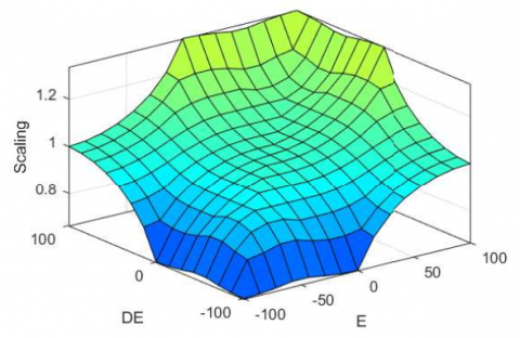
Table 2 shows the constant KLQR and Kf gain for the conventional LQG method. Table 3 is the fuzzy rule for KLQR adaptation with two inputs: speed error (E) and its change of error (DE). The output of the fuzzy system is a scaling factor that scales the KLQR gain, where L, M, and H present low, medium, and high, respectively. The rules are tuned manually with the principle that the higher the error, the higher the scaling factor. Both the input and output of a fuzzy system consist of three members of a triangular function. The mesh diagram, which shows the surface relation between the input and output of the fuzzy system is presented in Figure 7. It informs that the scaling factor used is 0.5 to 1.5, if the E and DE are negative, the scaling is below 1, whereas if it is positive, the value will be greater than 1. The scaling factor will be 1 if the E and DE are zero. Figure 8 shows the steps for designing the ALQG which uses black-box modelling based on input and output data of the motor namely torque and speed. Once the state-space model using MATLAB System Identification is obtained, the LQG control is designed before adding fuzzy logic to form ALQG.
The performance of the proposed method is tested in the simulation in the MATLAB software as shown in Figure 4. The performance is measured in terms of settling time, overshoot/undershoot, and Integral Absolute Error (IAE).
The model validation is conducted under conditions of speed and load fluctuation. The loaded test is done by giving torque to the motor shaft. The performance of the suggested control approach was demonstrated by comparison to the PID and LQG methods. The speed control in use has a tolerance of 2%.
3.1 Speed variation test
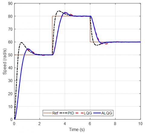
The objective of a speed variation is to evaluate how well the control method performs with the provided speed set points. In the simulation, the load was determined at 50Nm. The speed varied from the initial condition and increased gradually. Figure 9 displays the outcomes of the speed variation testing. A velocity graph, an Integral of Absolute Error (IAE), and a KLQR graph are all present.
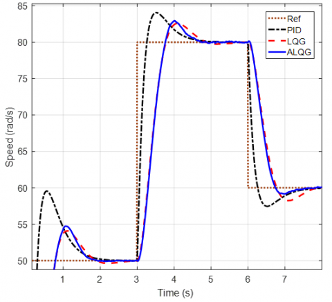
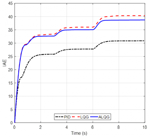
Figure 9(a) depicts the speed response of the control methods in the first test when tracking the speed references. All the control techniques are effective. Figure 9 (b) shows the zoomed-in version in more detail. Figure 9(b) shows that the PID has the highest overshoot and undershoot values. LQG and ALQG's quick replies differ slightly from one another. While Table 4 displays the quantitative outcomes. Figure 9(c) shows the IAE graph where PID has the lowest value, followed by ALQG and LQG. Figure 9(d) shows the KLQR value, which adapts to the system error and change of error based on fuzzy logic. The KX1 and KX2 oscillate between the value of 4.64 and 1.02, respectively, which is the constant gain value of LQR. Both KX1 and KX2 value increases when the error increases. Table 4 shows the results of speed tracking, including three set-point speeds, which are 50, 80, and 60 rad/s. Since there are three set-point values, the settling time and overshoot or undershot are measured in every value. In contrast, the IAE is derived as accumulation at the end of simulation time.
Figure 9. Speed variation test results: (a) speed responses; (b) zoom-in of speed responses; (c) IAE; (d) KLQR
According to the first set-point, PID has the lowest settling time, Figure 9(a). However, it also has the highest overshoot compared to others. LQG has the highest settling time with medium overshoot compared to PID and ALQG. Whereas the settling time of ALQG is higher compared to PID by 1.31% and lower compared to LQG by 6.63%. In terms of overshoot, the proposed method has lower and higher overshoot compared to PID and LQG by 50.42% and 15.89%. In the second set-point, is the same, ALQG settling time is in between PID and LQG. Whereas its overshoot is lower and upper by 27.27% and 14.29% compared to PID and LQR, respectively. In the last set-point, when speed reference decreases, ALQG dominates with the lowest settling time and no undershoot. While PID has a lower settling time with higher undershoot compared to LQG. The accumulative value of IAE shows that PID has the lowest value, LQG has the highest value, and ALQG is in the middle of them. The IAE of ALQG is higher than PID and lower than LQG by 84.08% and 3.15%, respectively.
Table 4. Speed variation test performances
|
Control Algorithm |
Settling Time (s) |
Undershoot (%) |
Overshoot (%) |
IAE |
|
Set-point 50 |
|
|
|
|
|
PID |
1.53 |
- |
19.12 |
|
|
LQG |
1.66 |
- |
8.18 |
- |
|
ALQG |
1.55 |
- |
9.48 |
- |
|
Set-point 80 |
|
|
|
|
|
PID |
1.03 |
|
5.09 |
|
|
LQG |
1.42 |
- |
3.24 |
- |
|
ALQG |
1.27 |
- |
3.70 |
- |
|
Set-point 60 |
|
|
|
|
|
PID |
0.96 |
4.23 |
|
23.37 |
|
LQG |
1.37 |
2.92 |
- |
44.42 |
|
ALQG |
0.66 |
- |
- |
43.02 |
3.2 Load variation test
The second test involves load variation. The objective of this test is to determine how well the motor speed control system performs under changing load conditions. This test can represent situations with ups and downs in the state of the roads for electric car applications.
Figure 10 shows the outcomes of the load variation test. The speed differences may be noted when the load is increased and decreased. The load starts at 50 Nm and keep constant for 3 seconds before being instantaneously increased to 100 Nm. The load is reduced to 20 Nm at the 6s and stays there until the simulation is finished.
In the load variation test, the speed graph in Figure 10(a), the settling time, overshoot, and undershoot of both ALQG and LQG look the same. For more detail, the zoomed-in version is presented in Figure 10(b). It is seen that in every speed change, each method has a different performance due to load variation. The quantitative result is resumed in Table 5. Regarding settling time, ALQG is superior, with 5.29% and 4.17% faster than PID and LQG, respectively. When the load increases, there is an undershot. In case of load decreases, all the control methods respond with overshoot. Since there are two overshoots, in the starting and when the load decreases, the maximum overshoot value is used. PID has the higher value of maximum overshoot; on the other side, LQG is the lowest one, whereas ALQG is in the middle of them. Although ALQG has a higher value of undershoot and overshoot than LQG, it can back to the references faster. Meanwhile, from the IAE perspective, Figure 10(c), the IAE of ALQG is higher than PID and smaller than LQG as in the speed variation test results. In this test, ALQG has higher and lower IAE by 25.46% and 4.06% compared to PID and LQG, respectively. Figure 10(d) shows the value changes of KLQR, where KX1 and KX2 correspond to the state gain of speed and stator current. Its value adaptively changes based on the value of error and change of error of the speed. Both have the same pattern where the higher error KLQR will have higher value.
Table 6 summarizes the average of all the test performed. The proposed ALQG is better than others in terms of settling time and undershoot. Although it has a higher overshoot than conventional LQG, it has a lower IAE. PID methods still have the lowest IAE value with the highest overshoot. Whereas the conventional LQG has the lowest overshoot with the highest settling time and undershoot.
Table 5. Load variation test performances
|
Control Algorithm |
Settling Time (s) |
Undershoot (%) |
Overshoot (%) |
IAE |
|
PID |
1.70 |
4.01 |
18.21 |
30.87 |
|
LQG |
1.68 |
5.79 |
9.31 |
40.37 |
|
ALQG |
1.61 |
6.40 |
9.75 |
38.73 |
Table 6. Average of all performances
|
Control Algorithm |
Settling Time (s) |
Undershoot (%) |
Overshoot (%) |
IAE |
|
PID |
1.31 |
2.06 |
10.61 |
13.56 |
|
LQG |
1.53 |
2.18 |
5.18 |
21.20 |
|
ALQG |
1.27 |
1.60 |
5.73 |
20.44 |
Table 7. Parametric sensitivity test results
|
Scaling Factor of FLC Output |
IAE |
|
0.5–1.5 |
43.12 |
|
0.7–1.3 |
44.17 |
|
0.2–1.8 |
48.93 |
Regarding the parametric sensitivities, the scaling factor affects the ALQG performance. As investigated on the speed tracking test, different scaling factors are tested. The results are resumed in Table 7. It informs that the scaling factor from fuzzy output needs to be carefully selected since the higher or lower range does not guarantee with best performance. Besides that, the fuzzy input and rules also affect the FLC performance as adaptive algorithms.
The ALQG method has been used to develop and simulate the speed control of the induction motor. Based on speed error and change of error, the LQG gain was scaled using fuzzy logic as an adaptive method. The objective to give the adaptable capability to the LQG method is achieved. The average results of the speed and load variations show that ALQG is superior in terms of settling time and undershoot. PID has the highest overshoot with the smallest IAE. Whereas ALQG is also superior to conventional LQG in terms of IAE. In terms of IAE, ALQG is in the middle of PID and LQG. The IAE of ALQG is higher than PID and lower than LQG by 50.72% and 3.59%, respectively. ALQG has the potential for better performance by proper tuning of fuzzy membership and or its rules. Fuzzy logic as adaptive algorithms are simple and easy to implement. Hence it can be combined with LQG for different motor loads and speed ranges. Future work to improve the performance of ALQG can be done by using artificial intelligence for fuzzy tuning to get the optimal results.
This work is supported by Universitas Sebelas Maret. The authors also gratefully acknowledge the helpful comments and suggestions of the reviewers, which have improved the presentation.
[1] Maghfiroh, H., Hermanu, C., Ibrahim, M.H., Anwar, M., Ramelan, A. (2020). Hybrid fuzzy-PID like optimal control to reduce energy consumption. Telecommunication Computing Electronics and Control, 18(4): 2053-2061. http://doi.org/10.12928/telkomnika.v18i4.14535
[2] Zahraoui, Y., Akherraz, M., Ma’arif, A. (2022). A comparative study of nonlinear control schemes for induction motor operation improvement. International Journal of Robotics and Control Systems, 2(1): 1-17. http://doi.org/10.31763/ijrcs.v2i1.521
[3] Maghfiroh, H., Titus, A.J., Sujono, A., Adriyanto, F., Saputro, J.S. (2022). Induction motor torque measurement using prony brake system and close-loop speed control. International Journal of Robotics & Control Systems, 2(3): 594-605. http://doi.org/10.31763/ijrcs.v2i3.782
[4] Swargiary, M., Dey, J., Saha, T.K. (2015). Optimal speed control of induction motor based on linear quadratic regulator theory. In 2015 annual IEEE India Conference (INDICON), New Delhi, India, pp. 1-6. http://doi.org/10.1109/INDICON.2015.7443806
[5] Alwadie, A. (2018). A concise review of control techniques for reliable and efficient control of induction motor. International Journal of Power Electronics and Drive Systems, 9(3): 1124. http://doi.org/10.11591/ijpeds.v9.i3.pp1124-1139
[6] Magzoub, M., Saad, N., Ibrahim, R., Irfan, M. (2019). An experimental demonstration of hybrid fuzzy-fuzzy space-vector control on AC variable speed drives. Neural Computing and Applications, 31: 777-792. http://doi.org/10.1007/s00521-017-3008-6
[7] Zahraoui, Y., Akherraz, M., Fahassa, C., Elbadaoui, S. (2022). Induction motor DTC performance improvement by reducing flux and torque ripples in low speed. Journal of Robotics and Control (JRC), 3(1): 93-100. http://doi.org/10.18196/jrc.v3i1.12550
[8] Maghfiroh, H., Wahyunggoro, O., Cahyadi, A.I., Lian, K.L., Ke, B.R. (2016). Speed control of a single Taipei mass rapid transit system train by using a single input fuzzy logic controller. International Journal of Electrical and Computer Engineering, 6(2): 621-629. http://doi.org/10.11591/ijece.v6i2.8123
[9] Islam, M.M., Siffat, S.A., Ahmad, I., Liaquat, M., Khan, S.A. (2021). Adaptive nonlinear control of unified model of fuel cell, battery, ultracapacitor and induction motor based hybrid electric vehicles. IEEE Access, 9: 57486-57509. http://doi.org/10.1109/ACCESS.2021.3072478
[10] Reza, C.M.F.S., Islam, M.D., Mekhilef, S. (2014). A review of reliable and energy efficient direct torque controlled induction motor drives. Renewable and Sustainable Energy Reviews, 37: 919-932. http://doi.org/10.1016/j.rser.2014.05.067
[11] dos Santos, T.H., Goedtel, A., da Silva, S.A.O., Suetake, M. (2014). Scalar control of an induction motor using a neural sensorless technique. Electric Power Systems Research, 108: 322-330. http://doi.org/10.1016/j.epsr.2013.11.020
[12] Hedjar, R., Boucher, P., Dumur, D. (2013). Robust nonlinear receding-horizon control of induction motors. International Journal of Electrical Power & Energy Systems, 46: 353-365. http://doi.org/10.1016/j.ijepes.2012.10.007
[13] Sutikno, T., Idris, N.R.N., Jidin, A. (2014). A review of direct torque control of induction motors for sustainable reliability and energy efficient drives. Renewable and Sustainable Energy Reviews, 32: 548-558. http://doi.org/10.1016/j.rser.2014.01.040
[14] Maghfiroh, H., Saputro, J.S., Fahmizal, F., Baballe, M.A. (2023). Adaptive fuzzy-PI for induction motor speed control. Journal of Fuzzy Systems and Control, 1(1): 1-5. http://doi.org/10.59247/jfsc.v1i1.24
[15] Bousserhane, I.K., Hazzab, A., Rahli, M., Kamli, M., Mazari, B. (2006). Adaptive PI controller using fuzzy system optimized by genetic algorithm for induction motor control. In 2006 IEEE International Power Electronics Congress, Puebla, Mexico, pp. 1-8. http://doi.org/10.1109/CIEP.2006.312162
[16] Hazzab, A., Bousserhane, I.K., Kamli, M. (2004). Design of a fuzzy sliding mode controller by genetic algorithms for induction machine speed control. International Journal of Emerging Electric Power Systems, 1(2). http://doi.org/10.2202/1553-779X.1016.
[17] Al-Manfi, A.A. (2018). Implementation of remote self-tuning fuzzy PID controller for induction motor through ethernet. In Proceedings of the International Conference on Recent Advances in Electrical Systems, Tunisia, pp. 12-17.
[18] Swargiary, M., Dey, J., Saha, T.K. (2017). Sensorless stator field-oriented digital control of induction motor based on LQR theory with augmented integral error. In 2017 IEEE International Conference on Power, Control, Signals and Instrumentation Engineering (ICPCSI), Chennai, India, pp. 1920-1925. http://doi.org/10.1109/ICPCSI.2017.8392050
[19] Janouš, Š., Talla, J., Šmídl, V., Peroutka, Z. (2020). Constrained LQR control of dual induction motor single inverter drive. IEEE Transactions on Industrial Electronics, 68(7): 5548-5558. http://doi.org/10.1109/TIE.2020.2994885
[20] Maghfiroh, H., Iftadi, I., Sujono, A. (2021). Speed control of induction motor using LQG. Journal of Robotics and Control (JRC), 2(6): 565-570. http://doi.org/10.18196/jrc.26138
[21] Sunori, S.K., Mittal, A., Bisht, V.S., Joshi, N., Garia, P., Juneja, P. (2022). LQG approach based speed control of induction motor. In 2022 3rd International Conference on Electronics and Sustainable Communication Systems (ICESC), Coimbatore, India, pp. 1-5. http://doi.org/10.1109/icesc54411.2022.9885696
[22] Sanz, J.C. (2004). LQG/LTR speed control of the field oriented induction motor with multirate Kalman filter. In 2004 IEEE International Conference on Industrial Technology, 2004. IEEE ICIT'04. pp. 1549-1554. http://doi.org/10.1109/icit.2004.1490797
[23] Fattah, A.J., Abdel-Qader, I. (2015). Performance and comparison analysis of speed control of induction motors using improved hybrid PID-fuzzy controller. In 2015 IEEE International Conference on Electro/Information Technology (EIT), Dekalb, IL, USA, pp. 575-580. http://doi.org/10.1109/EIT.2015.7293400
[24] Singh, A., Dipraj, Singh, D., Yadav, A. (2007). FLC based speed control of Induction Motor. Journal of Physics: Conference Series, 2007: 012020. http://doi.org/10.1088/1742-6596/2007/1/012020
[25] Nguyen, V.Q., Tran, Q.T., Duong, H.N. (2020). Stator-flux-oriented control for three-phase induction motors using sliding mode control. Journal of Electrical Systems, 16(2): 171-184.
[26] Hadda, B., Larbi, C.A., Abdessalam, M. (2018). A new technique of second order sliding mode control applied to induction motor. European Journal of Electrical Engineering, 20(4): 399-412. http://doi.org/10.3166/EJEE.20.399-412
[27] Kılıç, E., Özçalık, H.R., Şit, S. (2018). Adaptive controller with RBF neural network for induction motor drive. International Journal of Numerical Modelling: Electronic Networks, Devices and Fields, 31(3): e2280. http://doi.org/10.1002/jnm.2280
[28] Menghal, P.M., Laxmi, A.J. (2018). Real time control of induction motor using neural network. In 2018 International Conference on Communication information and Computing Technology (ICCICT), Mumbai, India, pp. 1-6. http://doi.org/10.1109/ICCICT.2018.8325873
[29] Ke, B.R., Maghfiroh, H., Lian, K.L., Chen, N., Teshome, D.F. (2016). Model of traction system and speed control for single train of Taipei mass rapid transit system. In 2016 IEEE International Conference on Advanced Intelligent Mechatronics (AIM), Banff, AB, Canada, pp. 781-787. http://doi.org/10.1109/AIM.2016.7576863
[30] Dhieb, Y., Yaich, M., Guermazi, A., Ghariani, M. (2019). PID controller tuning using ant colony optimization for induction motor. Journal of Electrical Systems, 15(1): 133-141.
[31] Syahidah, W.W., Rosli, O., Joraimee, M.A., Norhidayah, A. (2014). Linear quadratic gaussian (LQG) controller design for servo motor. Australian Journal of Basic and Applied Sciences, 8(4): 700-713.
[32] Ezzaraa, M., Ait Lafkih, M., Ramzi, M. (2013). Application of adaptive controllers to a DC-motor. International Journal of Systems, Control and Communications, 5(3-4): 179-188. http://doi.org/10.1504/IJSCC.2013.058174
[33] Sohn, H.C., Hong, K.T., Hong, K.S., Yoo, W.S. (2004). An adaptive LQG control for semi-active suspension systems. International Journal of Vehicle Design, 34(4): 309-326. http://doi.org/10.1504/IJVD.2004.004060
[34] Maghfiroh, H., Nizam, M., Anwar, M., Ma’Arif, A. (2022). Improved LQR control using PSO optimization and Kalman filter estimator. IEEE Access, 10: 18330-18337. http://doi.org/10.1109/ACCESS.2022.3149951
[35] Ebrahim, O.S., Salem, M.F., Jain, P.K., Badr, M.A. (2010). Application of linear quadratic regulator theory to the stator field-oriented control of induction motors. IET Electric Power Applications, 4(8): 637-646. http://doi.org/10.1049/iet-epa.2009.0164
[36] Abut, T. (2016). Modeling and optimal control of a DC motor. International Journal of Engineering Trends and Technology (IJETT), 32(3): 146-150. http://doi.org/10.14445/22315381/ijett-v32p227
[37] Dos Santos, G.P., Kossoski, A., Balthazar, J.M., Tusset, A.M. (2021). SDRE and LQR controls comparison applied in high-performance aircraft in a longitudinal flight. International Journal of Robotics and Control Systems, 1(2): 131-144. http://doi.org/10.31763/ijrcs.v1i2.329
[38] Önen, Ü., Çakan, A. (2021). Multibody modeling and balance control of a reaction wheel inverted pendulum using LQR controller. International Journal of Robotics and Control Systems, 1(1): 84-89. http://doi.org/10.31763/ijrcs.v1i1.296
[39] Ogata, K. (2010). Modern Control Engineering. Boston: Prentice Hall.
[40] Ma'arif, A., Iswanto, I., Nuryono, A.A., Alfian, R.I. (2019). Kalman filter for noise reducer on sensor readings. Signal and Image Processing Letters, 1(2): 50-61. http://doi.org/10.31763/SIMPLE.V1I2.2
[41] Alfian, R.I., Ma'arif, A., Sunardi, S. (2021). Noise reduction in the accelerometer and gyroscope sensor with the Kalman filter algorithm. Journal of Robotics and Control (JRC), 2(3): 180-189. http://doi.org/10.18196/jrc.2375
[42] Xie, S.Y., Wang, X.L., Qu, C., Wang, X.F., Guo, J.L. (2015). Impacts of different wind speed simulation methods on conditional reliability indices. International Transactions on Electrical Energy Systems, 25(2): 359-373. https://doi.org/10.1002/etep.1851