Mohammed Benslimane | Mokhtar Bendjebar*![]() | Debbagh Ammar Bouayed
| Debbagh Ammar Bouayed
© 2023 IIETA. This article is published by IIETA and is licensed under the CC BY 4.0 license (http://creativecommons.org/licenses/by/4.0/).
OPEN ACCESS
This paper presents a study focused on the operation of a twelve-sector direct torque control (DTC) structure under both healthy and faulty conditions for an induction motor (IM). The fault-tolerant control (FTC) discussed herein pertains to a three-phase two-level inverter based on an open-circuit fault of an insulated gate bipolar transistor (IGBT). In this scenario, the gate signal of the transistor is manually forced to zero. The proposed control mechanism is capable of maintaining stability at a certain minimum performance level. Experimental results, derived from testing the IM under both healthy and faulty modes using a Dspace 1104 board, display the commendable performance of the proposed control. This improved DTC strategy, bolstered by twelve sectors, has resulted in minimizing torque ripples, flux, and stator current oscillations, as compared to conventional DTC. The principle provides a robust solution that effectively reduces vibrations and audible noise.
induction motor, direct torque control, fault tolerant control, Ds1104
Nowadays, the availability and service continuity of electric drives requires an increase in performance and a reduction in downtime. Induction motors are widely used in many industrial processes because of their reliability low cost and control capabilities [1-3].
In recent years, FTC control systems have become a very motivating area of research for several research groups [4], as the reliability obtained by continuous operation brings advantages in terms of economy and safety [5]. In terms of safety, for example after an unexpected stop of an electric vehicle, the passengers will be in potential risk; such as military vehicles and ambulances [6].
According to the advancement in technology, FTC aims for assured operation even after a fault has occurred, leading to more sophisticated methods of fault detection (FD) and robust control in degraded mode [7-11]. There are two types of FTC: the so-called active and the other passive [3, 4, 9].
The active approach necessitates fault detection and isolation (FDI) block and a method of reconfiguring the control system according to the information generated by the FDI. The passive approach provides a robust control that can maintain the performance of an acceptable operation. The first fault tolerant control (FTC) is implemented in aircraft [9], it is later extended to several other domains, such as electric vehicles [12, 13], wind power conversion systems [14, 15] and in industry [16].
Moujahed et al. [17] describes an open circuit fault of a three-phase six-switch inverter feeding an induction motor. The authors propose a fault tolerant DTC that will allow maintaining the minimum performance level and a direct replacement of the faulty arm after its isolation by another redundant arm.
For the same fault in study [18], the authors have proposed a voltage reconfiguration fault tolerance for three-phase inverter.
In this sense, Maamouri et al. [19] proposes an experimental study of the robustness and availability of sensorless IM controls in the presence of single and multiple IGBT opening faults, using a sliding mode observer (SMO) based on the super twisting technique (STO), which maintains the good performance of estimating the machine state variables, even in faulty operating mode and during transient states, the fault compensation strategy is based on hardware redundancy.
Moujahed et al. [11] proposes a vision of a high performance sensorless control based on an extended Kalman filter (EKF) with estimation of the stator resistance applied to a drive composed of a three-phase PMSM and a three-phase inverter with four legs; the fourth one being the fault tolerant redundant leg; the authors proposed a method to detect the short circuit of the switch based on the analysis of the average stator current value.
In this context, a corrective strategy for a tolerant structure in degraded mode with direct torque control for an inverter under fault is presented by Restrepo et al. [20]. It proposes an alternative, reliable and prolonged operation by a double inverter.
Zhang et al. [6] present a topology of a fault tolerant inverter. The authors proposed the solutions which are always based on hardware redundancy in case a leg is lost Figure 1. The same paper appreciated that the parallel redundant converter approach is widely used due to its higher reliability.
The topology in Figure 1(a) and (b) is to connect the neutral point of the motor to the center point of a capacitor bank or to a fourth leg of the inverter. This approach to connecting the neutral and the triac has been used as a fault-tolerant solution pending final maintenance. If the neutral is not available [21] as shown in the topology in Figure 1(c), the faulty phase is forced to connect to the center point of the capacitors; one-way triacs are used to bypass the fault of the inverter.
Figure 1. Topology of a fault-tolerant inverter
In this regard, Meirinho et al. [22] discusses the use of direct torque control for phase-to-ground fault tolerance of a permanent magnet synchronous motor (PMSM) drive, which provides the necessary torque and current control. It can be used in electric vehicles and other industrial installations.
Similarly, a fault tolerant control scheme for a five-phase IM fed by a three-level inverter (NPC VSI), with a main concept of the DTC technique proved necessary for uninterrupted operation even after the occurrence of open phase fault [16]. A major advantage of the proposed study is that reconfiguration of the controller is not required when the fault occurs.
Similarly, in the same vein, our study is based on a fault-tolerant control law to ensure the maintenance of operation at a minimal acceptable level of performance in degraded mode. The solution can be a hardware redundancy as previously described in Figure 1, while awaiting the final resolution.
We continue our proposal with a simple contribution on fault-tolerant smooth control. Our study is different, as it is based on Direct Torque Control (DTC)in fault-tolerant mode at the level of the inverter supplying power to (IM).
In addition, Liu et al. [23] presents an FTC of IM drives with sensor failure. The published methods can be divided into two types: The first is a resilient method in which observers are used to provide the information initially provided by the faulty sensor. The second is a reconfigurable type, where one or more backup controllers not requiring the faulty sensor are applied to smoothly replace the original controller.
In this perspective, the studies [12, 24, 25] propose a reconfigurable type FTC method for driving electric motors, in case of mechanical sensor faults. The fault-tolerant controller allows the smooth transition from FOC to DTC control to ensure continuity of operation and without losing the motor performance.
Similarly, a non-smooth control approach applied to permanent magnet synchronous motor (PMSM) DTC is found in study [26], which includes a real-time disturbance observer to estimate the disturbed parameters (friction and load torque, etc.); an observed value is used as an estimate for compensation of localized system disturbances.
We conclude our suggestion with a simple survey or contribution by certain authors who have addressed fault tolerance in electrical machines.
They propose robust control laws, sometimes imposed by the specifications, in order to enable continuous operation while awaiting a maintenance operation. In comparison, our study proposes the same proposition and solution.
In this sense, Refaat et al. [27] proposes a possibility of a corrective operation with a remarkable and reliable indicator for the detection and diagnosis of winding faults using an artificial neural network that ensures a fault tolerance between turns with a DTC while adjusting the stator resistance of the IM. This allows a continuous operation without disturbance, even in the presence of winding faults.
In the study [3], a sensorless robust fault tolerant controller implementation for IM based on a backstepping strategy is presented, which is designed to compensate for load torque disturbances and rotor resistance variations caused by broken motor rotor bars. The authors have shown the performance of the machine even after the fault. The proposed approach does not require a diagnostic block or controller reconfiguration.
Guezmil et al. [28] propose in the same context, an unknown input observer system that can solve the problem of inter-winding short circuit fault recognition because it can separate the input disturbances and model errors for an induction machine. This method is developed using a backstepping controller in order to compensate for the impact of partial short circuit fault of the stator winding or load torque disturbances.
Saad et al. [29] uses a new type-2 fuzzy logic controller to improve the performance of the conventional PI controller of the indirect field orientation control (IFOC) strategy with broken bars. They also showed improved robustness against parametric motor disturbances.
Similarly, the test results confirm that the hybrid approach is robust to changes in IM parameters [30].
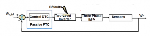
The present paper examines an experimental study similar to a passive fault tolerant control that does not necessitate fault identification (Figure 2).
Figure 2. Passive fault tolerant control (PFTC)
The proposed approach consists in designing a robust control based on the direct torque control of an IM fed by an inverter under fault. This control is now considered as a high-performance control strategy because of its fast torque and its robustness to variations and disturbances of the machine parameters [13].
The studies [3-5, 16-31] have dealt with passive type fault tolerant controls that can be applied in critical systems, waiting for the final restoration. In this paper study, the case of both a healthy operation as well as the case of open circuit fault of the inverter switches are considered.
The experimental implementation of the DTC algorithm is developed using an interface linked to a Dspace1104 board, a digital signal processor based on Matlab/Simulink graphical programming approach. The sampling time can reach up to (5.10-5s) [32], the choice is set to an appropriate sampling time (10-4s) to minimize the different output harmonics.
The dynamic equation’s model of the induction motor which is dedicated for direct torque control is expressed below in Eq. (1) and Eq. (2). It can be written in the stator fixed reference frame (α, β) (stationary frame) by assuming the stator current and the stator flux as state variables.
$\left\{\begin{array}{l}\frac{d i_{s \alpha}}{d t}=-\left(\frac{R_s}{\sigma L_s}+\frac{R_R}{\sigma L_r}\right) i_{s \alpha}-\omega_r i_{s \beta}+\frac{R_s}{\sigma L_s L_r} \psi_{s \alpha}+\frac{\omega_r}{\sigma L_r} \psi_{s \beta}+\frac{1}{\sigma L_s} u_{s \alpha} \\ \frac{d i_{s \beta}}{d t}=-\left(\frac{R_s}{\sigma L_s}+\frac{R_R}{\sigma L_r}\right) i_{s \beta}+\omega_r i_{s \alpha}+\frac{R_s}{\sigma L_s L_r} \psi_{s \beta}-\frac{\omega_r}{\sigma L_r} \psi_{s \alpha}+\frac{1}{\sigma L_s} u_{s \beta}\end{array}\right.$ (1)
$\left\{\begin{array}{l}\frac{d \psi_{s \alpha}}{d t}=u_{s \alpha}-R_s i_{s \alpha} \\ \frac{D \psi_{s \beta}}{d t}=u_{s \beta}-R_s i_{s \beta}\end{array}\right.$ (2)
where,
$i_{s \alpha}$ and $i_{s \beta}$ : Stator current components.
$\psi_{s \alpha}$ and $\psi_{s \beta}$ : Stator flux components.
$R_s$ and $R_r$ : Stator and rotor resistance respectively.
$L_s$ and $L_r$ : Stator and rotor inductance respectively.
$\sigma=1-\frac{M_{S r}^2}{L_S L_r}$ : Blondel coefficient.
$M_{s r}$ : Mutual stator-rotor inductance.
The DTC control strategy is based on the direct determination of pulses applied to the voltage inverter switches, in order to maintain the electromagnetic torque Te and the stator flux Ψs within two predefined hysteresis bands and without measuring them. These two quantities Te and Ψs are estimated from the measurements of the supply voltages and the stator currents of the IM.
The estimation of the stator flux is usually done by the integration of the back-emf (Electromotive force). The stator flux components can be expressed using stator voltages and currents in the stationary reference frame (α, β) by:
$\Psi_{S \alpha}=\int_0^t\left(V_{S \alpha}-R_s i_{S \alpha}\right) d t$ (3)
$\Psi_{S \beta}=\int_0^t\left(V_{S \beta}-R_s i_{S \beta}\right) d t$ (4)
The stator voltage components (Vα, Vβ) are obtained by applying Concordia transformation on the output voltage of the three-phase VSI.
The stator currents components (iα, iβ) can be obtained also by applying Concordia transformation on the measured currents. The stator flux magnitude and flux angle can be computed as:
$|\Psi|_s=\sqrt{\Psi_{\alpha s}{ }^2+\Psi_{\beta s}{ }^2}$ (5)
$\theta_s=\operatorname{arctg}\left(\frac{\Psi_{s \beta}}{\psi_{s \alpha}}\right)$ (6)
The produced electromagnetic torque of the induction motor can be determined using the cross product of the stator quantities (i.e., stator flux and stator currents). The torque formula is expressed as following:
$T_e=p\left(\psi_{s \alpha} i_{s \beta}-\psi_{s \beta} i_{s \alpha}\right)$ (7)
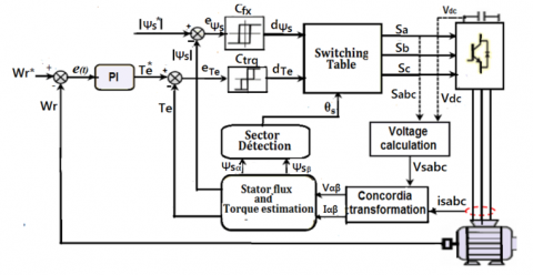
The errors in the stator flux eΨs and the electromagnetic torque Te signals are fed to two hysteresis controllers as shown in Figure 3.
Figure 3. Basic configuration of classical DTC scheme
The stator flux controller (Cfx) imposes the duration of the active voltage vectors which move the stator flux along the reference path and the torque controller (Ctrq) determines the duration of the zero voltage vectors that keep the motor torque within the tolerance band defined by the hysteresis [33].
The corresponding output variables dΨs, dTe and the stator flux position sector θs used to select the appropriate voltage vector from the resulting look-up table for DTC which was proposed by Takahashi is presented in Table 1.
The complete structure of the twelve-sector DTC for IM is shown in Figure 3.
Table 1. Look-up table for basic direct torque control [34]
|
Sectors Cflx Ctrq |
S1 |
S2 |
S3 |
S4 |
S5 |
S6 |
|
|
0 |
1 |
V2 |
V3 |
V4 |
V5 |
V6 |
V1 |
|
0 |
V7 |
V0 |
V7 |
V0 |
V7 |
V0 |
|
|
-1 |
V6 |
V1 |
V2 |
V3 |
V4 |
V5 |
|
|
1 |
1 |
V3 |
V4 |
V5 |
V6 |
V1 |
V2 |
|
0 |
V0 |
V7 |
V0 |
V7 |
V0 |
V7 |
|
|
-1 |
V5 |
V6 |
V1 |
V2 |
V3 |
V4 |
|
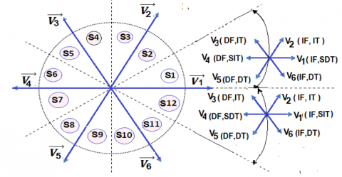
According to the research table (Table 1), there are two states per sector that are not utilized (such as V1 and V4 in the first sector) because they can simultaneously increase or decrease the torque depending on the position of the flux vector in the first or second sector. The solution is an improvement through twelve sectors. The location of the circular flux is divided into 12 sectors instead of 6, as shown in Figure 4, and the six voltage vectors will be used for the same sector. V0 and V7 are zero voltage vectors [32, 34, 35].
Table 2 shows the cases where the 6 voltage vectors can be used in the S1and S12 sectors.
Figure 4. Voltage space vector in 12 sectors case
Note: IT: Increase torque, DT: Decrease torque, IF: Increase flux, DF: decrease flux, SIT Small increase torque, SDT: Small decrease torque
Table 2. Effect of the six voltage vectors used in sectors S1 and S12
|
Sector: S1 |
Increase |
Decrease |
|
Ψs |
V1, V2, V6 |
V3, V4, V5 |
|
Te |
V2, V3, V4 |
V5, V6, V1 |
|
Sector: S12 |
Increase |
Decrease |
|
Ψs |
V1, V2, V6 |
V3, V4, V5 |
|
Te |
V1, V 2, V3 |
V4, V5, V6 |
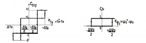
(a) Torque (b) Flux
Figure 5. Hysteresis comparator
Table 3. Switching table for DTC 12 sectors
|
Sectors |
S1 |
S2 |
S3 |
S4 |
S5 |
S6 |
|
|
Cflx |
Ctrq |
||||||
|
0 |
2 1 |
V2 *V2 |
V3 V2 |
V3 *V3 |
V4 V3 |
V4 *V4 |
V5 V4 |
|
-1 -2 |
V1 V6 |
*V1 V1 |
V2 V1 |
*V2 V2 |
V3 V2 |
*V3 V3 |
|
|
1 |
2 1 |
V3 V4 |
V4 *V4 |
V4 V5 |
V5 *V5 |
V5 V6 |
V6 *V6 |
|
-1 -2 |
V7 V5 |
V5 V6 |
V0 V6 |
V6 V1 |
V7 V1 |
V1 V2 |
|
|
Sectors |
S7 |
S8 |
S9 |
S10 |
S11 |
S12 |
|
|
Cflx |
Ctrq |
||||||
|
0 |
2 1 |
V5 *V5 |
V6 V5 |
V6 *V6 |
V1 V6 |
V1 *V1 |
V2 V1 |
|
-1 -2 |
V4 V3 |
*V4 V4 |
V5 V4 |
*V5 V5 |
V6 V5 |
*V6 V6 |
|
|
1 |
2 1 |
V6 V1 |
V1 *V1 |
V1 V2 |
V2 *V2 |
V2 V3 |
V3 *V3 |
|
-1 -2 |
V0 V2 |
V2 V3 |
V7 V3 |
V3 V4 |
V0 V4 |
V4 V5 |
|
In order to make better use of these voltages, it is necessary to define the small and large variations in torque and flux generated by these same voltages as a function of their phase shift with respect to the limits of the sectors. For example, it is obvious that V1 can produce a large increase in flux and a small increase in torque for sector 12.
On the other hand, in the same sector, V2 greatly increases the torque and slightly the flux.
In our case, the torque is more interesting, so to take into account for low and high variations of the torque, a four level hysteresis comparator for torque and a two level hysteresis for flux are used, see Figure 5 [35].
Finally, the selection table for this technique is given in Table 3 [35]. Noting that: (2, -2) large torque variation; (1, -1) small torque variation; *Vi represents an undesired sequence, because it does not generate the desired small torque variations.
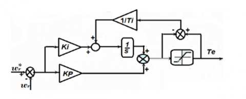
The speed controller used is an anti-windup PI controller (Figure 6) is used to obtain a high-performance speed control and to generate a torque reference by cancelling the runaway phenomenon which is caused by the saturation of the pure integrator [32].
Figure 6. Speed anti-windup PI controller
To overcome this phenomenon, the strategy is to correct the integral action based on the difference between the control signal and the saturation limit crosses through a gain block (tracking time constant Ti) before arriving as feedback to the integrator.
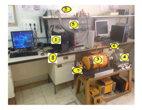
In this section, the DTC command in the healthy and faulty cases is validated as shown in Figure 7. The test bench is composed of the following elements (Figure 8).
1: A PC is used for software development and visualization of results.
2: A dSpace1104 board connected to the PC and controlled by the control software.
3: A separately excited generator supplying resistive loads.
4: A 3Kw three-phase induction motor whose stator windings are connected in delta under a 380v power supply. The parameters of the IM are given in Table 4.
5: A SEMIKRON power converter composed of a rectifier and a three-phase inverter.
6: Two current sensors.
7: A Speed sensor to check its measurement with the speed reference.
8: A DC bus voltage sensor.
Figure 7. Overview of experimental electrical drive system
Figure 8. Photo of the measuring bench
An open-circuit fault in the gate drive can occur due to the lifting of bonding wires caused by thermal cycling. It can be triggered by a driver fault or by the rupture of an IGBT induced by a short circuit. Open circuit faults typically do not cause the system to shut down, but they do degrade its performance. Consequently, these diagnostic methods can be used in fault-tolerant component systems [36].
We affirm that our study is based on a direct fault-tolerant torque control which can maintain minimal performance without diagnostic blocking, with the same fault (open circuit), pending final maintenance.
The acquisition of state variables is done in both normal and fault modes using the control desk.
Table 4. Parameters induction motor
|
Induction Motor Parameters |
|
|
U |
380V |
|
PN |
3kw |
|
CN |
20Nm |
|
Is |
7A |
|
Rs |
6Ω |
|
Rr |
2.8Ω |
|
Ls |
0.5668H |
|
Lr |
0.5142H |
|
Msr |
0.5142H |
|
p |
2 |
|
J |
0.058kgm |
|
f |
0.005Nm/rad/s |
The components Vsα and Vsβ can be obtained from measuring the three voltages van, vbn, and vcn. This requires the installation of additional sensors and increase the cost of the implementation. In our steady. VSα and VSβ are obtained from the commands (Sa, Sb, Sc) and the measurement of the DC voltage E. By applying the Park transformation [33], we have:
$V_{S \alpha}=\sqrt{\frac{2}{3}} E\left(S_a-\frac{1}{2}\left(S_b-S_c\right)\right)$ (8)
$V_{\mathrm{S} \beta}=\frac{1}{\sqrt{2}} E\left(\mathrm{~S}_{\mathrm{a}}-\mathrm{S}_{\mathrm{c}}\right)$ (9)
5.1 Healthy operation
Figures 9(a)-(h) depict successively the waveforms for healthy operation of the electromagnetic torque, the stator currents, the rotational speed, the flux magnitude and its position, their trajectory in the α-β plane, the 12 sectors circular flux and the stator voltages Vα, Vβ with load introduction at 5.5s. The results of the experimental tests are presented on the software interface of the control desk in Figure 10.
(a) Electromagnetique torque (N)
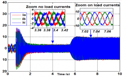
(b) Stator line currents (A)
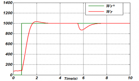
(c) Rotor speed (Rpm)
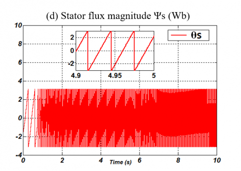
(d) Stator flux magnitude Ψs (Wb)
(e) Stator flux angle θs (Rad)
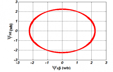
(f) Stator flux circular trajectory
(g) Twelve sectors stator flux trajectory
(h) α-β stationary line voltages (V)
Figure 9. Experimental results DTC for healthy operation (at 5.5s and Cn=20mN)
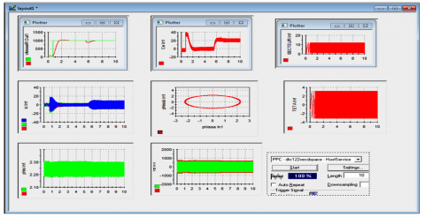
Figure 10. Software interface control desk (healthy operation)
5.2 Faulty operation
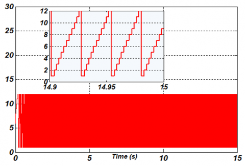
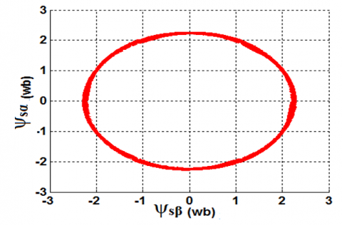
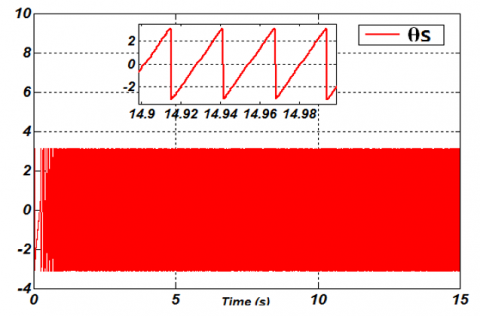
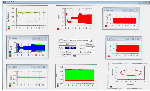
Figures 11(a)-(h) successively show the waveforms for a faulty operation state such: the electromagnetic torque, the stator currents, the rotational speed, the flux magnitude and its position, their trajectory in the α-β plane, the 12 sectors circular flux and the stator voltages Vα, Vβ. The results obtained from the DTC with a fault and in tolerated mode are presented on the software control panel interface in Figure 12, the fault is introduced at time t=7s and the load is introduced at 2.5s.
(a) Electromagnetic torque (N)
(b) Stator line currents (A)
(c) Rotor speed (Rpm)
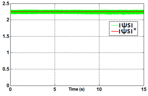
(d) Stator flux magnitude Ψs (Wb)
(e) Stator flux angle θs (Rad)
(f) Stator flux circular trajectory
(g) Twelve sectors stator flux trajector
(h) α-β Stationary line voltages (V)
Figure 11. Experimental results DTC with fault tolerated at 7s
Figure 12. Software interface control panel (faulty operation state)
6.1 Healthy state
The static and dynamic performances of the DTC driving the IM in real time are illustrated in Figure 9 by applying a nominal load torque of 20mN after a no-load start, the stator flux reference is maintained at 2.25 Wb.
As can be seen in Figure 9(a), the torque shows a good response with some ripple due to the hysteresis controller used.
The currents in Figure 9(b) maintain an almost sinusoidal waveform. Figure 9(c) shows that the speed is obtained with a slight overshoot during start-up and a rapid disturbance when applying the load.
Figure 9(d) indicates that the magnitude of the stator flux vector follows perfectly the reference flux. Figures 9(e)-(f) depict respectively the position of the angle θs between π and -π radian and the stator flux evolution which is perfectly circular in the (α-β) plane.
Figure 9(g) illustrates the twelve sectors for operating 6 active voltage vectors by sectors. As for the voltage components (Vα, Vβ) of Figure 9(h), they have rectangular waveforms corresponding to the decoupling of the inverter supply voltage.
As can be seen in all the figures without faults, the developed DTC achieves a no-load and load operating performance that has allowed a good torque response and these quantities have rectangular shapes with a slight deformation. It can be concluded that the proposed control is robust with fault tolerant capability.
6.2 Faulty state
It is noticed that the effect of a single fault at the inverter level causes an increase in the electromagnetic torque of the IM to 30mN with a noisy signal as seen in Figure 11(a).
When the fault appears, it can be seen that the stator current of one phase is cancelled in the positive alternation as seen in Figure 11(b)due to the faulty transistor at the top of the first leg. Generally, the IGBT open-circuit fault is indicated by the loss of a positive or negative half-cycle of the inverter's output current, depending on the location of the damaged component within the faulty leg.
Figure 11(c) shows that the speed continues to rotate in real time in a stable manner for a tolerated fault at t = 7s after a slight disturbance.
In Figure 11(d), the stator flux vector modulus follows the reference without deterioration. Figure 11(e) shows the position angle θ between π and -π radian of stator flux and describes a circular path as illustrated in Figure 11(f) by comparison as in the healthy state.
Figure 11(g) shows the twelve sectors and the voltages (Vα, Vβ) are indicated in Figure 11(h).
The state variables obtained under normal and faulty conditions for Figures 9 and 11 are closely aligned, nevertheless. Upon the occurrence of a fault, disturbances prevail at the level of torque and currents. However, the operating tolerance presents an image of system robustness.
This paper deals with the experimental use of DTC of an induction motor fed by an inverter under healthy and faulty states. The experimental results allowed to find the classical waveforms of the machine in healthy and faulty state and to design the fault tolerant strategy. This strategy has the advantage of controlling the stator flux and the electromagnetic torque in a satisfactory way and ensures a powerful stability at a minimal level in case of fault occurrence. This situation enables the industrialists to maximize their productivity by minimizing the production stops and improving the availability of their equipment.
For future work, the current fault-tolerant control method can be enhanced through an advanced technique that requires fault detection and isolation (FDI), as well as a method for reconfiguring the control law in order to maintain system stability and performance.
|
DTC |
direct torque control |
|
IGBT |
insolated gate bipolar transistor |
|
IM |
induction motor |
|
FTC |
fault tolerant control |
|
isα |
α-Stator current component, A |
|
isβ |
β- stator current component, A |
|
Ψsα |
α- component stator flux, Wb |
|
Ψsβ |
β- component stator flux. Wb |
|
׀ψs׀ |
magnitude stator flux, Wb |
|
׀ψs׀* |
stator flux reference, Wb |
|
RS |
stator resistance, Ω |
|
Rr |
rotor resistance, Ω |
|
Ls |
stator inductance, H |
|
Lr |
rotor inductance, H |
|
Msr |
mutual stator-rotor inductance, H |
|
p |
number of pair poles |
|
J |
moment of inertia, Kg.m2 |
|
f |
coefficient of viscous friction, N/rad/s |
|
U |
nominal compound voltage, V |
|
PN |
nominal power, W |
|
CN |
nominal torque, Nm |
|
Is |
nominal line current, A |
|
ia |
stator line current phase a, A |
|
ib |
stator line current phase b, A |
|
ic |
Stator line current phase c, A |
|
Te |
mesured electromagnetique torque, N |
|
Te* |
torque reference, N |
|
wr |
rotor speed, Rpm |
|
wr* |
reference speed, Rpm |
|
e(t) |
speed error |
|
eψs |
flux error |
|
eTe |
torque error |
|
Ctrq |
the torque controller |
|
Cflx |
the stator flux controller |
|
dψs |
output variable stator flux controller |
|
dTe |
output variable torque controller |
|
Ki |
integral gain |
|
Kp |
proportional gain |
|
θs |
flux angle stator, Rad |
|
Vdc |
DC bus-voltage, V |
|
Vα |
α-stationary line voltage, V |
|
Vβ |
β-stationary line voltage, V |
|
VSI |
voltage source inverter |
|
FDI |
fault detection and isolation |
[1] Jlassi, I., El Khil, S.K. (2014). A MRAS-Luenberger observer based fault tolerant control of PMSM drive. Journal of Electrical Systems, 10(1): 48-62.
[2] Kumar, M.D., Kodad, S.F., Sarvesh, B. (2017). Fault analysis for voltage source inverter driven induction motor drive. International Journal of Electrical Engineering & Technology, 8(1): 1-8.
[3] Djeghali, N., Ghanes, M., Djennoune, S., Barbot, J.P. (2013). Sensorless fault tolerant control for induction motors. International Journal of Control, Automation and Systems, 11: 563-576. https://doi.org/10.1007/s12555-012-9224-z
[4] Klimkowski, K., Dybkowski, M. (2015). Adaptive fault tolerant direct torque control structure of the induction motor drive. In 2015 International Conference on Electrical Drives and Power Electronics (EDPE), Tatranska Lomnica, Slovakia, pp. 7-12. https://doi.org/10.1109/EDPE.2015.7325261
[5] Prieto, I.G., Duran, M.J., Garcia-Entrambasaguas, P., Bermudez, M. (2019). Field-oriented control of multiphase drives with passive fault tolerance. IEEE Transactions on Industrial Electronics, 67(9): 7228-7238. https://doi.org/10.1109/TIE.2019.2944056
[6] Zhang, W., Xu, D., Enjeti, P.N., Li, H., Hawke, J.T., Krishnamoorthy, H.S. (2014). Survey on fault-tolerant techniques for power electronic converters. IEEE Transactions on Power Electronics, 29(12): 6319-6331. https://doi.org/10.1109/TPEL.2014.2304561
[7] Klimkowski, K., Dybkowski, M. (2016). A fault tolerant control structure for an induction motor drive system. Automatika, 57(3): 638-647.https://doi.org/10.7305/automatika.2017.02.1642
[8] Berriri, H., Naouar, M.W., Slama-Belkhodja, I. (2011). Easy and fast sensor fault detection and isolation algorithm for electrical drives. IEEE Transactions on Power Electronics, 27(2): 490-499. https://doi.org/10.1109/TPEL.2011.2140333
[9] Bouakoura, M., Nait-Said, N., Nait-Said, M.S., Belbach, A. (2018). Novel speed and current sensor FDI schemes with an improved AFTC for induction motor drives. Advances in Electrical and Electronic Engineering, 16(1):2573. https://doi.org/10.15598/aeee.v16i1.2573
[10] Sobanski, P., Orlowska-Kowalska, T. (2015). Experimental validation of the simple voltage-vector-location-based method of open-circuit IGBTs faults in DTC-SVM induction motor drive. In 2015 International Conference on Electrical Drives and Power Electronics (EDPE), Tatranska Lomnica, Slovakia, pp. 19-24. https://doi.org/10.1109/EDPE.2015.7325263
[11] Moujahed, M., Touaiti, B., Benazza, H., Jemli, M., Boussak, M. (2018). Extended Kalman filter for sensorless fault tolerant control of PMSM with stator resistance estimation. International Journal of Power Electronics and Drive Systems, 9(2): 579-590. https://doi.org/10.11591/ijpeds.v9.i2.pp579-590
[12] Sajitha, G., Mayadevi, N., Mini, V.P., Harikumar, R. (2019). Fault-tolerant control of BLDC motor drive for electric vehicle applications. In 2019 International Conference on Power Electronics Applications and Technology in Present Energy Scenario (PETPES), Mangalore, India, pp. 1-6. https://doi.org/10.1109/PETPES47060.2019.9003925
[13] Tabbache, B., Benbouzid, M., Kheloui, A., Bourgeot, J.M. (2012). DSP-based sensor fault detection and post fault-tolerant control of an induction motor-based electric vehicle. International Journal of Vehicular Technology, 2012: 608381. https://doi.org/10.1155/2012/608381
[14] Attoui, I., Omeiri, A. (2014). Modeling, control and fault diagnosis of an isolated wind energy conversion system with a self-excited induction generator subject to electrical faults. Energy Conversion and Management, 82: 11-26. https://doi.org/10.1016/j.enconman.2014.02.068
[15] Freire, N.M., Cardoso, A.J.M. (2013). A fault-tolerant direct controlled PMSG drive for wind energy conversion systems. IEEE Transactions on Industrial Electronics, 61(2): 821-834. https://doi.org/10.1109/TIE.2013.2251734
[16] Chikondra, B., Muduli, U.R., Behera, R.K. (2020). Open-phase fault-tolerant direct torque control for five-phase three-level NPC VSI fed induction motor drive. In 2020 IEEE International Conference on Power Electronics, Drives and Energy Systems (PEDES), Jaipur, India, pp. 1-6. https://doi.org/10.1109/PEDES49360.2020.9379786
[17] Moujahed, M., Jemli, M., Boussak, M. (2014). Direct torque control of three-phase PMSM with one switch of inverter open fault. In 2014 15th International Conference on Sciences and Techniques of Automatic Control and Computer Engineering (STA), Hammamet, Tunisia, pp. 400-404. https://doi.org/10.1109/STA.2014.7086736
[18] Mohammedi, M.M., Bendiabdellah, A., Allaoui, T. (2022). Voltage reconfiguration fault-tolerant technique for two-level three-phase inverter integrated in a wind energy system. International Journal of Modelling, Identification and Control, 40(4): 315-326. https://doi.org/10.1504/IJMIC.2022.125550
[19] Maamouri, R., Trabelsi, M., Boussak, M., M'Sahli, F. (2021). Second-order SMO-based sensorless control of IM drive: Experimental investigations of observer sensitivity and system reconfiguration in postfault operation mode. IET Electric Power Applications, 15(7): 811-823. https://doi.org/10.1049/elp2.12057
[20] Restrepo, J.A., Berzoy, A., Ginart, A.E., Aller, J.M., Harley, R.G., Habetler, T.G. (2011). Switching strategies for fault tolerant operation of single DC-link dual converters. IEEE Transactions on Power Electronics, 27(2): 509-518. https://doi.org/10.1109/TPEL.2011.2161639
[21] Trabelsi, M., Boussak, M. (2014). Sensorless speed control of VSI-fed induction motor drive under IGBT open-switch damage: Performances and fault tolerant analysis. In 2014 International Conference on Electrical Sciences and Technologies in Maghreb (CISTEM), Tunis, Tunisia, pp. 1-8. https://doi.org/10.1109/CISTEM.2014.7368727
[22] Meirinho, C.J., de Oliveira, J., Cavalca, M.S.M., Nied, A. (2017). Fault tolerant control for permanent magnet synchronous motor. In 2017 IEEE International Electric Machines and Drives Conference (IEMDC), Miami, FL, USA, pp. 1-8. https://doi.org/10.1109/IEMDC.2017.8002217
[23] Liu, Y., Stettenbenz, M., Bazzi, A.M. (2018). Smooth fault-tolerant control of induction motor drives with sensor failures. IEEE Transactions on Power Electronics, 34(4): 3544-3552. https://doi.org/10.1109/TPEL.2018.2848964
[24] Abassi, M., Khlaief, A., Saadaoui, O., Chaari, A., Boussak, M. (2016). Fault tolerant control and reconfiguration for three-phase permanent magnet synchronous motors drive. In 2016 4th International Conference on Control Engineering & Information Technology (CEIT), Hammamet, Tunisia, pp. 1-6. https://doi.org/10.1109/CEIT.2016.7929053
[25] Gaeid, K.S., Ping, H.W., Khalid, M., Masaoud, A. (2012). Sensor and sensorless fault tolerant control for induction motors using a wavelet index. Sensors, 12(4): 4031-4050. https://doi.org/10.3390/s120404031
[26] Xia, C., Li, S., Shi, Y., Zhang, X., Sun, Z., Yin, W. (2019). A non-smooth composite control approach for direct torque control of permanent magnet synchronous machines. IEEE Access, 7: 45313-45321. https://doi.org/10.1109/ACCESS.2019.2905103
[27] Refaat, S.S., Abu-Rub, H., Iqbal, A. (2015). ANN-based system for inter-turn stator winding fault tolerant DTC for induction motor drives. In 2015 17th European Conference on Power Electronics and Applications (EPE'15 ECCE-Europe), Geneva, Switzerland, pp. 1-7. https://doi.org/10.1109/EPE.2015.7309182
[28] Guezmil, A., Berriri, H., Sakly, A., Mimouni, M.F. (2018). Unknown input observer-based active fault tolerant control for induction machine. International Journal of Dynamics and Control, 6: 726-738. https://doi.org/10.1007/s40435-017-0334-6
[29] Saad, B., Salim, C., Khodja, D.E. (2018). Application of hyper-fuzzy logic type-2 in field oriented control of induction motor with broken bars. IOSR Journal of Engineering (IOSRJEN), 8(5): 1-7
[30] Debbagh, A.B., Bendjebbar, M., Benslimane, M., Zerikat, M., Allali, A. (2021). Real-time high performance of induction motor drive using hybrid fuzzy-sliding mode controllers. Journal Européen des Systèmes Automatisés, 54(6): 903-908. https://doi.org/10.18280/jesa.540613
[31] Guo, H., Xu, J., Chen, Y.H. (2015). Robust control of fault-tolerant permanent-magnet synchronous motor for aerospace application with guaranteed fault switch process. IEEE Transactions on Industrial Electronics, 62(12): 7309-7321. https://doi.org/10.1109/TIE.2015.2453935
[32] Ammar, A., Benakcha, A., Bourek, A. (2016). Real time implementation of speed sensorless SVM-DTC for induction motor drive based on adaptive flux observer. In 9th International Conference on Electrical Engineering and First Workshop on Robotics and Controls CEE 2016.
[33] Ali, M.H., Abo-Zaid, S., Kotb, A.E. (2016). Sensor less DTC using artificial intelligent technique as switching vector selector. International Journal of Scientific & Engineering Research, 7(6): 220-228.
[34] Takahashi, I., Ohmori, Y. (1989). High-performance direct torque control of an induction motor. IEEE Transactions on Industry Applications, 25(2): 257-264. https://doi.org/10.1109/28.25540
[35] Lahcen, O., Mohamed, K., Mouna, E., Jawad, L., Hamid, C., Aziz, E. (2015). An implementation of a twelve sectors direct torque control strategy of induction machine using DSPACE TMS 320F2812. Communication on Applied Electronics, Foundation of Computer Science, 3(1): 32-35.
[36] Lu, B., Sharma, S.K. (2009). A literature review of IGBT fault diagnostic and protection methods for power inverters. IEEE Transactions on Industry Applications, 45(5): 1770-1777. https://doi.org/10.1109/TIA.2009.2027535