Mohamad Al-Saadi| Khaled A. Mahafzah*![]() | Asma'a Hatmi
| Asma'a Hatmi
© 2023 IIETA. This article is published by IIETA and is licensed under the CC BY 4.0 license (http://creativecommons.org/licenses/by/4.0/).
OPEN ACCESS
This paper optimizes the frequency response of parallel operation of a grid connected Virtual Synchronous Generators (VSG) using a Gray-Wolf Optimization (GWO). The frequency response is achieved when the VSG is synchronized with the grid. The load demand is covered by using only VSGs (Eliminating the existence of conventional generators). The control scheme includes the active power loop aided with the proportional-integral-derivative (PID) controller with optimized parameters, proportional gain Kp, integral gain Ki, and the derivative gain kd. The PID controller gains are optimized using Grey Wolf Optimization. The control scheme resulted in increasing the stability of the power system. The simulation results show the effectiveness of using GWO to reduce the overshoot and steady state deviation of the frequency through the provided damping torque that enhances the VSG inertia. The overshot in the grid frequency due to synchronization is reduced from 8% to 0% with GWO. Therefore, the effect is a more stable system with less overshoot in the frequency (nearly zero). Moreover, the settling time of optimized response has no changed compared with the original frequency response. The system rated is supposed to be 4 kVA for better indication which simulated using MATLAB/Simulink.
virtual synchronous machines, parallel inverters, grey-wolf optimization, frequency, synchronous inverters, metaheuristic optimization, overshoot, response
Nowadays, due to the scarcity of conventional energy sources, the power system is moving dramatically toward a non-conventional energy resource such as renewable energy resources [1]. Mechanical to electrical energy conversion is the responsibility of the Synchronous Generators (SGs). The electrical frequency and the moment of inertia play an important role to keep the power system stability and sustainability [2, 3].
Increasing the renewable energy penetration has become more prevalent during the last two decades, but a serious frequency stability problem has arisen. To substitute the regression of SGs inertia, inverters with virtual inertia are proposed [4]. The inverters with virtual dampers, or alternatively, they are called Virtual Synchronous Generators (VSGs), are used to emulate inertia of the existence of SGs. These inverters must be operated in a voltage control mode [5]. The inverter should adapt with the grid in a way that the synchronous generator does. i.e., the stability of the power system frequency is of the main concern when synchronizing the inverter with the electrical system as it is in the conventional synchronous generator.
VSGs is a promising topology due its ability to synchronize with electrical grids in a stable mode. In addition, it can share the load demand. These advantages make this topology attractive in many different applications such as microgrids, and islanded power grids [5, 6]. The VSG can be operated in synchronism with other Synchronous Generators in the electrical system sharing the loads demand active and reactive powers. It also can be installed in small microgrids to operates in islanded mode. The installation of this device in the power system can tackle the problems of system instability resulted from the lack of damping by supporting the system with the inertia virtually. This is done by adjusting the suitable real power from the inverter to restore the frequency to its normal value [4].
VSGs topology has a special control requirement to mimic the behavior of SG. It can keep the grid frequency around the standard value by controlling the grid active power. Moreover, it is able to control the grid voltage by designing a suitable voltage control loop or alternatively, the reactive power [7-10].
Many literatures presented different ideas that creating different optimization techniques to maintain the quality and stability of grids when using the VSG [11-13]. In addition, many literatures investigate modulation techniques such as SPWM and SVPWM to generate the PWM signals [14-16] in order to improve the frequency response due to synchronization process. In the future, the researchers agree there is a possibility to reach 100% electric grids depend on VSGs instead of SGs. In this case many factors must be taken into consideration. First, the size of different VSGs. Second, the optimal parameter selection of VSGs control loops. Third, distribution of VSGs over the grid.
As proposed in the study [17-20], the optimum size and location of the VSG depending on the minimum system losses, where this factor is important for selecting some passive parameters. Also, the researchers [21] use the genetic algorithm to obtain the best location and size of the distribution generators in the network enhanced by fuzzy logic-controlled D-STATCOM. Thus, determine the location and size depending in the minimum system losses, best voltage profile, and reduced total harmonic distortion THD.
Recently, GWO has been intensively used in different power systems fields such that in the study [22]. It has been used for first time to solve multi-objective load frequency control. A different three types of power system units are implemented in the algorithm. Resulting in an improved transient behaviour in the studied power system. Another use of GWO in power system is addressed in the study [23]. The Wide-Area Power System Stabilizer (WAPSS) design method proposed in this paper is built on the Grey Wolf Optimization (GWO) algorithm. By considering the transmission latency that is connected to the remote feedback signals, the stabilizer is used to reduce the oscillations between areas. In order to design the WAPSS, a novel multi-objective function is suggested. In this function, the stabilizer is built in the minimum-phase with a lower control gain in addition to improving the stability of the system by displacing the critical modes. The maximum delay margin that the closed-loop power system can withstand can also be optimally determined using this technique.
Article [24] suggests an effective meta-heuristic solution for the economic load dispatch (ELD) issue, called the oppositional Grey Wolf Optimization (OGWO) algorithm. The suggested algorithm incorporates two fundamental ideas. To find the best solutions, the hunting style and social structure of grey wolves are first taken into consideration. Then, in order to speed up the convergence of the traditional Grey Wolf Optimization (GWO) algorithm, the oppositional concept is combined with the GWO algorithm. The proposed algorithm is used to solve ELD problems for 13-unit, 40-unit, and 160-unit systems on small, medium, and large size test systems to demonstrate its performance.
Parallelling inverters is a vital issue in microgrids. Many studies discuss the requirements to build a stable microgrid by designing all inverters by considering all constrains and limitations. E.g., these inverters are linked in parallel in order to share the same loads [25]. The control signals of the parallel inverters are traded through a shared network. The system could become unstable due to the delay and data loss. A stability study should be performed on the parallel inverters without taking the time delay into account in order to stabilize them. In order to identify the most efficient control parameters on the system stability, the stability of three-phase parallel inverters is examined in this study. The centralized control system described in the study [26]. This method manages the synchronized operation of various distributed generation (DG) inverters within a microgrid. For the microgrid, an overall energy management system is also put in place to handle the load-sharing among various DG units during both grid-connected and islanded operations. Through simulation studies under various test scenarios, the proposed control system's design idea is assessed. Using the suggested microgrid, the effect of the greater penetration of DG units on the distribution grid is also examined.
Parallel inverter operation control requirements are introduced in many published articles. E.g., A voltage-controlled inverter serves as the master unit in the master/slave control technique, while current-controlled inverters serve as the slave units. The master unit produces appropriate current commands for the slave units and keeps the output voltage sinusoidal [27-29]. In this control method, the average unit current is calculated by measuring the overall load current and dividing it by the number of units in the system. To create the control signal for the load sharing, the real current from each unit is measured, and the difference from the average value is calculated [30, 31]. other control techniques are very well addressed in the study [32].
However, a grid connected parallel inverters operation still needs more focus on their frequency stability due to sudden load change (see Figure 1). In this paper, a frequency stability of two synchronized VSG with a power system is studied. The importance of frequency stability is to avoid any black out (overall lock down) of the grid might be happened due to the high frequency overshoot resulting from synchronization process. The gray wolf optimization method is used to tune the used PID controller in the active power control loop of the inverter. Moreover, the controller is tuned in the reactive power loop to control the induced voltage which is important for determining the modulation index. The system is simulated by MATLAB/Simulink and the results show the overshoot in the grid frequency due to parallel VSMs becomes zero.
After the introduction section the rest of the paper is organized as follow: Section 2 discusses the mathematical modelling of the VSG connected to a grid. Section 3 shows the simulation results and discussion. Section 4 concludes the work.
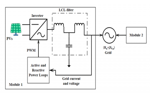
One of the new technologies are being developed to address the problems that modern power networks are facing is the synchronous inverter (also known as an inverter with virtual inertia). In essence, the synchronous inverter is used to mimic the behavior of the SGs. It is an inverter that converts a DC power source, see Figure 1. To reduce voltage and current ripple, three legs of the conventional inverter are modulated by pulse width modulation (PWM) linked to three LCL filters. Voltage ripple is disregarded as the synchronous inverter operates in parallel with the capacitors like an SGs. Moreover, module 1 in Figure 1 has two control loops [4].
The first one is the power loop which is responsible for forming the grid frequency. The second one is the reactive power loop which is responsible for regulating the grid voltage. The main problem in Figure 1 appears when the two synchronous inverters are connected to the grid. The absence of Synchronous Generators will reduce the grid inertia which could be compensated virtually by module 1 (at least).
Figure 1. A power system grid with two VSGs in parallel (module 1 and module 2)
As seen in Figure 1, there are two modules connected sequentially to the grid. Firstly, Module one is connected to the grid. After a while, the module two is synchronized with the grid. There are some assumptions that are assumed:
2.1 Virtual synchronous generator modelling
To mimic the behavior of synchronous generator, it should have control loop to regulate the amount of active and reactive power to generate the PWM of the inverter. Moreover, it is used to compensate the damping torque required for system stability in case of disturbance. The control circuit (not clarified her due to page limits, but see the study [4, 15]) uses the voltage and current from the grid to supply the suitable amount of active and reactive power to maintain the stability of the grid frequency and voltage.
The Grey Wolf Optimization algorithm is used to obtain the optimum parameters of the control loops which are the active power P, reactive power Q, the damping factor Dp, voltage drop factor Dq,voltage time constant τv, and frequency time constant τf. The control process of the VSG uses the model of the synchronous generator for stability purposes. Therefore, the control loop of active and reactive power for the VSG in the study [4] is used the same in the present work. The control loop of active power:
$J \frac{d^2 \theta}{d t^2}+D_p \frac{d \theta}{d t}=T_m-T_e$ (1)
where, $\theta=\omega t$. and w is the synchronous speed. J is the moment of inertia. Tm, Te is the mechanical and electrical torques respectively. It is clear from (1) that to obtain the stability in the system frequency (Which is related to angle $\theta$) the difference in the torques must equal to zero. This is given by:
$D_p=\frac{\Delta T_e}{\Delta f}$ (2)
where, Dp is the damping torque factor. This means the inverter should provide mechanical torque adequate to balance the electromagnetic torque introduced from the load demand and compensate for the inertia. The control loop of the active power is responsible for providing the damping torque to the system to restore the system frequency after a small disturbance and track the load demand. The control loop of reactive power is modelled depending on the equation of the induced voltage of the synchronous generator E that can be written as:
$E=k i_f \omega \sin \theta$ (3)
where, if is the field current, k is the machine constant that depends on the construction of the machine. The normalized induced voltage is employed in PWM of the synchronous inverter. In Figure 2, the GWO is used to find the optimal PID controller of the control loops. The optimal parameters are used to adjust the grid frequency to its standard range.
2.2 Grey Wolf Optimization
This method was introduced by Mirjalili et al. [33] in 2014. It simulates the social hunting behavior and hierarchy of the grey wolf. It is a Meta-heuristic optimization technique that uses the social hierarchy of grey wolf to model a mathematical system to solve the problems [33]. The problem solution is represented by three main solutions respectively, α which is the best solution, β which is the second fit solution, and δ which is the third best solution. The rest of the candidate solutions are represented by ω.
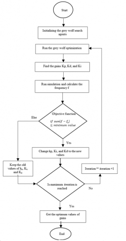
Figure 2. A grid connected of synchronous inverters with optimization steps
To find the optimum solution one should mimic the behavior of grey wolf by encircling the prey using the following equations:
$\vec{D}=\left|\vec{C} \cdot \overrightarrow{X_p}(t)-\overrightarrow{X_p}(t)\right|$ (4)
$\vec{X}(t+1)=\overrightarrow{X_p}(t)-\vec{A} \cdot \vec{D}$ (5)
where, A, B, and C are coefficients matrices. X is the position matrix of the grey wolf, and Xp is the position matrix of the prey. Both $\vec{A}$ and $\vec{C}$ are given by:
$\vec{A}=2 \vec{a} \overrightarrow{r_1}-\vec{a}$ (6)
And
$\vec{C}=2 \overrightarrow{r_2}$ (7)
where, omponents of a are linearly decreased from 2 to 0 over the course of iterations and r1, r2 are random vectors in [0, 1]. The search by the solution is carried out by updating the values of α, β, δ, and ω. i.e., changing the position matrix X. The candidate solutions converge from the prey when $|A|<1$.
The objective function of the grey wolf algorithm is used to minimize the deviation in the frequency. The grey wolf algorithm efficiently reduces the deviation and comes with good results through the process of optimization. The algorithm is carried out to extract the values of the PID controller gains, Kp, Ki, and Kd. The constraint is the minimum value of frequency deviation that govern the stability of the system. The values resulted from the optimization process is used in the system simulation to drive the system under the optimized values of the controller gains. The optimization process flow graph is seen in Figure 2.
The flow chart, Figure 2, shows how the GWO is used in conjunction with the control system to enhance the frequency to the best values and maintain it within boundaries, demonstrating how the optimization technique works. While monitoring the response frequency, the optimization technique will adjust the values of the control parameters, such as Kp, Ki, and Kd. It begins by selecting random values for Kp, Ki, and Kd. For each value selected, the simulation of the system is run, and the frequency response is measured. This response is then compared to the response from the previous iteration, and if necessary, the optimization technique selects these values for Kp, Ki, and Kd as the optimal values. and if not, it will retain the values from the previous iteration. The optimization will then preserve the best values of Kp, Ki, and Kd that produce the best objective value, which is the best frequency response, and continue changing the values of Kp, Ki, and Kd using the GWO optimization process until it achieves the ultimate iteration value.
The objective function of the optimization is written as:
$F=\sum\left|f-f_o\right|$ (8)
where, fo is the system normal frequency, f is the frequency resulted from the simulation, and F is the fitness value.
The system has been tested using MATLAB/Simulink. The system comprises of two inverters operated as VSM, power system grid, see Figures 1 and 2. The two inverters are connected to the grid after running the system. The two inverters’ parameters are listed in Table 1. The inverters ratings are 4 kVA, and they are supplied from a two separated DC voltage of 670V. The PWM operates at a switching frequency of 20kHz. The inverters are synchronized with a grid voltage of 400V Line-to-Line and 50Hz frequency.
Table 1. The inverters’ parameters
|
Variable |
Inverter 1 |
Inverter 2 |
|
Power rating |
4kVA |
4kVA |
|
DC voltage |
670V |
670V |
|
Switching frequency |
20kHz |
20kHz |
|
Output voltage |
400Vrms |
400Vrms |
|
Filter inductance |
5.2mH |
5.2mH |
|
Filter Capacitance |
1.5µF |
1.5µF |
|
Pset |
3.2kW |
1.6kW |
|
Qset |
2.4kVAR |
1.2kVAR |
|
Inertia |
4e-4 |
4e-4 |
|
Kp |
7.834 |
8.029 |
|
Ki |
9.058 |
9.336 |
|
Kd |
0.375 |
0.381 |
|
Modulation Index |
1 |
1 |
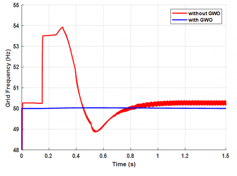
Figure 3. The frequency response of two systems under test. without optimization (dashed), with GWO (solid)
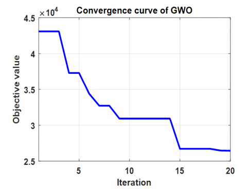
Figure 4. The convergence curve of GWO
Figure 3 depicts the frequency response (a grid frequency) of two tested systems. The red curve shows the grid frequency in case of parallel inverters without any optimization. In contrast to that, the blue curve shows the grid frequency when connecting two inverters in parallel with optimized PID parameters by using GWO. As seen from Figure 3, from time 0 to 0.15 the system runs without any synchronization. The grid frequency is slightly higher than the nominal value of 50Hz. Moreover, at time 0.15 sec, the two inverters are connected to the grid. At this time, the grid power suddenly changed. Therefore, the active power loop should adjust the grid frequency to its limit. Additionally, the frequency overshot is reduced from 8% down to 0% using GWO.
It is clear that the overshot without GWO is too high which triggers the protection system. Figure 4 shows the convergence of GWO. It can be seen that the used optimization method has an optimum solution after a number of iterations. The optimal values of the PID controller parameters are listed in Table 1.
This paper presents the parallel operation of synchronous inverters (inverters with virtual dampers or virtual Synchronous Generators) in the complete absence of Synchronous Generators in a power grid. The synchronous inverters have two control loops to adjust the grid frequency and the induced voltage. The PID controllers’ parameters are optimized using Gray Wolf Optimization (GWO).
The system is simulated by MATLAB/Simulink. The system is studied by synchronizing of two 4kVA synchronous inverters with power grid. Initially, the grid frequency has 8% overshot of its nominal value at the synchronization time. This will lead to an overall shutdown while this overshot will trigger the protection system. Due to employing GWO, the frequency response of the grid frequency is improved in case of parallel operation of the two synchronous inverters and virtual inertia. Moreover, the proposed system shows a 0% overshot in the grid frequency due to sudden change of the load (at the moment of synchronizing the inverters). The achieved results will encourage the researchers to synchronize more inverters with the power grid.
[1] Nayyar, Z.A., Zaigham, N.A., Qadeer, A. (2014). Assessment of present conventional and non-conventional energy scenario of Pakistan. Renewable and Sustainable Energy Reviews, 31: 543-553. https://doi.org/10.1016/j.rser.2013.12.049
[2] Magdy, G., Bakeer, A., Alhasheem, M. (2021). Superconducting energy storage technology-based synthetic inertia system control to enhance frequency dynamic performance in microgrids with high renewable penetration. Protection and Control of Modern Power Systems, 6: 1-13. https://doi.org/10.1186/s41601-021-00212-z
[3] Eriksson, R., Modig, N., Elkington, K. (2018). Synthetic inertia versus fast frequency response: A definition. IET Renewable Power Generation, 12(5): 507-514. https://doi.org/10.1049/iet-rpg.2017.0370
[4] Zhong, Q.C., Weiss, G. (2010). Synchronverters: Inverters that mimic Synchronous Generators. IEEE Transactions on Industrial Electronics, 58(4): 1259-1267. https://doi.org/10.1109/TIE.2010.2048839
[5] Beck, H.P., Hesse, R. (2007). Virtual synchronous machine. In 2007 9th International Conference on Electrical Power Quality and Utilisation, IEEE, 1-6. https://doi.org/10.1109/EPQU.2007.4424220
[6] Chandorkar, M.C., Divan, D.M., Adapa, R. (1993). Control of parallel connected inverters in standalone AC supply systems. IEEE Transactions on Industry Applications, 29(1): 136-143. https://doi.org/10.1109/28.195899
[7] Hussein, K.H., Muta, I., Hoshino, T., Osakada, M. (1995). Maximum photovoltaic power tracking: An algorithm for rapidly changing atmospheric conditions. IEE Proceedings-Generation, Transmission and Distribution, 142(1): 59-64. https://doi.org/10.1049/ip-gtd:19951577
[8] Kanellos, F.D., Tsouchnikas, A.I., Hatziargyriou, N.D. (2005). Micro-grid simulation during grid-connected and islanded modes of operation. In International Conference on Power Systems Transients, 6.
[9] Loix, T., De Brabandere, K., Driesen, J., Belmans, R. (2007). A three-phase voltage and frequency droop control scheme for parallel inverters. In IECON 2007-33rd Annual Conference of the IEEE Industrial Electronics Society, IEEE, pp. 1662-1667. https://doi.org/10.1109/IECON.2007.4460216
[10] He, Z.Y., Xing, Y. (2008). Distributed control for UPS modules in parallel operation with RMS voltage regulation. IEEE Transactions on Industrial Electronics, 55(8): 2860-2869. https://doi.org/10.1109/TIE.2008.918471
[11] Nandurkar, M.S.R., Rajeev, M.M. (2012). Design and simulation of three phase inverter for grid connected photovoltic systems. Proceedings of Third Biennial National Conference, pp. 80-83.
[12] Nardi, C., Stein, C.M.O., Carati, E.G., Costa, J.P., Cardoso, R. (2015). A methodology of LCL filter design for grid-tied power converters. In 2015 IEEE 13th Brazilian Power Electronics Conference and 1st Southern Power Electronics Conference (COBEP/SPEC), IEEE, pp. 1-5. https://doi.org/10.1109/COBEP.2015.7420101
[13] Mahafzah, K.A., Fraihat, H. (2021). Adaptive neuro fuzzy interface system based short circuit fault diagnoses in a three phase induction motor drive system. Universal Journal of Electrical and Electronic Engineering, 8(2): 35-40. https://doi.org/10.13189/ujeee.2021.080202
[14] Al-Hitmi, M.A., Moinoddin, S., Iqbal, A., Rahman, K., Meraj, M. (2019). Space vector vs. sinusoidal carrier-based pulse width modulation for a seven-phase voltage source inverter. CPSS Transactions on Power Electronics and Applications, 4(3): 230-243. https://doi.org/10.24295/CPSSTPEA.2019.00022
[15] Mahafzah, K.A., Rabab'ah, H., Al-Odienat, A., Almomani, M., Al-Maitah, K., Al-Mbaideen, A. (2022). The dynamic response of spwm vs. Svpwm synchronverter. Wseas Transactions on Power Systems, 93-102. https://doi.org/10.37394/232016.2022.17.11
[16] Rajlaxmi, E., Behera, S., Panda, S.K. (2020). Comparison of inverter control by spwm and svpwm method in standalone PV system. In 2020 IEEE International Symposium on Sustainable Energy, Signal Processing and Cyber Security (iSSSC), IEEE, pp. 1-6. https://doi.org/10.1109/iSSSC50941.2020.9358912
[17] Gözel, T., Hocaoglu, M.H. (2009). An analytical method for the sizing and siting of distributed generators in radial systems. Electric Power Systems Research, 79(6): 912-918. https://doi.org/10.1016/j.epsr.2008.12.007
[18] Muhammad, M.A., Mokhlis, H., Naidu, K., Franco, J.F., Illias, H.A., Wang, L. (2018). Integrated database approach in multi‐objective network reconfiguration for distribution system using discrete optimisation techniques. IET Generation, Transmission & Distribution, 12(4): 976-986. https://doi.org/10.1049/iet-gtd.2017.1134
[19] Jabr, R.A., Singh, R., Pal, B.C. (2012). Minimum loss network reconfiguration using mixed-integer convex programming. IEEE Transactions on Power Systems, 27(2): 1106-1115. https://doi.org/10.1109/TPWRS.2011.2180406
[20] Muqbel, A., Elsayed, A.H., Abido, M.A., Mantawy, A.A., Al-Awami, A.T., El-Hawary, M. (2019). Optimal sizing and location of solar capacity in an electrical network using lightning search algorithm. Electric Power Components and Systems, 47(14-15): 1247-1260. https://doi.org/10.1080/15325008.2019.1659456
[21] Prashant, Siddiqui, A.S., Sarwar, M., Althobaiti, A., Ghoneim, S.S. (2022). Optimal location and sizing of distributed generators in power system network with power quality enhancement using fuzzy logic controlled D-STATCOM. Sustainability, 14(6): 3305. https://doi.org/10.3390/su14063305
[22] Guha, D., Roy, P.K., Banerjee, S. (2016). Load frequency control of interconnected power system using Grey Wolf Optimization. Swarm and Evolutionary Computation, 27: 97-115. https://doi.org/10.1016/j.swevo.2015.10.004
[23] Shakarami, M.R., Davoudkhani, I.F. (2016). Wide-area power system stabilizer design based on Grey Wolf Optimization algorithm considering the time delay. Electric Power Systems Research, 133: 149-159. https://doi.org/10.1016/j.epsr.2015.12.019
[24] Pradhan, M., Roy, P.K., Pal, T. (2018). Oppositional based Grey Wolf Optimization algorithm for economic dispatch problem of power system. Ain Shams Engineering Journal, 9(4): 2015-2025. https://doi.org/10.1016/j.asej.2016.08.023
[25] Khalil, A., Alfaitori, K.A., Elbarsha, A. (2014). Stability analysis of parallel-inverters in microgrid. In 2014 20th International Conference on Automation and Computing, IEEE, 110-115. https://doi.org/10.1109/IConAC.2014.6935471
[26] Tan, K.T., Peng, X.Y., So, P.L., Chu, Y.C., Chen, M.Z. (2012). Centralized control for parallel operation of distributed generation inverters in microgrids. IEEE Transactions on Smart Grid, 3(4): 1977-1987. https://doi.org/10.1109/TSG.2012.2205952
[27] Hua, M., Hu, H.B., Xing, Y., Guerrero, J.M. (2012). Multilayer control for inverters in parallel operation without intercommunications. IEEE Transactions on Power Electronics, 27(8): 3651-3663. https://doi.org/10.1109/TPEL.2012.2186985
[28] Prodanovic, M., Green, T.C., Mansir, H. (2000). A survey of control methods for three-phase inverters in parallel connection. In 2000 Eighth International Conference on Power Electronics and Variable Speed Drives (IEE Conf. Publ.), IET, 475: 472-477. https://doi.org/10.1049/cp:20000293
[29] Yu, X.W., Jiang, Z.H., Zhang, Y. (2008). Control of parallel inverter-interfaced distributed energy resources. In 2008 IEEE Energy 2030 Conference, IEEE, 1-8. https://doi.org/10.1109/ENERGY.2008.4781030
[30] Sirisha, B. (2017). A study on islanded and parallel operation of inverters in a microgrid using droop control strategy. International Journal for Research in Applied Science and Engineering Technology, 5(3): 33-40. https://www.ijraset.com/fileserve.php?FID=6389.
[31] Hanaoka, H., Nagai, M., Yanagisawa, M. (2003). Development of a novel parallel redundant UPS. In The 25th International Telecommunications Energy Conference, INTELEC'03, IEEE, 493-498.
[32] Mohd, A., Ortjohann, E., Morton, D., Omari, O. (2010). Review of control techniques for inverters parallel operation. Electric Power Systems Research, 80(12): 1477-1487. https://doi.org/10.1016/j.epsr.2010.06.009
[33] Mirjalili, S., Mirjalili, S.M., Lewis, A. (2014). Grey wolf optimizer. Advances in Engineering Software, 69: 46-61. https://doi.org/10.1016/j.advengsoft.2013.12.007