Saadi I. Saadi* | Ibrahim K. Mohammed
© 2022 IIETA. This article is published by IIETA and is licensed under the CC BY 4.0 license (http://creativecommons.org/licenses/by/4.0/).
OPEN ACCESS
The main purpose of this paper is to obtain optimum power from a Photovoltaic (PV) panel and deliver it to a load system under standard irradiance and temperature weather conditions. Standard Boost DC-DC converters and bidirectional Buck-Boost DC-DC converters work as voltage controlling units for the power provided from the PV panel, which is used to charge the battery and supply suitable voltage signal to AC load. MPPT technique, based on two control algorithms, Particle swarm optimization (PSO) and Incremental Conductance (INC), is used to extract maximum power from the solar cells. Matlab/ Simulink environment is adopted to simulate the proposed PV power system. Simulation results are presented and analyzed based on transient and steady-state performance parameters. The performance results of the PV array system under the Standard Test Conditions (STC) showed that the INC-MPPT control algorithm can provide a more stable PV transient response, and a good steady-state PV response can be achieved using the PSO-MPPT control algorithm.
renewable energy, PV stand-alone system, solar PV panel, boost converter, off-grid
With the development of the world, the search for renewable energy continued not only popular with companies, but with the advancement of technology, ordinary people began to use it. Currently, approximately 26% of the world is powered by renewable energy [1]. Solar energy is a most widely renewable energy source due to the absence of fuel costs, minimal maintenance needs, and environmental friendliness [2]. In solar power system Photovoltaic (PV) model is used to convert the light and heat from the sun into electricity. PV model has gained significant attention in the last decades as it has no moving part, a companion to its environment and produces less pollution of the environment [3]. Improvements of PV solar cells have been continuing to increase their efficiency and accuracy and make them cheaper and more flexible. Development of power electronics and control approaches plays an essential role in the improvement of the PV solar power systems. The main electric parts of the PV solar energy system are power converters and inverters [4]. Power converters differ according to the principle of functioning, construction, energy efficiency, size, precision control, transitional state response, and price [5]. These electronic devices are mainly classified: Buck-Boost, Boost, Buck, Zeta, Sepic, and Cuk converters [6]. The converters are more power-efficient devices due to their high voltage conversion efficiency, which reaches to 98%. In solar power systems, the power converters are used to regulate the PV output voltage and supply a suitable voltage to DC load. Type and number of power converters used in the solar energy system is governed by the system application. Maximum Power Point Tracking (MPPT) technology is used to extract maximum power from PV panel. MPPT is implemented using one of the optimization algorithms like Incremental Conductance (INC) and Practicles Swarm Optimization (PSO) algorithms and Perturb& Observe (P&O) which are adopted to tune the duty cycle of the Pulse Width Modulation (PWM) command signal used to control the switching process of the power converter circuit.
The second part of the PV power system, voltage inverters, are used to connect PV cells by on-grid and off-grid system and provide the load by an AC voltage. It is worth considering that the converters and inverter circuits are non-linear systems. Generally, classic and optimal linear controllers like PID and LQR controller respectively are used successfully to implement control action of more nonlinear systems within an acceptable operating space [7-10]. PID controller is highly recommended to implement the control action of various industrial applications due to its simplicity and easy to realize [11]. In this study, a linear PID controller can be adopted to perform a voltage regulation process of the DC/DC converters and DC/AC inverter circuits in the proposed PV power system as the variation of the input voltage of these circuits is not huge. While for massive variation input voltage power systems, PID linear control system may not give an acceptable voltage regulation performance, for this type of systems a non-linear controller technique is recommended to control its output voltage.
In order to improve the performance of the PV power system, the parameters of the MPPT control and the converter controller should be tuned properly. A classic tuning approach using trial and error method can be used to improve the performance of the voltage control system. However, this manual tuning approach consumes more time and effort [12]. Moreover, there is no guarantee that the system based on the tuned parameters can achieve best performance. To avoid the drawbacks of the manual tuning approach, many intelligent optimization methods; Genetic Algorithm (GA) [13, 14], Fuzzy Logic (FL) [15], Big Bang-Big Crunch (BBBC) algorithm [16], Bacterial Foraging Optimization (BFO) algorithm algorithm [17, 18], Particle Swarm Optimization (PSO) algorithm [19, 20] and Artificial Bee Colony (ABC) [21, 22] are successfully used by many researchers to optimize the PID controller in various control problems. In this application, a PSO tuning method is used to obtain best values for the system control parameters, as it has a simple procedure, a rapid convergence speed and easy to implement. Furthermore, its ability to find a global solution for the power system problem. During the past decades there is a considerable interest in development of the solar energy systems. Jadhav et al. [23] express a hybrid renewable energy system based on PV and wind with battery storage is presented for grid connection. A solar cell and wind turbine are employed to power on and off grid link and charging a battery bank. A Boost converter is used to match between PV-wind-battery system and grid connection. PI controller is adopted to regulate the output voltage of the DC-DC boost converter. In this study, the energy generated by solar array and wind turbine is managed by a control unit so that an effective power is supplied to battery bank, autonomous grid, off-grid and load. The proposed hybrid power system is simulated using Matlab/Simulink environment and its output responses are analysed to confirm the efficiency of the suggested power generation and management method.
The authors in the reference [24] presented power system supplied by solar panels and batteries for stand-alone and on-grid connections. They introduced solar inverter which integrates PV array, battery, grid and DC load using Fuzzy control approach. The role of Fuzzy Logic (FL) controller is to determine the amount of power that each source should supply to DC-rail. Based on the proposed FL control approach, the PV panel operates in ON/OFF MPPT, which help operate the inverter in stand-alone mode. A Boost converter is used to adjust the output voltage of solar panel that should supply to DC load and AC load through inverter. The researchers proposed the MPPT technique to get the maximum power supplied to loads based on FL method. Based on the connection strategy between panel, battery and grid, the performance of the proposed power system is tested and evaluated under seven connection modes. The simulation results proved that the proposed control system could manage an intelligent power flow between the sources.
Seguel et al. [25] used Buck and Buck-Boost converter to convert energy from solar panels to load. The researchers compared the performance of three methods of MPPT to obtain maximum power from PV, using incremental conductance, perturb and observe, and constant voltage. The proposed method was confirmed by simulation using MATLAB/Simulink. Simulation results obtained from the PV system operating under temperature and various radiation conditions are compared and discussed. The INC--Buck combination had the highest steady-state efficiency while the PV-Buck-Boost combination showed the best transient behavior.
In 2021, Rinku et al. [26] proposed a renewable power system for resistive load based on a PV array using MPPT controller with Boost converter. In this study, the MPPT controller is implemented using modern PSO algorithm and the traditional algorithms, INC and P&O, which are used to extract maximum power of the PV panel under constant solar insolation and temperature conditions. The proposed system is simulated using Matlab/Simulink software to test the performance of the presented PSO/INC/P&O-MPPT controllers. The response of average power extracted from PV panel and the output voltage across the load using PSO, INC and P&O algorithms are evaluated based on rise time, settling time and overshoot, parameters. The simulated results showed that the presented PSO-MPPT controller can enhance the power efficiency of the PV panel system and achieve more accurate and faster response compared with the standard algorithms.
In 2021, Koson et al. [27] proposed a modified solar power system based on non-iterative MPPT control for single phase off-grid connection. The PV power is delivered to the grid system through a single-stage single-phase inverter circuit. The power converter circuit of the system is modified to implement open circuit voltage V_oc and short circuit current I_sc measurements of the PV array. The non-iterative MPPT is designed to realize the maximum power of the PV panel using the datasheet parameters of the PV panel combined with the V_oc and Isc measurements. In the study, a double band hysteresis current controller is used to regulate the output current of the inverter circuit based on the current reference. The system based on non-iterative MPPT control algorithm is simulated using Matlab/Simulink tool. The simulation results in transient and steady state domains are analysed to evaluate the performance of the proposed system. The simulated test confirmed that under changing irradiance working conditions the presented power system can transfer maximum power from the PV panel to the off-grid system with 〖THD〗_i of 2.9% and PF of 0.95. In this paper, an off-grid interface PV system based on a Boost converter is also presented. Two control methods, PSO and INC, are adopted to implement the MPPT technique for the PV panel system. MPPT is based on the INC and PSO control method is used to track maximum power generated from the photovoltaic array to the load system. A bidirectional Buck-Boost converter is utilized to charge the battery by full power and discharge its power to DC loads to enhance the power delivered to the load system. The rest of the paper is organized as follows; the configuration and mathematical modelling of the proposed PV power system are given in section 2. Optimization algorithms are presented in Section 3. Section 4 introduces the theory of the PID controller technique of the system. In section 5, Simulation results PV power system., followed by concluding remarks in section 6.
2.1 PV cell model
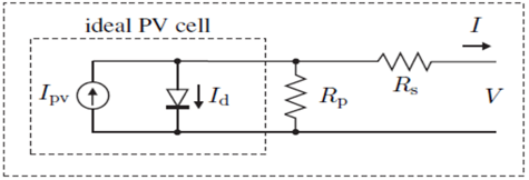
Essentially, the amount of energy generated by a photovoltaic system depends on its environmental and operating parameters. A photovoltaic system's effectiveness depends on temperature, solar radiation, and variations in sunshine and shadow [28]. The single-diode model is adopted to simulate the PV cell model. The equivalent electric circuit of the PV cell is presented in Figure 1. The current equation of the PV cell is given below:
$I_{p v}=I_{p h}-I_D-I_{s h}$ (1)
where, $I_{p v}$ is the current of PV cell (A), $I_{p h}$ is the light generated current (A), $I_D$ is the reverse saturation current flowing through the diode (A), $I_{s h}$ is the current flowing through the internal shunt resistance $R_{s h}$(A).
$I_{p h}=\left[I_{S C}+K *\left(T-T_{S T C}\right)\right] * \frac{G}{G_{S T C}}$ (2)
where, $I_{S C}$ is short circuit current of the PV cell (A), K is Bolzmann constant $1.38 * 10^{-23}\left(\frac{N m}{K}\right)$, T is the PV model temperature in Kelvin, G is solar irradiance ( $\left(\mathrm{W} / \mathrm{m}^2\right)$ and $T_{S T C}$ and $G_{S T C}$ are the PV module temerature an irradiance at STC. Based on the above equation, it is clear that as the PV module temperature increases, its light generated current increases too, solar irradiance decreases, while the PV module output voltage decreases as well.
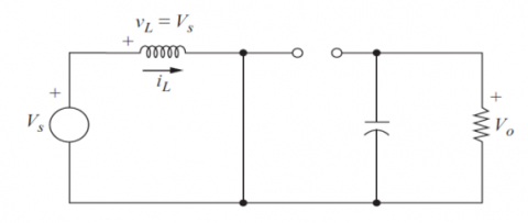
2.2 Boost converter model
In this study, a DC-DC Boost converter is implemented between the PV panel and the load unit. It is used to step up the output voltage of the PV panel to suitable value for the load. The electric circuit of the DC-DC Boost converter is shown in Figure 2.
Figure 1. Photovoltaic cell equivalent circuit
Figure 2. Boost converter electric circuit
Boost Converter switching modes
Switch ON mode
The electric circuit of the voltage converter in ON switching state is presented in Figure 3. Using Kirchhoff's voltage law:
Figure 3. Boost equivalent circuit for the ON switch state
$V_s=V_L=L \frac{d i_L}{d t}$ (3)
$I_c=C \frac{d V_c}{d t}$ (4)
$\frac{d V_C}{d t}=\frac{I_C}{C}=\frac{V_C}{R C}$ (5)
Assume the states of the DC-DC Boost converter system are as follows:
$x_1(t)=i_L , \dot{x_1}(t)=\frac{d i_L}{d t}$, $x_2(t)=V_c, \dot{x_2}(t)=\frac{d V_c}{d t}$ and $u(t)=V_s$
Based on the above assumption, Eqns. (3) and (5) can be written as follows:
$\dot{x_1}(t)=\frac{u(t)}{L}$ (6)
$\dot{x}_2(t)=\frac{x_2(t)}{R C}$ (7)
$\dot{x_1}(t)=0 x_1(t)+0 x_2(t)+\frac{u(t)}{L}$ (8)
$\dot{x_2}(t)=0 x_1(t)+\frac{1}{R C} \ x_2(t)+0 u(t)$ (9)
Based on Eqns. (8) and (9), the state space representation of the Boost converter is given below:
$\dot{x}(t)=A_1 x(t)+B_1 u(t)$ (10)
$y(t)=C_1 x(t)+D u(t)$ (11)
where, $A_1=\left[\begin{array}{cc}0 & 0 \\ 0 & \frac{1}{R C}\end{array}\right]$, $B_1=\left[\begin{array}{l}\frac{1}{L} \\ 0\end{array}\right]$, $C_1=\left[\begin{array}{ll}0 & 1\end{array}\right]$ and $D=0$.
Switch OFF mode
Figure 4 shows the electric circuit of the Boost converter system in OFF switching state.
Figure 4. Boost circuit in OFF switch mode
Using Kirchhoff's voltage law:
$V_s=v_L+v_C$ (12)
$V_s=L \frac{d i}{d t}+v_C$ (13)
$v_c=v_R$ (14)
$i_L=i_c+i_R$ (15)
$i_L=C \frac{d V_c}{d t}+\frac{V_c}{R}$ (16)
Eqns. (13) and (16) can be written as follows:
$\dot{x_1}(t)=\frac{u(t)}{L}-\frac{\ x_2(t)}{L}$ (17)
$\dot{x}_2(t)=\frac{x_{1(t)}}{C}-\frac{x_2(t)}{R C}+0 u(t)$ (18)
Based on Eqns. (17) and (18), the state space representation is given by:
$\dot{x}(t)=A_2 x(t)+B_2 u(t)$ (19)
$y(t)=C_2 x(t )+D u(\mathrm{t})$ (20)
where, $A_2=\left[\begin{array}{cc}0 & -\frac{1}{L} \\ \frac{1}{C} & -\frac{1}{R C}\end{array}\right], B_2=\left[\begin{array}{l}\frac{1}{L} \\ 0\end{array}\right], C_2=\left[\begin{array}{ll}\ 0 & 1\end{array}\right]$ and $D=0$.
State Space Averaging Technique
This technique is used to formulate the state space representation of the Boost converter circuit based on both switching states (ON and OFF) of the MOSFET electrical device of the converter. In this study, the general state space model of the DC-DC Boost converter system is formulated by state-space averaging technique as follows:
$\dot{x}(t)=A x(t)+B u(t)$ (21)
$y(t)=C x(t)+D u(t)$ (22)
where, $C=C_1=C_2$,
$A=A_1 d+A_2(1-d)$ (23)
$B=B_1 d+B_2(1-d)$ (24)
Based on (10) and (19), the state and input matrices of the Boost converter become:
$\begin{aligned} A=\left[\begin{array}{cc}0 & 0 \\ 0 & -\frac{1}{R C}\end{array}\right] d & +\left[\begin{array}{cc}0 & -\frac{1}{L} \\ \frac{1}{C} & -\frac{1}{R C}\end{array}\right](1-d)=\left[\begin{array}{cc}0 & -\frac{1-d}{L} \\ \frac{1-d}{C} & -\frac{1}{R C}\end{array}\right]\end{aligned}$ (25)
$B=\left[\begin{array}{l}\frac{1}{L} \\ 0\end{array}\right] d+\left[\begin{array}{l}\frac{1}{L} \\ 0\end{array}\right](1-d)=\left[\begin{array}{c}\frac{1}{L} \\ 0\end{array}\right]$ (26)
Based on Eqns. (25) and (26), the state and output equations of the converter Eqns. (21) and (22) are written as below:
$\left[\begin{array}{l}x_1(t) \\ x_2(t)\end{array}\right]=\left[\begin{array}{cc}0 & -\frac{(1-d)}{L} \\ \frac{(1-d)}{C} & -\frac{1}{R C}\end{array}\right]\left[\begin{array}{l}x_1(t) \\ x_2(t)\end{array}\right]+\left[\begin{array}{l}\frac{1}{L} \\ 0\end{array}\right] u(t)$ (27)
$y(t)=[0 \ 1]\left[\begin{array}{l}x_1(t) \\ x_2(t)\end{array}\right]+[0] u(t)$ (28)
3.1 MPPT technique
The purpose of using the MPPT technology is to obtain maximum power from the solar panel system. Based on sufficient irradiation and suitable temperature, the solar system can produce maximum power effectively if an appropriate MPPT algorithm is applied [29]. In MPPT technique process, the PV module operating voltage is moved to maximum power point operating regan under changing weather conditions. Maximum power can transfer from PV module to load can be achieved through MPPT algorithm by a suitable adjustment for the control signal duty cycle of the Boost’s MOSFET device. Academics and industry professionals have developed many MPPT algorithms to achieve maximum power transfer from the PV panel to the load. such as P&O, INC, Additive Conduction (AC), Parasitic Capacitance (PC), Constant Voltage (VC) method, Neural Network Control (NNC), PSO and Vagus Control [1]. In this work, a classic INC and modern PSO algorithms are adopted to the implement MPPT process.
3.2 INC-MPPT method
The INC method is based on finding the direction of change in the terminal voltage of solar modules by measuring and comparing their incremental and instantaneous conductance. The output power grows linearly with the solar modules' terminal voltage ($\frac{d_p}{d_v}>0$). The output power drops linearly as the terminal voltage increases ($\frac{d_p}{d_v}>0$), and the operational point is ($\frac{d_p}{d_v}=0$) [2] as in the Figure 5.
Figure 5. Flowchart of INC-based MPPT algorithm
3.3 PSO MPPT method
The proposed power system is also based on the PSO tuning algorithm. The PSO method is a meta heuristic technique developed by Eberhart and Kennedy in 1995. The foraging behavior of birds and fish is the main idea for this algorithm. The probability of finding the optimum solution gets faster with high tracking efficiency due to the fast response of particles (fish or birds). In this application, PSO algorithm can provide an excellent global solution for PV power system problems due to its ability to accelerate the rate of convergence and improve the solution accuracy. The basic idea of the PSO algorithm is to reach the optimum solution, which is based on the superlative between the solutions obtained by the individuals. It can avoid the local solutions through the right setting for the inertia weight value of the PSO algorithm. During the PSO implementation process, the individuals that provide current solutions and don’t minimize the error cost function will be ignored. This action will definitely support the convergence operation to optimum solution, and hence getting fast and high accuracy global solution.
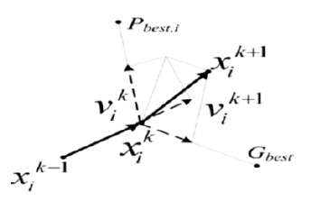
Each particle is navigating in the search space and has its location and velocity. It has been updated in every iteration. Each particle is issued as $P_{\text {best }}$, and the best particle among them is issued as $G_{\text {best }}$. Figure 6 shows the particles movement in the search space [30].
Figure 6. Movement of particles in the search space
The flow chart of the PSO algorithm is shown in Figure 7. The equations for velocity and distance update for each particle are given below:
$V_i(K+1)=w \cdot V_i(K)+c_1 r_1\left(P_{\text {best }}-x_i(K)\right)+c_2 r_2\left(G_{\text {best }^{\mathrm{}}}-x_i(K)\right)\left.x_i(K+1)=x_i(K)+V_i(K+1)\right)$ (29)
where, $x_i$ and $v_i$ are the location and velocity of particle respectively, $r_1$ $r_2$ are random numbers between [0,1], i is the number of iterations, $\mathrm{c}_1, \mathrm{c}_2$ are cognitive and social coefficient respectively, w is the inertia weight and $\mathrm{N}_{\mathrm{p}}$ is the number of particle.
Figure 7. Flowchart of PSO-based MPPT algorithm
In this application, a classic PID controller is utilized to regulate the output voltage of the bidirectional Buck-Boost converter and inverter circuit with known parameters, the PID controller, is the most often used control technology for various industrial engineering applications. The PID controller is also called a "three-term" controller because it combines integral, proportional, and differential control. The controller's standard time structure is:
$u(t)=K_p e(t)+K_i \int_0^t e(\tau) d t+K_d \frac{d e(t)}{d \tau}$ (30)
where, $u(t)$ represents the controller command signal operating on the error signal $e(t)$ ), and $\mathrm{K}_{\mathrm{p}}$, $\mathrm{K}_{\mathrm{i}}$, and $\mathrm{K}_{\mathrm{d}}$ represent the integral, proportional, and derivative gains, respectively. Using the Laplace transform of the above equation, the controller's s-domain transfer function is as follows:
Figure 8. Simulink model of PV-Boost system
$G_{P I D}=\frac{U(s)}{E(s)}=\frac{K_d s^2+K_p s+K_i}{s}$ (31)
In this research, the proposed PV power system based on MPPT control technique is used deliver voltage to AC and DC loads and to charge a battery storage system. The proposed PV power system is simulated using MATLAB/Simulink-2018a environment, version 9.4 with variable step solver (ode23t(mod.stiff/Trapezoidal). The PV panel consists of one parallel string; each string has two solar cells connected in series with a maximum power of 480W. In this application, a Boost converter is used to increase the output voltage level of the PV panel from 61V to at STC to 320V. The voltage conversion process of the converter is governed by the PWM command signal generated from the MPPT algorithm.
MPPT algorithm is mainly utilized to obtain the maximum power of the solar array that can be transferred to the load. In this study, PSO and INC algorithms are utilized to implement the MPPT process. These algorithms are used to find an optimum duty cycle of PWM signal used to drive the Boost converter under varying solar irradiance and ambient temperature. In this study, a 100Ah, 12V lead-acid battery is used as a storage power unit. It is connected to a DC-DC bidirectional Buck-Boost regulator for charging and discharging purposes. PI controller is used to control the charging and discharging processes of the battery. In the proposed system, the output of the Boost converter is fed to an inverter circuit, which is employed to supply an off-grid AC load system by 220V/50Hz voltage signal. The proposed PV system is simulated based on two working scenarios under the system parameters stated Table 1. The first scenario test is conducted based on INC-MPPT technology, the second scenario is implemented using PSO-MPPT technology.
5.1 Simulation of INC-MPPT based PV system
PV-Boost Response
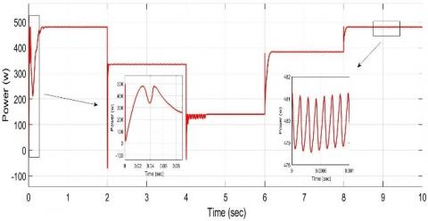
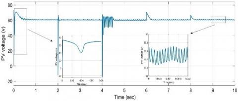
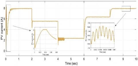
Figure 8 shows the Simulink diagram of the presented PV panel system with INC-MPPT algorithm. The output power response of the PV array with a temperature of 25℃ and solar irradiance sequence of (1000, 700, 300, 800, and 1000) $\mathrm{W} / \mathrm{m}^2$ during a response time of 10 seconds with a change time of (2, 4, 6 and 8) seconds is shown in Figure 9. Based on solar radiation of 1000 $\mathrm{W} / \mathrm{m}^2$, the PV panel voltage and current response are shown in Figure 10 and 11 respectively. At the same irradiation value and based on Figures 9-11 the output power of the PV system is about 466.4 W and the corresponding PV voltage and current values are 64.72V and 7.206 A respectively. Based on Eq. (5), the power efficiency of the system is 28.79%.
Table 1. Electrical parameters of Boost converter
|
Parameters |
Value |
|
Input voltage($V_{i n}$) |
66 V |
|
output voltage($V_{\text {out }}$) |
320 V |
|
PV- capacitor ($C_1$) |
5.9942e-05 F |
|
Capacitor Boost ($C_2$) |
1.4355e-05 F |
|
Inductance (L) |
0.1940 H |
|
Frequency (f) |
7200 Hz |
Figure 9. Output power response of INC-MPPT
Figure 10. Output voltage response of INC-MMPT based PV panel
Figure 11. Output current response of INC-MPPT based PV panel
Figure 12. Boost output voltage response with the INC-MPPT algorithm
Table 2. PID gain Parameters for bidirectional converter
|
Parameters |
Value |
|
$\mathrm{K}_{\mathrm{p} 1}$ |
0.7 |
|
$\mathrm{K}_{\mathrm{I} 1}$ |
18.1818 |
|
$\mathrm{K}_{\mathrm{D} 1}$ |
0 |
|
$\mathrm{K}_{\mathrm{P} 1}$ |
12.930 |
|
$\mathrm{K}_{\mathrm{T} 2}$ |
13.071 |
|
$\mathrm{K}_{\mathrm{D} 2}$ |
0 |
Table 3. PID gain parameters for DC/AC inverter
|
Parameters |
Value |
|
$\mathrm{K}_{\mathrm{p} 1}$ |
0.0285 |
|
$\mathrm{K}_{\mathrm{I} 1}$ |
20 |
|
$\mathrm{K}_{\mathrm{D} 1}$ |
0 |
|
$\mathrm{K}_{\mathrm{P} 1}$ |
29 |
|
$\mathrm{K}_{\mathrm{T} 2}$ |
6.67 |
|
$\mathrm{K}_{\mathrm{D} 2}$ |
0 |
Under a reference voltage of 320 V and the same radiation varying sequence, the output voltage response of the Boost converter is presented in Figure 12. It can be noted from Figure 12 that, the INC-MPPT algorithm showed a fast transient response with rising time of approximately 0.015 s and a maximum overshoot of 89% and faced the radiation change effect in the performance of the system effectively.
In steady state mode, the Boost converter produced an output DC voltage that fluctuated about 320.9 V with an oscillation of 7% during the time period of (4-6) s while through the rest of the run time period of the system, the oscillation is within an acceptable range (approximately 1%). The high oscillation in the system response during the period (4-6) s belongs to the low power generated from the PV panel due to the low value of the incident radiation.
BSS Response
In the proposed power system, the battery is charged by the output DC voltage of the Boost converter during the sunshine day hours and discharged its power in the night to the load in order to ensure continuous supply the power to the load over the time. In this study, the current and the voltage of the battery are controlled based on the SOC parameter.
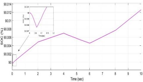
In this application, the initial value of the SOC parameter for the battery is set to 90%. At the begin of the system operation, the battery at transient response works at discharging mode so its SOC parameter decreases as the delivered power from the PV panel through the Boost converter is not enough to charge the battery. After finishing the transient period, the output voltage of the Boost converter increases to a value enables the battery to work in charging mode, hence its SOC status will be increased linearly as shown in Figure 13.
Inverter Response
In this study, the inverter is designed to invert the output voltage of the Boost converter from 320V DC to 220V AC with a frequency of 50 Hz and efficiency of 98% as shown in Figure 14. For this reason, a LCL filter circuit is included into the output of the inverter to sort out the oscillation problem in the output signal. Figure 15 present voltage output response of the inverter with the LCL filter.
Figure 13. SOC response of the battery based on the INC-MPPT algorithm
Figure 14. Voltage response of the inverter using INC-MPPT algorithm
Figure 15. Voltage response of the inverter load using INC-MPPT algorithm
5.2 Simulation of PSO-MPPT based PV system
PV-Boost Response
The Simulink model of the PV power system based on PSO-MPPT algorithm is the same as that in the INC-MPPT based PV system stated in Figure 8, except for the PSO block instead of the INC block. The duty cycle obtained by the PSO algorithm is approximately 0.8098 at which maximum solar power is transferred from the PV panel to the load unit. Under the same working circumstances regarding temperature and radiation sequense, the output power response of the PV panel is shown in Figure 16. Figure 17 and 18 show the voltage and current responses of the PV panel based the PSO-MPPT algorithm respectively. Based on Figures 16-18, the maximum power obtained from the PV array under solar irradiation of 1000W/m2 and a temperature of 25C is 481.8W, and the steady state PV voltage and current values are 61.01V and 7.896 A respectively. Based on Eq. (5), the power efficiency of the PV panel is 29.74%.
Figure 16. Output power response of PV system based on PSO-MPPT algorithm
From the PV system response stated in Figure 9 and 16, it is obvious that the PV power system based on the PSO-MPPT algorithm under varying solar radiation achieved a better steady-state response and higher power efficiency compared with that of the INC-MPPT algorithm. However, in the transient response mode, the PV power system based on the INC approach can achieve a faster transient response compared with that of the PSO tuning method.
Figure 17. Output voltage response of PV system based on PSO-MPPT algorithm
Figure 18. Output current response of PV system based on PSO-MPPT algorithm
Based on a demand voltage of 320 V and under the same radiation varying sequence, Figure 19 shows the output voltage response of the Boost converter. It can be noted from the minplot of Figure 19 that, the PSO-MPPT algorithm showed a fast transient response with a rise time of 0.18 s and maximum overshoot of 78% and faced the radiation change effect in the performance of the system efficiently. In steady state time response domain, the Boost converter provides an output DC voltage that fluctuated about 321.2V with an oscillation approximately of 25% at the start of the time period (4-6) s and approximately of 5% during the remain time of the period (4-6) s while through the rest run time period of the system the oscillation is reduced to approximately of 0.6%.
Figure 19. Boost output voltage with PSO-MPPT algorithm
Based on Figures 12 and 19, it is clear that the Boost converter based on the PSO-MPPT technique appeared lower overshoot response and smaller fluctuation around the steady state voltage compared with that of the INC-MPPT algorithm.
BSS Response
Based on the same charging and discharging procedure applied in the BSS of INC-MPPT, Figure 20 shows the SOC behavior of the battery system based on PSO-MPPT algorithm.
Figure 20. SOC response of battery based on PSO-MPPT approach
Comparing between the responses presented in Figure 13 and 20, it can be noted that based on the PSO-MPPT algorithm, the charging value of the battery droped from its initial value 90% to a value of 89.99982, while with the INC algorithm, the charging state is droped to a value of 89.99975. In addition, the charging level of the BSS based on the PSO-MPPT method is higher than that based on the INC_MPPT tuning approach.
It is worth considering that the inverter response of the power system is the same response for the inverter circuit using the INC -mppt algorithm.
Based on the results obtained from the proposed PV power system under the action of INC/PSO-MPPT algorithm, it can be said that the MPPT technique used to extract maximum power from PV module is applied successfully through providing a fast transient and stable PV output power response using INC algorithm and a low fluctuation PV power based on PSO algorithm under changing atmosphere conditions.
This paper presents an off-grid PV panel system to charge the battery system and provide power to the AC load. Two control methods, PSO and INC algorithms are adopted to implement the MPPT technique. These algorithms were used to extract maximum PV power and send it to the load system through the Boost converter circuit. The PSO-MPPT and INC-MPPT tuning systems are proposed to generate optimum PWM signals with a variable duty cycle, which are used to drive the MOSFET switching unit of the Boost converter. The stand-alone PV power system is simulated using Matlab/Simulink software to evaluate the performance of the proposed PSO/INC-MPPT control algorithm. Simulation results have shown that, under STC, the PSO-MPPT control algorithm can improve the transient response of the power and charging speed of the battery, while the INC-MPPT control algorithm can support the steady-state response of the PV panel system by providing a stable and high-level power signal.
|
W |
Inertia weight. |
|
$c_1, c_2$
|
Cognitive and social coefficient respectively |
|
$i$ |
Number of iterations |
|
$r_1, r_2$ |
Random numbers between [0,1] |
|
$v_i$ |
The velocity of the particle |
|
$I_{\mathrm{D}}$ |
Diode current (A) |
|
$I_{\mathrm{ph}}$ |
Photo generated current (A) |
|
$R_s$ |
Series Resistance of PV cell |
|
$R_{\mathrm{sh}}$ |
Shunt Resistance of PV cell |
[1] Baba, A.O., Liu, G., Chen, X. (2020). Classification and evaluation review of maximum power point tracking methods. Sustainable Futures, 2: 100020. https://doi.org/10.1016/j.sftr.2020.100020
[2] Babaa, S.E., El Murr, G., Mohamed, F., Pamuri, S. (2018). Overview of boost converters for photovoltaic systems. Journal of Power and Energy Engineering, 6(4): 84197. https://doi.org/10.4236/jpee.2018.64002
[3] Elbaksawi, O. (2019). Design of photovoltaic system using buck-boost converter based on MPPT with PID controller. Universal Journal of Electrical and Electronic Engineering, 6(5): 314-322. http://dx.doi.org/10.13189/ujeee.2019.060502
[4] Musyafa, A., Gustawan, I.R., Asy, M.K., Rahmadiansyah, A.N.R.D., Noriyati, R.D. (2017). Development of power electronics, buck boost converter, based PI-PID control on horizontal wind turbine generation, for low rate wind speed analysis and reporting. Australian Journal of Basic and Applied Sciences, 17(11): 79-87.
[5] Almawlawe, M., Kovandžić, M. (2020). Modified ziegler–nichols method for tuning a pid controller of buck-boost converter. BUCK-BOOST.
[6] Gupta, A.K., Kumar, D., Reddy, B.M., Samuel, P. (2017). BBBC based optimization of PI controller parameters for buck converter. In 2017 Innovations in power and advanced computing technologies (i-PACT), Vellore, India, pp. 1-6. https://doi.org/10.1109/IPACT.2017.8244983
[7] Mohammed, I.K., Sharif, B.S., Neasham, J.A., Giaouris, D. (2011). Novel MIMO 4-DOF position control for Capsule Endoscope. In 2011 IEEE International Symposium of Circuits and Systems (ISCAS), Rio de Janeiro, Brazil, pp. 909-912. https://doi.org/10.1109/ISCAS.2011.5937714
[8] Mohammed, I.K., Abdulla, A.I. (2020). Elevation, pitch and travel axis stabilization of 3DOF helicopter with hybrid control system by GA-LQR based PID controller. International Journal of Electrical and Computer Engineering, 10(2): 1868-1884. https://doi.org/10.11591/ijece.v10i2.pp1868-1884
[9] Mohammed, I.K., Abdulla, A.I. (2020). Balancing a segway robot using LQR controller based on genetic and bacteria foraging optimization algorithms. TELKOMNIKA (Telecommunication Computing Electronics and Control), 18(5): 2642-2653. https://doi.org/10.12928/TELKOMNIKA.v18i5.14717.2642
[10] Daware, A.V., Sabnis, A. (2018). Performance measurement of linear and non linear controllers for buck-boost converter in solar energy system. In 2018 International Conference on Computation of Power, Energy, Information and Communication (ICCPEIC), Chennai, India, pp. 225-229. https://doi.org/10.1109/ICCPEIC.2018.8525210
[11] Mohammed, I., Sharif, B., Neasham, J. (2012). Design and implementation of a magnetic levitation control system for robotically actuated capsule endoscopes. In 2012 IEEE International Symposium on Robotic and Sensors Environments Proceedings, Magdeburg, Germany, pp. 7-12. https://doi.org/10.1109/ROSE.2012.6402614
[12] Abdulla, A., Mohammed, I., Jasim, A. (2017). Roll control system design using auto tuning LQR technique. International Journal of Engineering and Innovative Technology, 7(1): 10-17.
[13] Ou, C., Lin, W. (2006). Comparison between PSO and GA for parameters optimization of PID controller. In 2006 International conference on mechatronics and automation, Luoyang, China, pp. 2471-2475. https://doi.org/10.1109/ICMA.2006.257739
[14] Cheng, C.H., Cheng, P.J., Xie, M.J. (2010). Current sharing of paralleled DC–DC converters using GA-based PID controllers. Expert Systems with Applications, 37(1): 733-740. https://doi.org/10.1016/j.eswa.2009.05.083
[15] Sonmez, Y., Ayyildiz, O., Kahraman, H.T., Guvenc, U., Duman, S. (2015). Improvement of buck converter performance using artificial bee colony optimized-PID controller. Journal of Automation and Control Engineering, 3(4): 304-310. https://doi.org/10.12720/joace.3.4.304-310
[16] Gupta, A.K., Kumar, D., Reddy, B.M., Samuel, P. (2017). BBBC based optimization of PI controller parameters for buck converter. In 2017 Innovations in power and advanced computing technologies (i-PACT), Vellore, India, pp. 1-6. https://doi.org/10.1109/IPACT.2017.8244983
[17] Jalilvand, A., Vahedi, H., Bayat, A. (2010). Optimal tuning of the PID controller for a buck converter using bacterial foraging algorithm. In 2010 International Conference on Intelligent and Advanced Systems, Kuala Lumpur, Malaysia, pp. 1-5. https://doi.org/10.1109/ICIAS.2010.5716105
[18] Regis, D.M.S., Kumar, S.P., Devadhas, G.G. (2011). An optimum setting of controller for a dc-dc converter using bacterial intelligence technique. In ISGT2011-India, Kollam, India, pp. 204-210. https://doi.org/10.1109/ISET-India.2011.6145383
[19] Hekimoğlu, B., Ekinci, S. (2020). Optimally designed PID controller for a DC-DC buck converter via a hybrid whale optimization algorithm with simulated annealing. Electrica, 20(1): 19-27. https://doi.org/10.5152/electrica.2020.19034
[20] Ahmed, M.N., Mohammed, I.K., Younis, A.T. (2021). Design and implementation of PSO/ABC tunned PID controller for Buck converters. Periodicals of Engineering and Natural Sciences (PEN), 9(4): 643-656. http://dx.doi.org/10.21533/pen.v9i4.2411
[21] Mohammed, I.K. (2021). Design of optimized PID controller based on ABC algorithm for buck converters with uncertainties. Journal of Engineering Science and Technology, 16(5): 4040-4059.
[22] Mohammed, I.K., Abdulla, A.I. (2018). Design of optimised linear quadratic regulator for capsule endoscopes based on artificial bee colony tuning algorithm. International Journal for Engineering Modelling, 31(1-2): 77-98. https://doi.org/10.31534/engmod.2018.1-2.ri.02_vjan
[23] Jadhav, R.S., Patil, S.B. (2020,). Design and implementation of pv-wind battery hybrid system for off grid and on grid. In 2020 Fourth International Conference on Inventive Systems and Control (ICISC), Coimbatore, India, pp. 612-618. https://doi.org/10.1109/ICISC47916.2020.9171150
[24] Thomas, F., Mathew, J. (2020). Transformer-less solar PV inverter with fuzzy assisted mppt for standalone/grid connected system. In 2020 IEEE Recent Advances in Intelligent Computational Systems (RAICS), Thiruvananthapuram, India, pp. 1-6. https://doi.org/10.1109/RAICS51191.2020.9332489
[25] López Seguel, J., Seleme Jr, S.I., Morais, L.M. (2021). Comparison of the performance of MPPT methods applied in converters Buck and Buck-Boost for autonomous photovoltaic systems. INGENIARE-Revista Chilena de Ingeniería, 29(2): 229-244.
[26] Scaria, R., Neela, R., Jos, B.M. (2021). Particle swarm optimizer based maximum power point controller for the photovoltaic system. In 2021 6th International Conference on Inventive Computation Technologies (ICICT), Coimbatore, India, pp. 410-417. https://doi.org/10.1109/ICICT50816.2021.9358715
[27] Chaicharoenaudomrung, K., Boontawee, T., Pakdeeto, J., Areerak, K., Areerak, K. (2021). Single phase grid connected PV system with a non–iterative MPPT. In 2021 9th International Electrical Engineering Congress (iEECON), Pattaya, Thailand, pp. 57-60. https://doi.org/10.1109/iEECON51072.2021.9440067
[28] Sun, K.W., Liu, C.Y., Liang, G.M., Zhu, M. (2012). A simulation of PV module and MPPT control based on Matlab/Simulink. In Advanced Materials Research, 512: 59-65. https://doi.org/10.4028/www.scientific.net/AMR.512-515.59
[29] Khatib, T., Elmenreich, W., Mohamed, A. (2017). Simplified iv characteristic tester for photovoltaic modules using a dc-dc boost converter. Sustainability, 9(4): 657.
[30] EL-Din, A.H., Mekhamer, S.F., EL-Helw, H.M. (2018). Maximum power point tracking under partial shading condition using particle swarm optimization with DC-DC boost converter. In 2018 53rd international universities power engineering conference (UPEC), Glasgow, UK, pp. 1-6. https://doi.org/10.1109/UPEC.2018.8542041