Fatima Ameur* | Takieddine Ameur | Khadidja Ameur
© 2022 IIETA. This article is published by IIETA and is licensed under the CC BY 4.0 license (http://creativecommons.org/licenses/by/4.0/).
OPEN ACCESS
The sliding mode controller has been suggested to achieve robust performance against parameter variations and load disturbances. It also offers a fast dynamic response, stable control system and easy hardware-software implementation. This paper focuses the application of this approach to the adjustment of a speed control DC motor, in Matlab Simulink simulation and Arduino hardware implementation, The main goal of this paper is to improve the performances of DC motor controlling by sliding mode. In first the modeling of DC motor is well explained in this paper, is important step for control of system, secondly the basic theory regarding sliding mode controller SMC using Lyapunovis function is presented. Finley the application of SMC using Matlab simulation and Arduino implementation for DC motor, the results show that SMC has a better performance compared to PI which is faster settling time and no overshoot and undershoot, could be used as an alternative controller for the DC Motor.
DC motor, PI controller, sliding mode controller, control, speed, Arduino hardware
A direct current (DC) motor is a very old machine, is widely used in automatic systems that require precise speed changes, the applications have become more important and developed in recent years [1, 2]. Because of their high reliability, flexibility and low cost, where speed control of motor is required [3, 4].
The DC motor will have changes in electrical parameters as temperature increases, current and voltage fluctuations, time-varying load conditions, driving and operating conditions. These changes cause the DC motor to have non-linear characteristics. Therefore, the nonlinear control method is necessary. In this research, SMC method will be applied to control the speed of DC motor [5, 6].
PI is one of the classic control methods still widely used. Based on 90% of industries [7], PI to be used due to the advantage of being simple and applicable. However, a disadvantage of this method is that performance decreases if the installation is non-linear [8], A PI corrector has an integration, which makes it possible to solve the problem of the static error. On the other hand, it slows down the system, so care must be taken to respect a sufficient phase margin, but not too large either (the greater the phase margin, the slower the response and the risk of saturation increases)
For a pure integral regulator, the dynamic regime is relatively long. On the other hand, the proportional regulator will react immediately to deviations from the setting, but cannot completely eliminate static errors. The combination of proportional and integral action makes it possible to combine the advantages of proportional action (i.e. rapid response to control deviations) with the advantage of integral action, which is precise compensation for the pilot.
Sliding Mode Control (SMC) is a controller that can handle non-linear conditions in the installation. The SMG is robustness, ability to handle nonlinear systems, time varying systems [9, 10], it can be designed for fast dynamic responses and good capabilities over a wide range [11, 12].
The sliding mode controller has been suggested to achieve robust performance against parameter variations and load disturbances. It also offers a fast dynamic response, stable control system and easy hardware-software implementation, is low-cost [13-16], and small [17].
On the other hand, this control method offers some drawbacks associated with the large torque chattering that appears in steady state. Chattering involves high-frequency control switching and may lead to excitation of unmodelled high frequency system dynamics. Chattering also causes high heat losses in electronic systems and undue wear in mechanical. In order to reduce the chattering phenomenon, a sign function is used.
Howbeit, the major problem encountered in the control DC motor is the determination of scaling factors of regulators, conventional PI. In fact, it has noted that there's no precise system dimensioning, which enables us to obtain controllers gains that give the asked performance, and the determination of gains is generally through the trial and error system grounded on manual testing a number of implicit results until an acceptable result. In order to grease the tuning of regulators earnings icing optimal performance and reduced time consumption comparatively to the" trial- error", we Address by genetic algorithms" Genetic Algorithms (GAs).
The strength of genetic algorithms is their ability to search out the realm of area solutions containing the global optimum of the objective function. However, they're ineffective once it involves realize the precise value of the optimum during this space. Or this can be exactly what the native optimization algorithms perform best. It’s so natural to supposed to associate an area algorithmic program with genetic algorithmic program so as to search out the precise worth of the global optimum. We are able to simply do therefore by applying at the top of the genetic algorithmic program an area algorithmic program on the simplest item found, like the gradient or simplex algorithmic program.
The special merit of the suggested optimized controllers is a): To search the optimum operating point for DC motor in speed control mode. b) To enhance the performance of DC motor
The outline of this paper is as follows: in Section II, the modeling of the DC motor is presented. The design of a SMC for speed regulation of a DC motor is presented in Section 3. In Section 4 Hybrid genetic algorithms based mostly PI controller is proposed In Section 5 the performances of the proposed control are illustrated by some simulation and implementation results. Finally, some concluding remarks are given in Section 6.
To control the speed of DC motor, there are three methods: armature voltage control, armature resistance control and field resistance control. The method used in this study is the first one, the armature volt practical and the most observable one [18, 19].
Figure 1. DC motor electric model
According to this electric model one can draw the equations presenting the motor as follows (shows Figure 1):
Electrical equations
$U_a(p)=L_a p i_a(p)+R_a i_a(p)+K_e \Omega(p)$ (1)
Mechanical equation
$C_{e m}(p)-C_r=J p \Omega(p)+f_r \Omega(p)$ (2)
Electromechanical equations
$E=k_e \Omega, C_{e m}(p)=k_c i_a(p)$ (3)
So the transfers function we use the parameters (Table 1):
$F(p)=\frac{\Omega(p)}{U_a(p)}=\frac{K_c}{j L_a p^2+\left(R_a j+L_a f_r\right) p+R_a f_r+K_c K_e}$ (4)
$F(p)=\frac{\Omega(p)}{U_a(p)}=\frac{13.89}{p^2+5.648 p+1.509}$ (5)
Table 1. DC motor parameter value
|
Parameter |
Value |
|
Armature resistance Ra |
0.4Ω |
|
The armature inductance La |
2.7H |
|
Inertia J |
0.0004 Kg/m2 |
|
Coefficient of friction fr |
0.0022 Nm s/rad |
|
Kc |
0.005 Nm/A |
|
Ke |
0.015 |
|
Voltage |
12v |
|
Working voltage |
between 6 V and 18 V |
|
Motor rated voltage: |
12 V |
|
12V no-load motor speed: |
915 RPM |
|
12 V no-load current |
50 mA |
|
stall current at 12 V |
1200 mA |
|
stall torque at 12 V |
1 kg.cm |
|
Gear ratio |
1:9.6 |
The basic principle of the sliding mode control consists in moving the state trajectory of the system toward a surface S(X) =0 and maintaining it around this surface with the switching logic function Un. The basic sliding mode control law is expressed as [20] (shows Figure 2):
$U=U_{e q}+U_n$ (6)
This expression uses two terms, Ueq and Un. Where Ueq: is determined off line with a model that represents the plant as accurately as possible.
Figure 2. Diagram block of sliding mode control (SMC)
The trajectory tracking problem consists in determining a control law u(x) which makes it possible to ensure the convergence of the state x of the system towards the desired state xd.
The sliding variable is:
$S=\dot{e}+\lambda e$ (7)
with, λ>0.
e: The error.
$e=x_d-x_1=\Omega-\Omega_{r e f}$ (8)
$\dot{e}$: The error derivative.
$\dot{e}=\dot{x}_d-\dot{x}_1$ (9)
The transfer function:
$F(p)=\frac{\Omega(p)}{U_a(p)}=\frac{K_c}{j L_a p^2+\left(R_a j+L_a f_r\right) p+R_a f_r+K_c K_e}$
We pose:
$j L_a=A$
$R_a j+L_a f_r=B$
$R_a f_r+K_e K_c=C$
$F(p)=\frac{\Omega(p)}{U(p)}=\frac{K_c}{A p^2+B p+C}$
We divide the equation on A:
$F(p)=\frac{\Omega(p)}{U(p)}=\frac{K_c / A}{p^2+B / A p+C / A}$
In the time domain, the equation F(p) can be written:
$p^2 \Omega+\frac{B}{A} p \Omega+\frac{C}{A} \Omega=\frac{K_c}{A} U$
$\ddot{\omega}+\frac{B}{A} \dot{\omega}+\frac{C}{A} \omega=\frac{K_c}{A} U$
$\ddot{\omega}=\frac{K_c}{A} U-\frac{B}{A} \dot{\omega}-\frac{C}{A} \omega$
with, x1=ω(t).
Then the system can be converted to the following canonical form:
$\dot{x}_1=x_2=\dot{\Omega}(t)$
$\ddot{x}_1=\dot{x}_2=\ddot{\Omega}(t)$
So:
$\dot{x}_2=\frac{K_c}{A} U-\frac{B}{A} \dot{\Omega}-\frac{C}{A} \Omega$
$S=\dot{e}+\lambda e$
$S=\left(\dot{x}_d-\dot{x}_1\right)+\lambda\left(x_d-x_1\right)$
The discontinuous command is given by:
$U_n=-\alpha \frac{S}{|S|+\delta}$ (10)
Ueq Determined from the relationship: $\dot{S}=0$.
$\dot{S}=\left(\ddot{x}_d-\ddot{x}_1\right)+\lambda\left(\dot{x}_d-\dot{x}_1\right)$
$\left.\dot{S}=\left(\ddot{x}_d-\left[\frac{K_c}{A} U_{e q}-\frac{B}{A} x_2-\frac{C}{A} x_1\right]\right)+\lambda \dot{x}_d-\lambda x_2\right)$ (11)
$\left.\dot{S}=0 \Rightarrow \ddot{x}_d-\left[\frac{K_c}{A} U_{e q}+\frac{B}{A} x_2-\frac{C}{A} x_1\right]+\lambda \dot{x}_d-\lambda x_2\right)=0$
$U_{e q}=\frac{A}{K_c}\left[\frac{B}{A} x_2-\frac{C}{A} x_1+\lambda \dot{x}_d-\lambda x_2+\ddot{x}_d\right]$
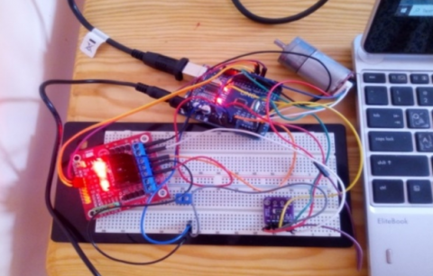
Figure 3. DC motor hardware setup
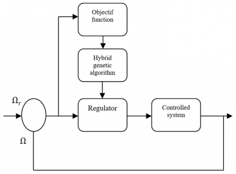
Using hybrid genetic algorithmic program as associate improvement tool to facilitate the manual effort of trial and error [21], the determination of the speed controller parameters, is obtained by the diminution of quadratic speed error of hybrid genetic algorithmic program as associate improvement tool to DC motor in steady state that enables the search of optimum answer of the subsequent objective function.
$\operatorname{Min}\left(f_{o b j}=\int_0^{t f}\left(\Omega-\Omega_{r e f}\right)^2 d t\right)$ (12)
Figure 4 shows the principle of this procedure scheme. Besides this optimization needs the determination of different operators of GAs such as coding, fitness, selection, mutation, crossover and mutation. In this study it has used: - Real coding of each individual composed by genes. We have choose the following parameters.
Figure 4. Basic structure of optimization speed controller gains by the hybrid genetic algorithms
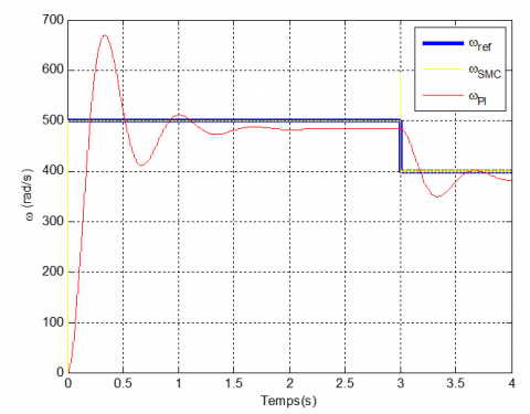
The result of numerical simulation using Matlab Software Figure 3 and the hardware implementation using the Arduino microcontroller were seen in Figure 5, we used a equation command (12). In this paper the reference speed is 500 rpm, for this speed, the current is 27,32 mA, and the electromagnetic torque 1.15 kg.cm.
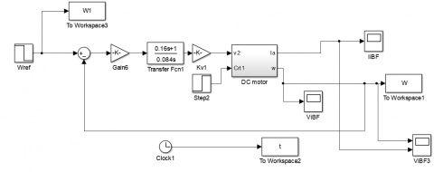
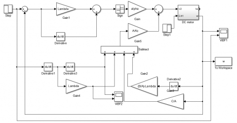
Figure 5. Simulation of SMC and PI of system
5.1 Numerical simulation
From the system response, it can be seen that the motor speed follows the given reference. The role of the integral action is to cancel the difference between the measurement and the set point (the static error is zero).
The effects of the PI corrector are:
- Decreased rise time.
- Elimination of static error.
- Increased stabilization time.
- Increased overshoot.
According to the satisfactory results obtained in Figure 6, it can be seen that the motor speed follows its reference, which shows that the use of sliding control of the system has better performance compared to the PI which is a faster stabilization time and the response time by sliding mode is better compared to the PI corrector. Table 2 gives comparison between SMC and PI.
Table 2. System response performance
|
Controller |
System response performance |
||
|
Settling time |
Overshoot % |
Static error |
|
|
SMC |
7.5.10-3 |
0 |
0 |
|
PI |
1.5 |
38 |
16 |
Figure 6. Numerical simulation of SMC and PI of system
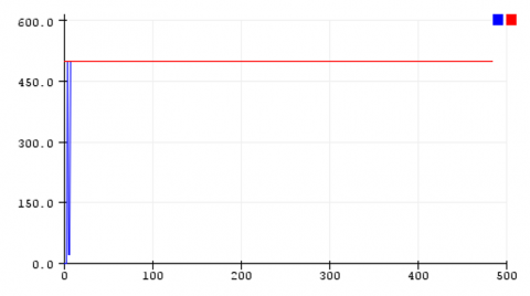
5.2 Arduino hardware implementation
The hardware implementation would be done using Arduino, JGA25 DC motor, L298 driver motor, encoder and INA219 current sensor. The configuration of the device is shown in Figure 3.
The result of PI is shown in Figure 7. The control signal SMC is shown in Figure 8. It can be seen that the system was able to reach the reference quickly in SMC compared with PI. The detailed system response is shown in Table 3.
Figure 7. The control signal PI controller
Figure 8. The control signal SMC
Table 3. System response performance
|
Controller |
System response performance |
||
|
Settling time |
Overshoot % |
Static error |
|
|
SMC |
47.10-3 |
0 |
0 |
|
PI |
1.04 |
0 |
0.23.10-3 |
The sliding mode control shows good performance in tracking and speed regulation (response speed without overshoot, without static error). The strong point of this regulation technique is the simplicity of implementation and the robustness even in the presence of internal and external disturbances with a very short response time. Finally, we can conclude that the essential characteristic of this technique is the capacity for robustness in the whole steady state. The simulation results show us that the responses with the SMC for speed control are more efficient. The proposed approach achieves:
·Good pursuit of reference speed;
·Starting without over shoot.
|
Ra |
Armature resistance Ω |
|
La |
The armature inductance H |
|
J |
Inertia Kg/m2 |
|
fr |
Coefficient of friction Nm s/rad |
|
Ke |
Cst Nm/A |
|
Kc |
Cst Nm/A |
|
Ω |
Speed |
|
U |
Voltage |
|
λ |
Positive constant |
|
S |
Sliding surface |
|
δ |
A small and positive parameter |
|
$\dot{e}$ |
The error derivative |
|
$\ddot{e}$ |
The error second derivative |
|
Ueq |
The equivalent command |
|
Un |
The convergence command |
[1] Sabir, M.M., Khan, J.A. (2014). Optimal design of PID controller for the speed control of DC motor by using metaheuristic techniques. Advances in Artificial Neural Systems. https://doi.org/10.1155/2014/126317
[2] Frayyeh, H.F., Mukhlif, M.A., Abbood, A.M., Keream, S.S. (2019). Speed control of direct current motor using mechanical characteristics. Journal of Southwest Jiaotong University, 54(4). https://doi.org/10.35741/issn.0258-2724.54.4.25
[3] Mane Devanand, B., KoliRohan, B., BhosaleSushilraje, S., JogdandVishakha, V. (2017). Arduino based speed control of DC motor by using LabVIEW. International Journal of Innovative Research in Science, Engineering and Technology (IJIRSET), 6(5). https://doi.org/10.15680/IJIRSET.2017.0605288
[4] Bhavithra, M., Gengagowri, B., Valarmathi, S., Josephine, J. (2016). Speed and direction control of DC motor by current and voltage controlled device by android application. IJIRSE International Journal of Advance Research in Science and Engineering, 7(2). https://doi.org/10.36713/epra2016
[5] Ahmad, M.A., Rai, P. (2014). Speed control of a DC motor using controllers. Automation, Control and Intelligent Systems, 2(6-1): 1-9. https://doi.org/10.11648/j.acis.s.2014020601.11
[6] Maghfiroh, H., Sujono, A., Apribowo, C.H.B. (2020). Basic tutorial on sliding mode control in speed control of DC-motor. Journal of Electrical, Electronic, Information, and Communication Technology, 2(1): 1-4. https://doi.org/10.20961/jeeict.2.1.41354
[7] Ambesange, S.V., Kamble, S.Y., More, D.S. (2013). Application of Sliding Mode Control for the speed control of DC motor drives. In 2013 IEEE International Conference on Control Applications (CCA), pp. 832-836. https://doi.org/10.1109/CCA.2013.6662853
[8] Maghfiroh, H., Wahyunggoro, O., Cahyadi, A.I., Praptodiyono, S. (2013). PID-hybrid tuning to improve control performance in speed control of DC motor base on PLC. In 2013 3rd International Conference on Instrumentation Control and Automation (ICA), pp. 233-238. https://doi.org/10.1109/ICA.2013.6734078
[9] Dursun, E.H., Durdu, A. (2016). Speed control of a DC motor with variable load using sliding mode control. International Journal of Computer and Electrical Engineering, 8(3): 219-226. https://doi.org/10.17706/ijcee.2016.8.3.219-226
[10] Heidari, Y., RanjbarNoee, A., Shayanfar, H.A., Salehi, S. (2010). Robust control of DC motor using fuzzy sliding mode control with fractional PID compensator. The Journal of Mathematics and Computer Science, 1(4): 238-246. https://doi.org/10.22436/JMCS.001.04.01
[11] Rakhtala, S.M., Roudbari, E.S. (2016). Application of PEM fuel cell for stand-alone based on a fuzzy PID control. Bulletin of Electrical Engineering and Informatics, 5(1): 45-61. https://doi.org/10.11591/eei.v5i1.521
[12] Ang, K.H., Chong, G., Li, Y. (2005). PID control system analysis, design, and technology. IEEE Transactions on Control Systems Technology, 13(4): 559-576. https://doi.org/10.1109/TCST.2005.847331
[13] Maghfiroh, H., Sujono, A., Apribowo, C.H.B. (2020). Basic tutorial on sliding mode control in speed control of DC-motor. Journal of Electrical, Electronic, Information, and Communication Technology, 2(1): 1-4. https://doi.org/10.20961/jeeict.2.1.41354
[14] Tir, Z., Malik, O., Hamida, M.A., Cherif, H., Bekakra, Y., Kadrine, A. (2017). Implementation of a fuzzy logic speed controller for a permanent magnet dc motor using a low-cost Arduino platform. In 2017 5th International Conference on Electrical Engineering-Boumerdes (ICEE-B), pp. 1-4. https://doi.org/10.1109/ICEE-B.2017.8192218
[15] Cárcamo, A.A.C., Reyes, M.G.M., Urbina, S.M.S. (2019). Low cost Pulse Oximeter using Arduino. In 2019 IEEE CHILEAN Conference on Electrical, Electronics Engineering, Information and Communication Technologies (CHILECON), pp. 1-6. https://doi.org/10.1109/CHILECON47746.2019.8988029
[16] Kumar, M.S., Chandra, T.R., Kumar, D.P., Manikandan, M.S. (2016). Monitoring moisture of soil using low cost homemade soil moisture sensor and Arduino UNO. In 2016 3rd International Conference on Advanced Computing and Communication Systems (ICACCS), pp. 1-4. https://doi.org/10.1109/ICACCS.2016.7586312
[17] Găşpăresc, G. (2016). PID control of a DC motor using Labview Interface for Embedded Platforms. In 2016 12th IEEE International Symposium on Electronics and Telecommunications (ISETC), pp. 145-148. https://doi.org/10.1109/ISETC.2016.7781078
[18] Alfano, A.G., Maghfiroh, H., Iftadi, I., Hermanu, C., Adriyanto, F. (2019). Modelling and simulation of dc motor speed control using fuzzy-pid algorithm. Journal of Electrical, Electronic, Information, and Communication Technology, 1(1): 13-18. https://doi.org/10.20961/jeeict.v1i1.34260
[19] Syllignakis, J., Panagiotakopoulos, P., Karapidakis, E. (2016). Automatic speed controller of a DC motor using arduino, for laboratory applications. Engineering and Industry Series. https://doi.org/10.22618/TP.EI.20163.389029
[20] Amimeur, H., Aouzellag, D., Abdessemed, R., Ghedamsi, K. (2012). Sliding mode control of a dual-stator induction generator for wind energy conversion systems. International Journal of Electrical Power & Energy Systems, 42(1): 60-70. https://doi.org/10.1016/j.ijepes.2012.03.024
[21] Malhotra, R., Singh, N., Singh, Y. (2011). Genetic algorithms: Concepts, design for optimization of process controllers. Computer and Information Science, 4(2): 39. https://doi.org/10.5539/cis.v4n2p39