Hussein M. Ali | Emad Toma Karash* | Mohammad T. Elias
© 2022 IIETA. This article is published by IIETA and is licensed under the CC BY 4.0 license (http://creativecommons.org/licenses/by/4.0/).
OPEN ACCESS
The ultrasonic vibration reaming (UVR) cutting process is one types of non-Conventional machining process which was tested in this study to show whether its effective method or not. In this process, the tool is imposed on ultrasonic wave to produce vibration along the host cutting movement direction, formed the separation type of vibration process affected by waveform of pulse force. The effect of cutting speed, feed and ream allowance upon the surface roughness and circular degree in reaming a hole of C45 steel were studied in this paper. The results show that the surface quality and machining accuracy of the hole have been improved by using the technology of the present study. At the same time, the cutting force and cutting temperature has reduced correspondingly. In conclusion, it was noticed that the (UVR) is effective cutting techniques for high-precision "thin-hole" machining of the material under this study with respect to the conventional reaming process.
ultrasonic vibration, reaming, surface roughness, circular degree
Over the recent years, the development of science and technology is rapidly increased, especially in the aerospace, electronics, instruments and meters, precision machinery, automatic control and medical equipment, etc. To collect many parts in several industrial applications, it becomes necessary to product a bolt holes during machining of various materials. The demand for the machining of a precision holes in a structure was increased [1, 2]. Reaming is a machining process in which a light cut to improve the accuracy of around hole and enlarges an existing hole to the diameter of the tool that led to obtain accuracy holes, and this target can be reached after rotating an accuracy cutting tool called reamer into a hole sized slightly. There are several types of reamers and they may be prepared for use as a hand tool, or as in a drill press, etc. However, when ordinary reaming process is applied, the temperature at the cutting area, cutting torque and tool life are greatly affected upon the cut quality. Therefore, it becomes necessary to looking for an alternative reaming process to improve the cut quality and precision of hole size. Ultrasonic vibration reaming process, was adopted for this purpose. In this process, the piezoelectric transducer is used to generate a high frequency in the order of 16-21 kHz and low amplitude vibration in the order of 2-15 μm. These vibrations are superimposed in the drill with the help of a sonotrode in the longitudinal mode. This technology was put forward in 1950 by Japanese scholar Kumabe Junichiro. Then, the researchers of United States, Soviet Union, Britain and Germany did a lot of work on vibration cutting [3]. In the literatures, a little work was found on using ultrasonic vibration in reaming process. Zhang et al. [4] summarized the procedures of the (UVR)"thin-hole" in hardened steel. They concluded that the (UVR) using reamer is of high excellent cutting technique for high-accuracy "thin-hole" machining of hardened material. Celaya et al. [5] investigated the effect of tool vibration upon the quality of surface for mild steels using the ultrasonic vibration assisted turning of mild steel. The researchers concluded that the ultrasonic vibration technology can improve the surface quality depending on the cutting conditions (cutting speed, feed and depth of cut). The effects of using ultrasonic vibration-facilitated milling technology on important sides of tool wear, cutting forces and surface integrity of Alloy 718, which is common use in high temp. applications has been investigated by Suárez et al. [6]. Their outcome be seen alterations in the sub- superficial part of the material which could affect the fatigue resistance of the material. Tool wear manner was observed also to be very comparable for both milling technologies. The principal analysis on (RUAD) of (CFRP) was presented by Li et al. [7] to explain the removal process of rod and chip. After that, the experiment analysis on (RUAD) of (CFRP) was execution it to observe the removal effects of rod & chip. The experimental outcome point to compared with the public drilling of core drill, when the vibration amplitude arrived 5.00 & 7.50 µm in (RUAD), the ability of cutting of core drill tool was quite reinforced, very good removal effects of rod & chip were obtained, which obviously reduced the, rod jamming, chip adhesion, cutting temp., thrust force, rod fragmentation, and surface roughness, improved rod diam. and the dimensional accuracy of machined hole, prolonged the tool life, in addition to acquired superior surface integrity of machined hole and flat fibers fracture surfaces, also the experimental outcomes proved the accuracy of the principal analysis. Kumar and Rameshkumar [8] used an ultrasonic assisted tool (UAT) made of Aluminium-7075-T6/HSS M2 as a first designed for a theoretical amplification ratio of 4. Then modal and harmonic analyses were carried out for six different dimensions of the UAT i.e., D10d5, D14d7, D16d8, D20d10, D24d12 and D30d15. Natural frequency and vibration amplitude at the tool end are determined. They concluded that the D16d8 UAT is the best suited dimension for the design criteria considered providing the required amplification of 4. Geng et al. [9] studied the feasibility "ultrasonic elliptical vibration assisted"(UEVA) reaming of carbon fiber reinforced plastics-titanium alloy stacks. In their study, they analyzed the compared between conventional reaming and the tool performance and hole quality in (UEVA). They found that the quality of holes was obviously enhance in (UEVR). This is proved by monitoring surface finish, cutting force, and hole geometric precision. Li et al. [10] introduced an 8-facet drill tool and combined the advantages of (RUAD) to carry out a study on the drilling of (Ti6Al4V) under no cooling condition. Their experimental outcome indicated that the thrust force, torque, cutting temp. near the drilled hole exit, expansion increment of hole diam., surface roughness of drilled hole, and burr height of drilled hole exit decreased by 16.79 to 20.2%, 31.5 to 33.6%, 18.54 to 21.68%, 24.87 to 25.36%, 46.75 to 57.63%, and 82.27 to 89.18%, respectively; compared with the common drilling of (Ti6Al4V), Furthermore, the experimental outcome also proved that the drilling technology of (RUAD) of (Ti6Al4V) using the 8-facet drill was practical and the cutting effects were excellent." There are many researches that dealt with this topic, and the uses of different variables, and reached results of scientific interest on this topic [11-25]. Sharma et al. [26] studied the influence of cutting force and drilling temperature on glass hole surface integrity during rotary ultrasonic drilling. They investigated experimentally the surface roughness while drilling a hole in glass specimen using rotary ultrasonic machining (RUD). The authors were concluded that the best drilling condition to get the least value of average surface roughness (167.702 nm) is the usage of coolant with 5000 rpm of spindle speed.
In the present work, the ultrasonic vibration technique has been used to assess the effects of cutting speed, feed and ream allowance depth of reaming process upon the surface roughness and circular degree in hole making of C45 steel.
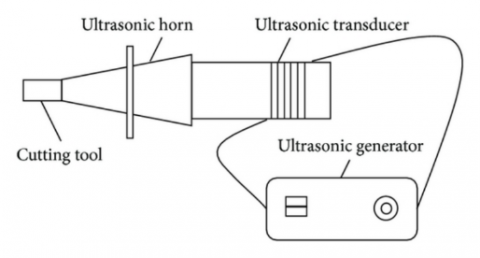
As presented in Figure 1. The cutting tool is imposing on the ultrasonic wave and vibrate at a certain vibration amplitude and frequency and form a separated type pulse force of vibration along the host cutting movement direction [27]. The chip formed by this type of cutting technology is regular in thickness, no difference in color and the cutting temp. is not different as the room temp. The tool life is highly improved with no clear abrasion in the cutting operation. The cutting operation is very stable, changed the extrusion of cutting-edge act on ablation zone of work piece into almost pure cutting process, cutting deformation is minimal shrinkage coefficient is approximation equal to one, cutting force is only 1/10-1/3 of the normal cutting; Graph of cutting zone temperature is pulse shape, so average cutting temperature is very low, producing little cutting heat, cutting process at room temperature, the tools rarely wear. Machine surface is composed of numerous tiny flat or curved forming a beautiful pattern [28-30].
Figure 1. Experimental setup
The control parameters were selected depending on the feed rate & spindle speed available on the machine. The control parameters during the reaming process were performed under the conditions of cutting speed (m/min), feed rate (mm/min) separately. Each test group for reaming included three test samples. The averages of three measurement values were obtained to get the mean value.
3.1 Material
For the empirical tests, a round bars of medium carbon steel (C45) produced by Ningbo Preah Vihear steel Industry Co., Ltd. / China was used. Medium carbon steel (C45) is used when high strength and hardness is required such as in: building, automobile, shipbuilding, petrochemical, machinery, medicine, electric power, energy, space, building and decoration, etc. The chemical composition and mechanical properties for C45 steel can be shown in Table 1 and 2 [15].
Table 1. Chemical composition of C45 steel by weight%
|
Chemical elements |
C % |
Si % |
Mn % |
Su % |
Ph % |
Fe % |
|
Standard value, C40 Steel, [31] |
0.37 - 0.44 |
0.4 max. |
0.5 – 0.8 |
0.45 max. |
0.045 max. |
Rem. |
|
Actual value |
0.41 |
0.13 |
0.73 |
0.42 |
0.039 |
98.27 |
Table 2. Mechanical properties of C45 steel
|
Property |
Tensile strength, MPa |
Yield Strength, MPa |
Impacting Energy, J |
Poisson’s ratio |
Hardness, HBS |
Elongation % |
|
Standard value, C40 Steel, [30] |
590 - 880 |
350 - 550 |
40 - 60 |
0.27 - 0.3 |
180 - 230 |
8 - 25 |
|
Actual, value |
655 |
365 |
49 |
0.28 |
218 |
16 |
3.2 Experimental procedure for reaming
All the reaming tests were achieved by using the ultrasonic vibration reaming system (UVR). The UVR system consists of: ultrasonic generator with output power of 0-500w, ultrasonic transducer of (25 KHz, 500 watts made by Shenzhen yike ultrasonic company, China), horn which acts as tool holder in addition to an amplifier (The horn is of a length 100mm, made of aluminum material with natural frequency of 20, 527 Hz. and finally, the UVR system include the reamer tool. Schematic diagram for the ultrasonic vibration system used in the experiments can be shown in Figure 2. In ultrasonic transducer, piezoelectric material is used same as quartz. The ultrasonic vibration system giving ultrasonic sound in the form of vibration to the reamer tool at amplitude of 0.01 mm and frequency of 20 KHZ.
Figure 2. Structure sketch of ultrasonic vibration system
A reamer with 10.0 mm diam. was used through the experiments. The specification of reamer is illustrated in table The reamer diam. was calculated before and after every experiment employing a digital micrometer and the mean value of ten magnitudes on Table 3 pair of flutes was estimated. This value was invariable within a range of 1μm appearing that no reduction in reamer diameter due to wear during the whole investigation. The vibration direction was along the diameter of the bar.
A set of three specimens were carried out to measure the average value of the response variables (surface roughness and circular degree). The dimensions of the specimen material of the material were (Φ16mm× 60mm). The required bore diam. of the reamed hole is 10mm.
Table 3. Reamer specification
|
Material |
HSS-E COBALT |
|
|
Shank |
DIN 212-8 NFE 66014 |
|
|
No. of flutes |
6 |
|
|
Dimensions [mm] |
||
|
D |
10.0 10.1 |
|
|
L |
133±1 |
|
|
l1 |
38±1 |
|
|
l2 |
99 |
|
|
D2 |
10.0 |
|
|
Tolerance |
±0.003 |
|
The outcomes are presented in Table 4. The following is description of the response variables (surface roughness, dimensional accuracy):
Table 4. Experimental results
|
No. |
Cutting Speed (m/min) |
Roughness ($\mu m$) |
Feed Rate (mm/r) |
Roughness ($\mu m$) |
Depth of Reaming (mm) |
Roughness ($\mu m$) |
|
1 |
0 |
0 |
0 |
0 |
0 |
0 |
|
2 |
5 |
0.17 |
0.05 |
0.14 |
0.1 |
0.19 |
|
3 |
10 |
0.18 |
0.1 |
0.16 |
0.2 |
0.18 |
|
4 |
15 |
0.18 |
0.15 |
0.165 |
0.3 |
0.15 |
|
5 |
20 |
0.18 |
0.2 |
0.19 |
0.4 |
0.27 |
|
No |
Cutting Speed (m/min) |
Circular degree (mm) |
Feed Rate (mm/r) |
Circular degree (mm) |
Depth of Reaming (mm) |
Circular degree (mm) |
|
1 |
0 |
0 |
0 |
0 |
0 |
0 |
|
2 |
5 |
0.003 |
0.05 |
0.003 |
0.05 |
0.015 |
|
3 |
10 |
0.0028 |
0.1 |
0.0039 |
0.1 |
0.003 |
|
4 |
15 |
0.0029 |
0.15 |
0.0042 |
0.15 |
0.0035 |
|
5 |
20 |
0.0041 |
0.2 |
0.005 |
0.2 |
0.0035 |
Figures 3, 4 & 5 show the effect of cutting speed, feed rate & depth of reaming separately upon the surface roughness & the circular degree respectively. The following are description of the effect for each input parameter upon the response variables (surface roughness & circular degree of the cutting surface.
5.1 The effect of cutting speed on the surface roughness & circular degree
Figure 3 illustrate the effect of cutting speed (ν) upon the surface roughness (Ra) & circular degree under the test conditions. It was shown from the figure that, when the speed of cutting (ν) is less than vibrating velocity (νt), the surface roughness is almost nothing to do with speed of cutting. While, when speed of cutting is higher than vibrating velocity, surface roughness has no difference as common reaming. So, the significant effect of ultrasonic vibration reaming will be obtained only when the cutting speed is lower than vibrating velocity (νt=aω=2πaf) and ν≤1/3 νt when dry type ultrasonic vibration reaming.
Figure 3. The influence of cutting speed upon: a- the surface roughness & b- Circular degree, where, ap=0.1 mm; s=0.1 mm/r
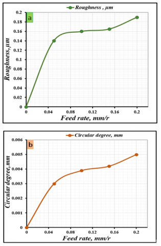
5.2 The relationship between surface roughness and the feed rate
The relationship between the feed rate (s) & the surface roughness (Ra) under the test conditions is shown in Figure 4. It was shown from the figure that when the feed rate increases, the surface roughness increases slightly. This is because the reamer vibration along the main cutting direction in the cutting process, rather than along the feed motion synthesis direction vibration, feeding the greater the impact, the more prominent. Feed movement of the cutting is not fully pulse.
5.3 The relationship between surface roughness & the depth of the reaming
The relationship between the reaming depth and the surface roughness is illustrated in Figure 5. It can be shown from the figure that the depth of cut has slight effect upon the surface roughness of when the reaming depth less than 0.10mm While, when reaming depth is more than 0.10mm, the values of roughness increase clearly with the increasing the depth of the reaming. This is because of the increases in the cutting force with the increase in cutting depth, ultrasonic power cannot meet the requirement. Simultaneously, the increase in the radial interference is larger when the tool is disengaged. The max. interference value along the radial is equivalent to the reaming depth and as a result of this, the (UVR) is affected by the flank interference with the cutting surface when the reaming depth is large. Therefore; (UVR) should be used for small reaming depth.
Figure 4. The influence of feed rate upon: a- the surface roughness & b- Circular degree, where, ap=0.1 mm; s=0.1 mm/r
Figure 5. The influence of depth of reaming upon: a- the surface roughness & b- Circular degree, where, ap=0.1 mm; s=0.1 mm/r
5.4 Circular degree
The circular degree of the processing part is one of the important indexes of machining accuracy. The outcome displays that the circular degree of the (UVR) is relatively higher than that obtained by the conventional method. Figures 6-8 show the influence of the cutting parameters upon the circular degree.
It was shown from the figures that with the increase of the cutting speed and feed, the circular degree of the work piece increased slightly, while with the increase of depth of reaming, the circular degree of the work piece gradually reduces and it tends to be stable when the ream allowance is 0.1mm.
Figure 6. The influence of cutting speed upon the circular degree, where, ap=0.1 mm (unilateral); s=0.1 mm/r
Figure 7. The influence of cutting feed on the circular degree, where, ap=0.1 mm (unilateral); v=9.1 m/min
Figure 8. The influence of depth of reaming on the circular degree, where, v=9.1 m/min; s=0.1 mm/r
The surface quality and circularity degree of the hole have been improved dramatically by ultrasonic vibration reaming processing technology due its vibro-impact. It was shown from the Figures 6, 7 & 8 that with the increase of the cutting speed and feed, the circular degree of the work piece increased slightly, while with the increase of depth of reaming, the circular degree of the work piece gradually reduces and it tends to be stable when the ream allowance is 0. 1mmThe following conclusions can be drawn based on the results of the experimental study on reaming of carbon steel by ultrasonic vibration reaming process:
(1) The surface roughness was decreased clearly and this is because of the removal of plastic deformation in machining operation which reduce the effect of micro elastic vibration & physical factors of the experimental system. Simultaneously, cutting force and cutting temperature has reduced correspondingly.
(2) The comparison made with the results obtained for the circular degree by using the conventional method with that obtained by the present study of the (UVR) is relatively higher than that obtained by the conventional method due to the axial vibration, which will contribute to reducing the cutting forces and improving the heat dissipation. Meanwhile, a friction effect was generated by the peripheral cutting edge which can improve the micro-scale surface roughness.
(3) It was shown from Figures 5 & 8 that (UVR) should be used for small reaming depth because it gives low roughness and good circular degree.
The authors of the present work wish to thank the staff of College of Electrical and Mechanical Engineering / Nanjing University of Astronautic and Aeronautic in performing the experimental work in their labs.
|
Ra |
Arithmetic surface roughness |
|
ν |
Cutting speed |
|
νt |
Vibrating velocity |
|
a |
Amplitude of vibration |
|
f |
Frequency of vibration |
|
s |
Feed rate |
|
ap |
Depth of the ream |
[1] Isobe, H., Uehara, Y., Hara, K. (2012). Effect of ultrasonic vibration drilling on cutting stress distribution. Key Engineering Materials, 523-524: 191-196. https://doi.org/10.4028/www.scientific.net/KEM.523-524.191
[2] Nath, C., Rahman, M. (2008). Effect of machining parameters in ultrasonic vibration cutting. International Journal of Machine Tools and Manufacture, 48(9): 965-974. https://doi.org/10.1016/j.ijmachtools.2008.01.013
[3] Zhang, J., Li, X., Shen, K. (2004). Experimental study of ultrasonic vibration dry-reaming. Electro Machining & Mould, 4(1): 1-6.
[4] Zhang, J.Z., Zhang, N.C., Zhang, Y. (2013). Study on reaming high-precision thin hole in hardened steel by ultrasonic vibration reamer. Advanced Materials Research, 503: 396-399. https://doi.org/10.4028/www.scientific.net/AMR.503-504.396
[5] Celaya, A., Lopez de Lacalle, L.N., Campa, F.J., Lamikiz, A. (2010). Ultrasonic assisted turning of mild steels. International Journal of Materials & Product Technology, 37(1-2): 60-70. https://doi.org/10.1504/IJMPT.2010.029459
[6] Suárez, A., Veiga, F., de Lacalle, L.N.L., Polvorosa, R., Lutze, S., Wretland, A. (2016). Effects of ultrasonics-assisted face milling on surface integrity and fatigue life of Ni-Alloy 718. Journal of Materials Engineering and Performance, 25(11): 5076-5086. https://doi.org/10.1007/s11665-016-2343-6
[7] Li, Z., Zhang, D., Qin, W., Geng, D. (2016). Removal analyses of chip and rod in rotary ultrasonic-assisted drilling of carbon fiber-reinforced plastics using core drill. Journal of Reinforced Plastics and Composites, 35(15): 1173-1190. https://doi.org/10.1177/0731684416644510
[8] Kumar, N.S., Rameshkumar, A. (2017). Exploration of UAT for ultrasonic assisted drilling of CFRPs. In: International Conference on Adaptive Technologies for Sustainable Growth (ICATS); March 2017; Paavai Engineering College, Namakkal, Tamil Nadu, India.
[9] Geng, D., Zhang, D., Li, Z., Liu, D. (2017). Feasibility study of ultrasonic elliptical vibration-assisted reaming of carbon fiber reinforced plastics/titanium alloy stacks. Ultrasonics, 75: 80-90. https://doi.org/10.1016/j.ultras.2016.11011
[10] Li, Z., Zhang, D., Jiang, X., Qin, W., Geng, D. (2017). Study on rotary ultrasonic-assisted drilling of titanium alloys (Ti6Al4V) using 8-facet drill under no cooling condition. International Journal of Advanced Manufacturing Technology, 90(9): 3249-3264. https://doi.org/10.1007/s00170-016-9593-1
[11] Saleem, M., Toubal, L., Zitoune, R., Bougherara, H. (2013). Investigating the effect of machining processes on the mechanical behavior of composite plates with circular holes. Composites Part A: Applied Science and Manufacturing, 55: 169-177. https://doi.org/10.1016/j.compositesa.2013.09.002
[12] Amini, S., Kazemiyoun, M. (2014). Effect of ultrasonic vibrations on chip–tool contact zone in turning of AISI304. Materials and Manufacturing Processes, 29(5): 627-633.https://doi.org/10.1080/10426914.2014.901521
[13] Sultan, J.N., Karash, E.T., Abdulrazzaq, T.K., Kassim, M.T.E. (2022). The effect of multi-walled carbon nanotubes additives on the tribological properties of austempered AISI 4340 steel. Journal Européen des Systèmes Automatisés, 55(3): 387-396. https://doi.org/10.18280/jesa.550311
[14] Zhang, X., Liu, K., Kumar, A.S., Rahman, M. (2014). A study of the diamond tool wear suppression mechanism in vibration-assisted machining of steel. Journal of Materials Processing Technology, 214(2): 496-506. https://doi.org/10.1016/j.jmatprotec.2013.10.002
[15] Toropov, A., Ko, S.L. (2003). Prediction of tool-chip contact length using a new slip-line solution for orthogonal cutting. International Journal of Machine Tools and Manufacture, 43(12): 1209-1215. https://doi.org/10.1016/S0890-6955(03)00155-X
[16] Toropov, A., Ko, S.L. (2007). Prediction of shear angle for continuous orthogonal cutting using thermo-mechanical constants of work material and cutting conditions. Journal of Materials Processing Technology, 182(1-3): 167-173. https://doi.org/10.1016/j.jmatprotec.2006.07.027
[17] Bahi, S., Nouari, M., Moufki, A., El Mansori, M., Molinari, A. (2012). Hybrid modelling of sliding–sticking zones at the tool–chip interface under dry machining and tool wear analysis. Wear, 286: 45-54. https://doi.org/10.1016/j.wear.2011.05.001
[18] Pogrebnjak, A.D., Muhammed, A.A., Karash, E.T., Jamil, N.Y., Partyka, J. (2013). Effects of Al dopant on structural and optical properties of ZnO thin films prepared by sol-gel. Partyka. Przeglad Elektrotechniczny, 89(3): 315-317.
[19] Ali, H.M., Iqbal, A., Liang, L. (2013). A comparative study on the use of drilling and milling processes in hole making of GFRP composite. Sadhana, 38(4): 743-760. https://doi.org/10.1007/s12046-013-0186-5
[20] Ali, H.M., Iqbal, A., Hashemipour, M. (2014). Dimensional accuracy and strength comparison in hole making of GFRP composite using CO2 laser and abrasive water jet technologies, Niscair-Csir, India. Indian Journal of Engineering and Material Science, 41: 189-199.
[21] Cakir, F.H., Gurgen, S., Sofuoglu, M.A., Celik, O.N., Kushan, M.C. (2015). Finite element modeling of ultrasonic assisted turning of Ti6Al4V alloy. Procedia-Social and Behavioral Sciences, 195: 2839-2848. https://doi.org/10.1016/j.sbspro.2015.06.404
[22] Chou, C.L. (1994). Wave Effects of Ultrasonic Vibration on Machining. University Park, PA: Pennsylvania State University.
[23] Özel, T., Zeren, E. (2004). Determination of work material flow stress and friction for FEA of machining using orthogonal cutting tests. Journal of Materials Processing Technology, 153: 1019-1025. https://doi.org/10.1016/j.jmatprotec.2004.04.162
[24] Brinksmeier, E., Janssen, R. (2002). Drilling of multi-layer composite materials consisting of carbon fiber reinforced plastics (CFRP), titanium and aluminum alloys. CIRP Annals, 51(1): 87-90. https://doi.org/10.1016/S0007-8506(07)61472-3
[25] Xu, J., Mkaddem, A., El Mansori, M. (2016). Recent advances in drilling hybrid FRP/Ti composite: A state-of-the-art review. Composite Structures, 135: 316-338. https://doi.org/10.1016/j.compstruct.2015.09.028
[26] Sharma, A., Babbar, A., Jain, V., Gupta, D. (2021). Influence of cutting force and drilling temperature on glass hole surface integrity during rotary ultrasonic drilling. Advances in Production and Industrial Engineering, 369-378. https://doi.org/10.1007/978-981-15-5519-0_28
[27] Sultan, J.N., Abbas, M.K., Abd-al Kareem Ibrahim, M., Karash, E.T., Ali, A.M., Ibrhim, H.A. (2021). Corrosion behavior of thermal seamless carbon steel boiler pipes. Annales de Chimie-Science des Matériaux, 45(5): 399-405. https://doi.org/10.18280/acsm.450506
[28] Li, X., Zhang, D. (2006). Ultrasonic elliptical vibration transducer driven by single actuator and its application in precision cutting. Journal of Materials Processing Technology, 180(1-3): 91-95. https://doi.org/10.1016/j.jmatprotec.2006.05.007
[29] Ma, C., Shamoto, E., Moriwaki, T., Wang, L. (2004). Study of machining accuracy in ultrasonic elliptical vibration cutting. International Journal of Machine Tools and Manufacture, 44(12-13): 1305-1310. https://doi.org/10.1016/j.ijmachtools.2004.04.014
[30] Shimada, S., Tanaka, H., Higuchi, M., Yamaguchi, T., Honda, S., Obata, K. (2004). Thermo-chemical wear mechanism of diamond tool in machining of ferrous metals. CIRP Annals, 53(1): 57-60. https://doi.org/10.1016/S0007-8506(07)60644-1
[31] Mahmood, S.N. (2014). Study the effect of surface and internal heat treatment on mechanical properties of C40 steel alloy. Engineering and Technology Journal, 32(4): 922-931.