Karima Benamrane* | Thameur Abdelkrim | Boualam Benlahbib | Noureddine Bouarroudj | Abdelkader Lakhdari | Abdelhalim Borni | Ahmed Bahri
© 2022 IIETA. This article is published by IIETA and is licensed under the CC BY 4.0 license (http://creativecommons.org/licenses/by/4.0/).
OPEN ACCESS
This paper deals with the modeling and control of a new two-stage photovoltaic conversion cascade composed of a Three-Level Boost (3LB) converter and a three-phase NPC five-level inverter (5LI). The main objective is to ensure the continuity of energy transfer from a renewable continuous source to the electrical grid while regulating the voltages of the DC bus capacitors with a new proposed configuration. The 3LB is controlled in MPPT based on fuzzy logic. A PI regulator is introduced into the 3LB regulation loop in order to maintain the equality of the two output voltages. The overall voltage of the DC bus being regulated by the control of the multilevel inverter interconnected to the grid, using synchronous reference frame control. Therefore, in our case there is the problem of voltages imbalance caused by the 5LI. We propose in this work to introduce two Clamping Bridges (CBs) each one is composed by a transistor in series with a resistor. These CBs are introduced in parallel with two capacitors of the DC bus. This solution avoids us to use the control algorithm by redundant configurations in the regulation loop of the 5LI. The results obtained show the effectiveness of the proposed control in stabilizing and maintaining the four DC bus voltages at equal values. With four balanced capacitor voltages, we get symmetrical inverter output voltage waveforms, which directly affects the quality of the current injected to the grid.
Three-Level Boost, five-level inverter, clamping bridges, SVPWM, DC bus control
To cope with the decrease in fossil resources and climate change, renewable energies are a particularly suitable response to the energy needs of the world. They therefore play an important role in the fight against climate change and therefore in the protection of human health. Migration to this type of energy allows long-term control of energy prices since it concerns energies produced from inexhaustible and free resources. Today, photovoltaic (PV) systems, wind generators and hydroelectric systems are the most widely used in the production of clean electrical energy. Currently, investment in the development and integration of these clean sources is becoming essential in order to meet the energy needs of countries.
In the early 1960s, multilevel converters made their appearance. These converters have several advantages: On the one hand, they allow distribution of the voltage stress on the power switches, which offers much higher performance than that of conventional structures. On the other hand, the waveform of the output voltage is of better spectral quality compared to that of a two-level voltage inverter. Indeed, the fact of increasing the number of switching cells per leg makes it possible to reduce the level of harmonic distortion of the output voltages. Today, these converters are increasingly used in production systems from renewable energies.
The history of multilevel converters began in the 1960s. The first structure described is an H-bridge series connection. Then, in the late 1970s, the Neutral Point Clamped (NPC) converter appeared [1]. This topology is considered the first multilevel converter intended for medium power applications. Since then, many studies have been proposed to study its properties and the possible evolutions of this structure.
Nowadays, new configurations of multilevel converter (DC/DC-DC/AC) topologies have appeared such as the five-level IT-type NPC inverter [2] or the single-input dual-output three-level DC-DC converter [3].
A multilevel NPC inverter uses intermediate capacitors which define the different voltage levels at its output. The major problem for the control of this type of converter is the balancing of the voltages of its capacitors in order to ensure the safety of the semiconductors. Indeed, the floating voltages evolve according to the command and the direction of circulation of the load current.
Several solutions are proposed by researchers for balancing capacitor voltages such as the use of balancing bridge [4-7] or redundant vectors [8-10].
Multilevel inverter structures are applied in single-stage or two-stage photovoltaic conversion cascades [11-17]. In this work, we are interested in the second configuration.
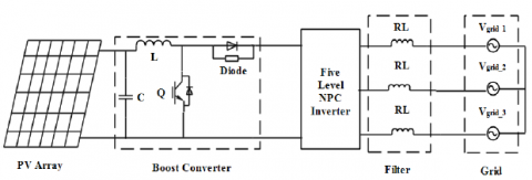
Belabbas et al. [7] in their work used a single DC/DC boost converter to fed the four capacitors of the 5LI (Figure 1). In this case, the authors use four balancing bridges to regulate the voltage values of the DC bus capacitors.
Figure 1. PV generator- DC/DC Boost converter - 5LI
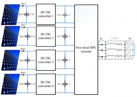
Sarthi et al. [18], Laib et al. [19] use four DC/DC Boost converters, each powered by its own photovoltaic generator (Figure 2). The redundant vectors of the vector diagram are applied for balancing the input voltages of 5LI.
Figure 2. Four PV generator- Four DC/DC Boost converters- 5LI
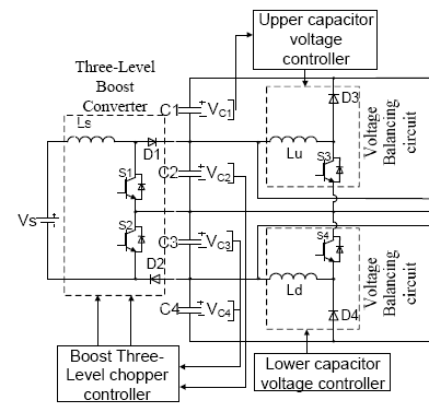
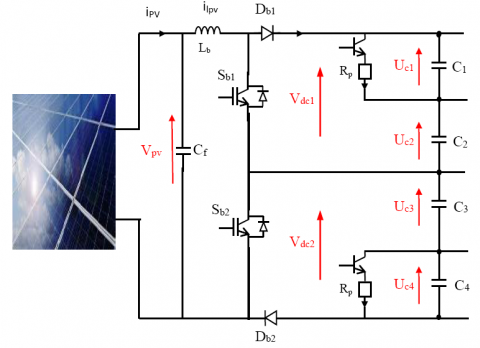
Abdullah et al. [20] in their work used a three-level boost connected with only two 5LI capacitors (Figure 3). In this case, the authors use two circuits composed of an inductance, a transistor and a diode to control the voltage of the upper and lower capacitors.
Figure 3. PV generator- Three-level boost converter - 5LI
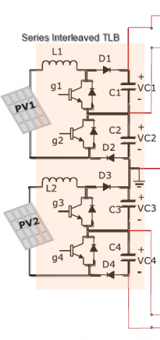
de Britto Florencio et al. [21] uses series interleaved three-level boost to fed the four capacitors of the 5LI (Figure 4). In this case, the two DC/DC converters regulate the capacitor voltages.
Figure 4. PV generators- series interleaved three-level boost converters - 5LI
Figure 5 presents the proposed configuration. Rosmadi et al. in their cascade introduced their 3LB to feed the two capacitors C2 and C3 [20]. Therefore, the voltages across them are constant. The voltages of the other capacitors C1 and C4 are regulated using an external circuit. In the configuration that we propose, the 3LB is introduced to regulate the sum of the voltages of the capacitors C1 and C2 as well as the sum of the voltages of the capacitors C3 and C4. Therefore, in our case there is the problem of voltages imbalance caused by the 5LI. We use in our case to solve this problem, two clamping bridges, each composed of a transistor and a resistor.
Figure 5. Proposed DC bus configuration
The three-level boost uses two switches and two diodes but only one inductor (Figure 6). The advantage of this structure is initially to halve the voltage constraints of the switches. The two switches are controlled with the same duty cycle but their controls are shifted from each other by half a period [22]. The averaged model of 3LB is:
$\left\{\begin{array}{l}L \frac{d i}{d t}=V_e-\left(1-\alpha_1\right) V_{d c 1}-\left(1-\alpha_2\right) V_{d c 2} \\ V_{d c 1}+V_{d c 2}=V_s\end{array}\right.$ (1)
Figure 6. Three-level boost
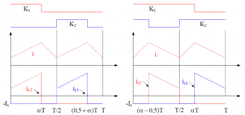
For the duty cycle α=α1 less than 0.5 and greater than 0.5, we have the waveforms of the current in the inductance of Figure 7.
Figure 7. Current waveform (α<0.5 left, α>0.5 right)
In the case where α<0.5, we have:
$\left(V_e-\frac{V_s}{2}\right) \alpha=-\left(V_e-V_s\right)(0,5-\alpha)$ (2)
Similarly, in the case where α>0.5, we have:
$V_e(\alpha-0,5)=-\left(V_e-\frac{V_s}{2}\right)(1-\alpha)$ (3)
We deduce from the two previous relations, the voltage gains of the converter:
$\frac{V_s}{V_e}=-\frac{1}{1-\alpha}$ (4)
The current ripple and the output voltage ripple are written:
$\left\{\begin{array}{l}\Delta i=\frac{V_e}{2 L f} \frac{\alpha(1-2 \alpha)}{1-\alpha} \\ \Delta V_s=\frac{2 I_s(0,5-\alpha)}{C f}=\frac{V_e(1-2 \alpha)}{(1-\alpha) R C f}\end{array} \quad\right.$ for $\alpha<0.5$ (5)
$\left\{\begin{array}{l}\Delta i=\frac{V_e}{2 L f}(2 \alpha-1) \\ \Delta V_s=\frac{2 I_s(\alpha-0,5)}{C f}=\frac{V_e(2 \alpha-1)}{(1-\alpha) R C f}\end{array} \quad\right.$ for $\alpha>0.5$ (6)
where, C=C1=C2.
The voltages at switches terminals and the diodes have the value:
$V_{k, \max }=\left|V_{d, \max }\right|=V_{c, \max }=\frac{V_e}{1-\alpha}+\frac{\Delta V_c}{2}$ (7)
with
$\Delta V_c=\frac{V_e}{R C f}$ for $\alpha<0.5$ (8)
and
$\Delta V_c=\frac{\alpha V_e}{(1-\alpha) R C f}$ for $\alpha>0.5$ (9)
Similarly, the maximum currents crossing the switches and the diodes are:
$i_{k, \max }=i_{d, \max }=i_{\max }=I+\frac{\Delta i}{2}$ (10)
There are several methods for finding the maximum power point (MPP) of a field of photovoltaic modules, which the efficiency and speed vary. Among these methods, the control of the MPPT based on fuzzy logic. Fuzzy logic controllers have been widely used in industrial processes in recent years due to their heuristic nature coupled with simplicity, efficiency and consideration of its multi-rule variable for parameter variation linear and nonlinear system.
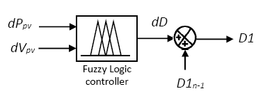
We apply in our work to the input of our regulator the variations of the power and voltage of the photovoltaic generator. We obtain at the output the variation of the duty cycle to which we add the duty cycle to obtain the control order D1 of the first transistor of the 3LB (Figure 8).
Figure 8. Fuzzy logic controller
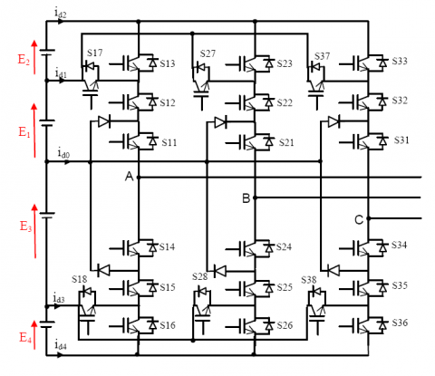
The five-level three-phase inverter used consists of three legs and four DC voltage sources. Each leg has eight switches and two middle diodes (Figure 9) [23].
Figure 9. Circuit diagram of 5LI
The following Table 1 summarizes the states of the inverter switches, which make it possible to obtain the five output voltages.
Table 1. States of the inverter switches
|
Switching States |
Output Voltage |
|||||||
|
Si1 |
Si2 |
Si3 |
Si4 |
Si5 |
Si6 |
Si7 |
Si8 |
|
|
ON |
ON |
ON |
OFF |
OFF |
OFF |
OFF |
OFF |
P2=E1+E2 |
|
ON |
ON |
OFF |
OFF |
OFF |
ON |
ON |
OFF |
P1=E1 |
|
ON |
OFF |
OFF |
ON |
OFF |
ON |
OFF |
OFF |
0 |
|
OFF |
OFF |
ON |
ON |
ON |
OFF |
OFF |
ON |
N1=-E3 |
|
OFF |
OFF |
OFF |
ON |
ON |
ON |
OFF |
OFF |
N2=-E3-E4 |
From the desired output voltages, we define the output voltage vector:
$v_s=V_A e^{j 0}+V_B e^{-j 2 \pi / 3}+V_C e^{j 2 \pi / 3}=v_d+j v_q$ (11)
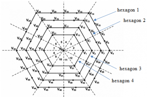
Depending on the states of the inverter switches, this vector can take several positions in the d−q plane. These positions are shown on the vector diagram in Figure 10. There are 60 discrete positions, distributed over four hexagons, in addition to a position in the center of the hexagon. Some positions are created by several redundant states. From the external hexagon towards the internal hexagon, the positions of the vector Vs are created respectively by one, two, three or four redundant states. The position of the center of the hexagon, which corresponds to a zero output voltage, is created by five redundant states. There are thus 24 positions with a single redundancy (hexagon 1), 18 positions with two redundancies (hexagon 2), 12 positions with three redundancies (hexagon 3) and 6 positions with four redundancies (hexagon 4) (Figure 11).
Figure 10. Five-level inverter vector diagram
Figure 11. Hexagons of 5LI space vector diagram
The voltages of capacitors Vdc1 and Vdc2 (Figure 5) are balanced by the control of the 3LB, but the voltages of capacitors Uc1, Uc2, Uc3, Uc4 and Uc4 are not equal. We use two balancing bridges to make them at equal value.
$V_{d c 1}=U_{c 1}+U_{c 2}$ (12)
$V_{d c 2}=U_{c 3}+U_{c 4}$ (13)
7.1 Capacitor voltage balancing of three-level boost
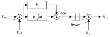
Various works have been carried out in order to maintain the equality of the voltage values of the two capacitors of the 3LB. To achieve this goal, Krishna et al. [16] in his two-stage conversion cascade composed by a 3LB and a three-level inverter uses two PI regulators. Another work presented in the ref. [24] introduces a PI and fuzzy logic regulators. In this work, we use only a single PI regulator for the regulation of the voltages of the two capacitors (Figure 12). D2 is the control order of the second transistor of the 3LB.
Figure 12. 3LB regulation loop
7.2 Clamping bridge
The clamping bridge consists of a transistor and a resistor connected in parallel with the capacitor whose voltage is unbalanced, as shown in Figure 13. In our case, we introduce two clamping bridges in parallel with capacitors Uc1 and Uc4 (Figure 5). Its mathematical model is:
$C_i \frac{d U_{c i}}{d t}=I_{\text {redi }}+i_{r(i+1)}+i_{c(i+1)}-i_{d i}-i_{r i}$ (14)
$i_{r i}=T_i \frac{U_{c i}}{R_{p i}}$ (15)
Figure 13. Clamping bridge cell structure
The balancing bridge through its algorithm removes energy from the capacitor with the highest voltage and then transfers that energy to the capacitor with the lowest voltage until the voltage is equalized across all capacitors. The control algorithm used is as follows.
$\left\{\begin{array}{l}U_{c i}-U_{c r e f}=\varepsilon_i \\ \text { if } \varepsilon_i \geq 0 \text { we have } T_i=1 \Rightarrow i_{r i}=T_i \frac{U_{c i}}{R_{p i}} \\ \text { if } \varepsilon_i \leq 0 \text { we have } T_i=0 \Rightarrow i_{r i}=0\end{array}\right.$ (16)
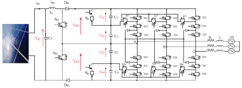
The photovoltaic conversion cascade is shown in Figure 14. We use Matlab simulink software to simulate our system. The solar radiation applied to the photovoltaic generator is fixed at Ray=1000 W/m2. The reference DC bus voltage is Vdcref=650V.
Figure 14. PV generator-Three-level boost converter-5LI-Grid
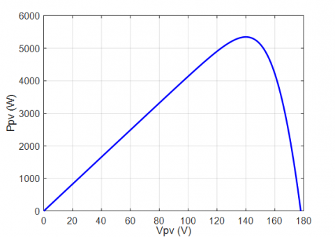
The P(V) characteristic of the photovoltaic generator composed of 20 solar modules of 270W (four in series and five in parallel) each one with Vmpp=35V and Impp=7.7A is shown in Figure 15. We note that the maximum power that the photovoltaic generator can deliver is 5400 W.
Figure 15. P(V) Characteristic of the photovoltaic generator
Figure 16 presents the voltage Vpv, the current Ipv and the power Ppv of the photovoltaic generator. We notice that the voltage at the point of maximum power is 140V and the power is 5400 W. So the fuzzy logic-based MPPT algorithm works correctly.
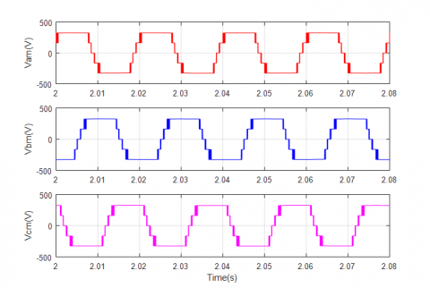
Figure 17 shows the voltage of the three legs of the five-level inverter. The waveform obtained clearly presents the five voltage levels, which proves the effectiveness of the applied space vector modulation algorithm.
Figure 18.a presents the sum of the voltages Vdc1 and Vdc2. This value of the global bus voltage is regulated by the control of the inverter where the value obtained is equal to the value of the reference voltage imposed in the control loop of 5LI.
Figure 16. Voltage Vpv(V), Current Ipv(A), Power Ppv(W) of the photovoltaic generator
Figure 17. Three legs voltages of 5LI
After imposing the global bus voltage by the control of the inverter, the 3LB will also ensure by its control, in addition to extracting the maximum power from the photovoltaic generator, the maintaining equality of the voltages Vdc1 and Vdc2. Figure 18.b shows that the output voltages of the 3LB are of equal values.
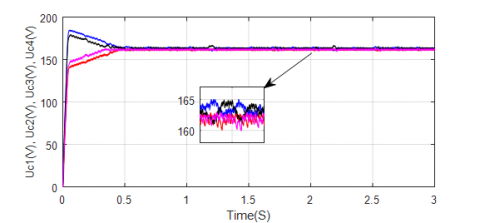
The four voltages of the capacitors Uc1, Uc2, Uc3, and Uc4 are presented in Figure 19. The control of the 3LB ensures that the value of the sum of the voltages Uc1+Uc2 and Uc3+Uc4 is maintained, but the NPC structure of the inverter used does not make it possible to maintain the equality of the voltages Uc1 and Uc2 as well as Uc3 and Uc4. In this case, the two balancing bridges introduced into the DC bus intervene to balance and maintain the equality between the voltages Uc1 and Uc2 as well as Uc3 and Uc4.
The result obtained shows the efficiency of the proposed solution to maintain equal the four bus voltages of this cascade.
Figure 18. (a) Voltage Vdc1 + Vdc2, (b) Voltages Vdc1 and Vdc2 of 3LB
Figure 19. Capacitor voltages Uc1(V), Uc2(V), Uc3(V), Uc4(V)
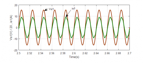
Figure 20. Voltage and current of grid
With four balanced capacitor voltages, we get symmetrical inverter output voltage waveforms, which directly affects the current output waveform. Figure 20 shows the voltage and current of the first phase of the grid. We note from the result that the control of the 5LI allowed injecting into the grid a current in phase with the grid voltage.
This article presents a new configuration of a two-stage photovoltaic conversion cascade interconnected to the grid based on 3LB and 5LI, with a DC Bus voltage balancing solution adapted to this configuration.
The proposed solution is able to regulate and maintain stable the four DC bus capacitor voltages. The regulation of the global bus voltage is ensured by the control of the multilevel inverter by the method of synchronous reference frame control. This overall voltage is divided into two equal voltages by the 3LB control, which at the same time ensures, via a fuzzy regulator, the extraction of the maximum power from the photovoltaic generator. Therefore, in our case there is the problem of voltages imbalance caused by the 5LI.
We have proposed to solve this problem, the introduction of two CBs, each one composed of a transistor in series with a resistor.
These CBs were introduced in parallel with two DC bus capacitors. The results obtained by simulation present:
With four balanced capacitor voltages, we obtained symmetrical inverter output voltage waveforms and a good quality of the current injected to the grid.
This project was financially supported by the Directorate General for Scientific Research and Technological Development - Algerian Ministry of Higher Education and Scientific Research.
[1] Nabae, A., Takahashi, I., Akagi, H. (1981). A new neutral-point clamped PWM inverter. IEEE Transactions on Industry Applications, 5: 518-523. https://doi.org/10.1109/TIA.1981.4503992
[2] Choi, U.M., Lee, J.S. (2021). Single-phase five-level IT-type NPC inverter with improved efficiency and reliability in photovoltaic systems. IEEE Journal of Emerging and Selected Topics in Power Electronics. https://doi.org/10.1109/JESTPE.2021.3103252
[3] Ganjavi, A., Ghoreishy, H., Ahmad, A. (2018). A novel single-input dual-output three-level DC-DC converter. IEEE Transactions on Industrial Electronics, 65(10): 8101-8111. https://doi.org/10.1109/TIE.2018.2807384
[4] Arezki, S., Boudour, M. (2014). DC bus voltage balancing of multi-inverter in photovoltaic system. In 2014 16th International Power Electronics and Motion Control Conference and Exposition, pp. 1059-1065. https://doi.org/10.1109/EPEPEMC.2014.6980649.
[5] Benamrane, K., Abdelkrim, T., Borni, A., Benslimane, T., Abdelkhalek, O. (2016). Stability study of output voltages of stand alone single stage NPC seven levels inverter for PV system in South Algeria. In 8th International Conference on Modelling, Identification and Control (ICMIC 2016), pp. 654-659. https://doi.org/10.1109/ICMIC.2016.7804193
[6] Arezki, S., Boudour, M. (2012). Solutions to the instability problem of the DC input voltages of neutral point clamping multilevel inverter in photovoltaic chain connected to the network. In 2012 2nd International Symposium on Environment Friendly Energies and Applications, pp. 13-19. https://doi.org/10.1109/EFEA.2012.6294088
[7] Belabbas, B., Denai, M., Allaoui., T. (2020). A hierarchical control scheme to improve the stability and energy quality of a hybrid wind / photovoltaic system connected to the electricity grid. University Politehnica of Bucharest Scientific Bulletin Series C-Electrical Engineering and Computer Science, 82: 307-323. https://www.scientificbulletin.upb.ro/rev_docs_arhiva/fullf2a_329239.pdf.
[8] Palanisamy, R., Shanmugasundaram, V., Vidyasagar, S., Kalyanasundaram, V., Vijayakumar, K. (2020). A SVPWM control strategy for capacitor voltage balancing of flying capacitor based 4-level NPC inverter. Journal of Electrical Engineering & Technology, 15(6): 2639-2649. https://doi.org/10.1007/s42835-020-00533-3
[9] Bahri, A., Thameur, A., Mordjaoui, M., Bechouat, M., Sedraoui, M. (2021). An optimal tilt integral derivative applied to the regulation of DC link voltage in a stand-alone hybrid energy system. Journal Européen des Systèmes Automatisés, 54(4): 607-616. https://doi.org/10.18280/jesa.540410
[10] Thameur, A., Noureddine, B., Abdelhalim, B., Boualam, B., Abdelkader, L., Karima, B., Tarak, B. (2020). Particle swarm optimization of pi controllers in grid-connected PV conversion cascade based three levels NPC inverter. In 2020 IEEE International Conference on Environment and Electrical Engineering and 2020 IEEE Industrial and Commercial Power Systems Europe (EEEIC/I&CPS Europe), pp. 1-5. https://doi.org/10.1109/EEEIC/ICPSEurope49358.2020.9160704
[11] Ravi, A., Manoharan, P.S., Anand, J.V. (2011). Modeling and simulation of three phase multilevel inverter for grid connected photovoltaic systems. Solar Energy, 85(11): 2811-2818. https://doi.org/10.1016/j.solener.2011.08.020
[12] Rajkumar, M.V., Manoharan, P.S., Ravi, A. (2013). Simulation and an experimental investigation of SVPWM technique on a multilevel voltage source inverter for photovoltaic systems. International Journal of Electrical Power & Energy Systems, 52: 116-131. http://dx.doi.org/10.1016/j.ijepes.2013.03.022
[13] Thirumurugan, P., Preethi, R., Sangeetha, B. (2013). Comparison of closed loop control for three-level and five-level inverter for photovoltaic system. In 2013 International Conference on Communication and Signal Processing, pp. 240-244. https://doi.org/10.1109/iccsp.2013.6577051
[14] Badoud, A., Khemliche, M., Bacha, S., Raison, B. (2013). Modeling and performance analysis of multilevel inverter for single-phase grid connected photovoltaic modules. In 2013 International Renewable and Sustainable Energy Conference (IRSEC), pp. 171-176. https://doi.org/10.1109/IRSEC.2013.6529727
[15] Yang, Y., Wen, H. (2019). Adaptive perturb and observe maximum power point tracking with current predictive and decoupled power control for grid-connected photovoltaic inverters. Journal of Modern Power Systems and Clean Energy, 7(2): 422-432. https://doi.org/10.1007/s40565-018-0437-x
[16] Krishna, R., Soman, D.E., Kottayil, S.K., Leijon, M. (2015). Pulse delay control for capacitor voltage balancing in a three‐level boost neutral point clamped inverter. IET Power Electronics, 8(2): 268-277. https://doi.org/10.1049/iet-pel.2014.0103
[17] Benamrane, K., Abdelkrim, T., Benlahbib, B., Bouarroudj, N., Borni, A., Lakhdari, A., Bahri, A. (2021). New optimized control of cascaded multilevel converters for grid tied photovoltaic power generation. Journal Européen Des Systèmes Automatisés, 54(5): 769-776. https://doi.org/10.18280/jesa.540512
[18] Sarthi, P., Rao, A.M., SivaKumar, K. (2017). Analysis for optimal distribution of PV panels and batteries in multilevel inverters. In 2017 National Power Electronics Conference (NPEC), pp. 240-245. https://doi.org/10.1109/NPEC.2017.8310465
[19] Laib, A., Krim, F., Talbi, B., Sahli, A. (2020). A predictive control scheme for large-scale grid-connected PV system using high-level NPC inverter. Arabian Journal for Science and Engineering, 45(3): 1685-1701. https://doi.org/10.1007/s13369-019-04182-1
[20] Abdullah, R., Rahim, N.A., Raihan, S.R.S., Ahmad, A.Z. (2014). Five-level diode-clamped inverter with three-level boost converter. IEEE Transactions on Industrial Electronics, 61(10): 5155-5163. https://doi.org/10.1109/TIE.2013.2297315
[21] de Britto Florencio, R., Bellar, M.D., Bento, A.A. (2018). Solar PV energy system based on series interleaved three-level boost converter and five-level MLC 2 inverter. In 2018 7th International Conference on Renewable Energy Research and Applications (ICRERA), pp. 1227-1232. https://doi.org/10.1109/ICRERA.2018.8566774
[22] Huang, B., Sadli, I., Martin, J.P., Davat, B. (2006). Design of a high power, high step-up non-isolated dc-dc converter for fuel cell applications. In 2006 IEEE Vehicle Power and Propulsion Conference, pp. 1-6. https://doi.org/10.1109/VPPC.2006.364324
[23] Said, B., Omar, O., i Cabarrocas, P.R., Mahmoud, B. (2015). Modeling and control of a five level inverter used with renewable enery sources. In 2015 3rd International Conference on Control, Engineering & Information Technology (CEIT), pp. 1-5. https://doi.org/10.1109/CEIT.2015.7233156
[24] Nouri, A., Salhi, I., Elwarraki, E., El Beid, S., Essounbouli, N. (2017). DSP-based implementation of a self-tuning fuzzy controller for three-level boost converter. Electric power systems Research, 146: 286-297. http://dx.doi.org/10.1016/j.epsr.2017.01.036