Abdelkader Bendriss* | Lakhdar Aidaoui | Miloud Tahar Abbes
© 2022 IIETA. This article is published by IIETA and is licensed under the CC BY 4.0 license (http://creativecommons.org/licenses/by/4.0/).
OPEN ACCESS
Foundation excavation and general earthworks are activities that involve the machine operator in a series of repetitive and tedious operations, suggesting opportunities for automation through by the introduction of robotic technologies with subsequent improvements in the design and machine use, especially, in dangerous environments working. Automation of excavation operations can be realized by an automatically controlled excavator system that is able to perform autonomously a planned digging work. In this study, a modeling of an excavation mechanism has been represented, where the purpose is to automatically excavate a parallelepiped-shaped foundation. From existing excavation machinery in the industry, the manipulator arm of a backhoe was chosen to do the modeling. Starting from the basic input geometric parameters of the foundation to be excavated, the system gives as outputs results: A simulation of the various mechanism components movement, in addition to the automatic excavation trajectory of the parallelepiped foundation. Finally, from the soils properties of the western region of Algeria that they were measured experimentally, a resistance simulation of the various components of the mechanism was carried, to test the reliability of the mechanism in terms of deformation and Von Mises stress.
simulation, mechanism, excavation, automation
The realization of public works and civil engineering projects requires special machines capable to carrying out specific works with less effort and in short times. Advances in technology tend towards the automation of earth excavation machinery, in order to prove that the modeled excavator mechanism must work reliably under unpredictable working conditions. Thus, it is necessary for the designers to provide not only an equipment of maximum reliability but also of minimum weight and cost, keeping design safe under all loading conditions. Furthermore, the automation of the earth removal process is also likely to provide a number of other benefits, such as, a reduced dependence on operator skills and a lower operator workload, both of which might be expected to contribute to the improvements in quality, in particular, the removal of the need for a local operator when working in hazardous environments.
The development of such an automated control system is usually based on a model that describes motion in real time. A kinematic and dynamic model for an excavator is necessary for the design of the controller. This model can be obtained by: applying the Newton-Euler equations for each link of the mechanism successively [1, 2], where the motion equation is derived; or by integration of the soil-tool interaction model [3, 4], in order to take into account, the reaction force of the soils.
An experimental approach to determine the links parameters (related to mass and inertia) and friction coefficients is developed for a manipulator arm of an excavator [5]. The complete set of inertia and friction parameters is identified by applying the least squares method to the experimental data collected during the displacement of the links by a tele-operated control of the machine [5, 6]. In a similar study, a tele-operated system was developed for the manipulator arm of an excavator, the sensors are attached to the arm to detect its movement, the actuators transmit wireless communications via Bluetooth [7, 8], or by a TCP/IP protocol [9]. Other techniques use a joystick for the coordinated position control (CPC) of the excavator arm, the CPC is obtained using a joystick whose kinematics is similar to the arm movement of the excavator [10, 11]. The rest of the techniques use rules-based intelligent automatic control, to control the bucket tip of an excavator arm [12-16], or for full system automation that automates the task of excavation and soil clearance [17].
The design of the excavator manipulator arm is one of the most important tasks for our study. The arm must work reliably in various working conditions with high loads. It is therefore necessary to design equipment that has maximum reliability and minimum weight, keeping the design safe under all load conditions. The structural modification of the weight of the excavator arm by improving the design or by changing the material. Detailed investigation was carried out by finite element analysis using a numerical simulation software to understand the stress developed in the arm for all design considerations. Modeling is performed by changing the shape of the arms [18-20], modifying the material of construction [21, 22], or by changing both them [23]. A finite element analysis of cutting teeth in which the linear increase in lateral force is taken into account [24]. While, other studies are interested in improving the energy system and the performance of the components of the manipulator arm to increase the performance and power of the excavation machine [25, 26].
The soil parameters and the soil-tool interaction forces exerted during the excavation operation should be found before the excavation operation. These forces are useful for better design of the tool, parts of the excavator and also for the arm path planning. Many researchers achieved studied in the same field which includes the fundamentals of soil mechanics, soil-tool interaction forces, and various parameters affecting the soil-tool interaction during its digging action [27, 28]. Due to the insufficiency or absence of excavators which can excavate parallelepiped-shaped foundations, especially in places where working conditions are difficult (narrow places, places where the ground is unstable, Inclined or sloping places, etc.). The objective of the present study is the modulation of a mechanism capable of automatically excavating a parallelepiped-shape foundation in any working place. This area is open to perform further research to know the effect of various parameters on soil-tool interaction, prediction of digging trajectory and excavation forces and for the robust design of the mechanism of backhoes which is in general the subject of the present work.
Through research presented, it can be said that most research in this field has focused on certain parts of the problem either by experimentation or by numerical analysis, for example studying the kinematic or dynamic movement of the excavator, treatment of the autonomous control problem of excavator by various automatic control technologies, and soil-tool interaction analysis. This article presents a system that completely automates the operation of excavating a parallelepiped-shaped foundation, the application can be extended to the construction of buildings or individual houses foundations; this involves the structural modification of the manipulator arm dimensions of a backhoe for the design by simulation of a mechanism (mini-excavator), the purpose of which excavate in narrow places.
In this study, a modeling of a manipulator arm of a backhoe with reduced dimensions was modeled. Indeed, the use of automation opportunities becomes essential, thanks to the introduction of robotic technologies, especially when working in hazardous environments. Starting from the geometric parameters of the foundation to be excavated, the system gives as an output the trajectory of the parallelepipedal-shape foundation to be excavated automatically, through a kinematic study of the mechanism, as well as the resistance of the mechanism according to the properties of the Algerian soil. The obtained results show the three-dimensional positioning of the various joints of the mini manipulator arm modeled according to: the angles of rotation, a reference point, as well as the automatic excavation trajectory of the parallelepiped-shape foundation, also a resistance simulation of the various components of the modeled excavation mechanism.
In the industry, there are many excavation machines, where each machine has a specific domain of use. Several factors can influence the choice of an excavator, including the size and shape of the foundation, the nature of the terrain (flat or sloping surface), the properties of the soil, as well as the excavation method. According to the excavation method, this equipment can first be classified into two categories, surface excavation and underground excavation. Surface excavation machines are in turn divided into two categories, rotary machines and cyclic machines.
Rotary digging machines are classified into two categories trenchers and drills. The trenchers are mainly used in the installation of telephone cables, as well as all operations requiring trenches of small width and great length, trenchers are characterized by the speed of excavation. While drilling rigs are mainly used in the drilling of wells, as well as all operations requiring the drilling of an artesian well or a vertical pit.
Cyclic excavation machines are classified into five categories (charger, grader, dragline, cable shovel, and backhoes). Chargers are used in operations that require the clearing or moving of soil. Graders are used in road works. Draglines are used in mining works. Cable shovels are similar to draglines but with a large amount of soil to excavate. Backhoes are the machines most commonly used to excavate foundations or trenches.
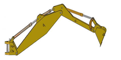
After the explanation of the field of use of each machine. We can choose the machine most adopted in our case; excavation of the foundations, which ensures the parallelepiped geometry of the pit, and which can move in three dimensions. This machine is the backhoe, which has a mechanism composed of four elements (a. cabin-swing; b. boom; c. arm; and d. bucket) (Figure 1).
Figure 1. The excavation mechanism selected
The analytical description of the spatial movement of the excavation mechanism is the main objective of the kinematic study, in particular the relationship between the positions of the joints of the manipulator arm and the profile of the pit. There are two fundamental problems to be solved by kinematics: forward kinematics and backward (reverse) kinematics. The excavator is presented as a manipulator robot with 4 degrees of freedom.
3.1 Forward kinematics relations
To describe the direct kinematic model, we used the methodology of Denavit-Hartenberg (DH) [1]. The determination of the DH parameters must be obtained by placing the manipulator arm in its initial position (O0), then for almost each joint a landmark is assigned according to the type of link.
From Figure 2, Table 1 summarizes the values of the DH parameters for the manipulator arm of the modeled mechanism.
Figure 2. Kinematic diagram of the manipulator arm according to Denavit-Hartenberg methodology
Table 1. Values of the DH parameters for the manipulator arm modeled
|
Link |
Torsion angle αi |
Link length ai |
Eccentric length di |
Rotation angle θi |
|
1 |
90° |
a1=l1 |
0 |
θ1 |
|
2 |
0° |
a2=l2 |
0 |
θ2 |
|
3 |
0° |
a3=l3 |
0 |
θ3 |
|
4 |
0° |
a4=l4 |
0 |
θ4 |
Note: the parameters of the table (DH) are defined as follows: 1. αi : Rotation angle of relative to the X(i) axis; 2. ai : Distance between Z (i-1) to Z(i), in relation to the X (i-1) or Y (i-1) axis; 3. di : Distance from X (i-1) to X(i) (Y (i-1) to Y (i)), with respect to the Z(i-1) axis; 4. θi : Angle of rotation with respect to the Z(i-1) axis.
From the previous table, the transformation matrices ($A_{i-1}^i$) which connect two adjacent coordinate landmarks are given by:
$A=\left[\begin{array}{cc}R_{3 \times 3} & P_{3 \times 1} \\ f_{1 \times 3} & W_{1 \times 1}\end{array}\right]=\left[\begin{array}{cc}\text { Rotation } & \text { Translation } \\ \text { Perspective } & \text { scale }\end{array}\right]$ (1)
The general transformation matrix is given by Eq. (2).
$A_{i-1}^i=\left[\begin{array}{cccc}\cos \theta_i & -\cos \alpha_i \sin \theta_i & \sin \alpha_i \sin \theta_i & a_i \cos \theta_i \\ \sin \theta_i & \cos \alpha_i \cos \theta_i & -\sin \alpha_i \cos \theta_i & a_i \sin \theta_i \\ 0 & \sin \alpha_i & \cos \alpha_i & d_i \\ 0 & 0 & 0 & 1\end{array}\right]$ (2)
The transformation matrix of link O0 to link O1 is given by Eq. (3).
$A_0^1=\left[\begin{array}{cccc}\cos \theta_1 & 0 & \sin \theta_1 & a_1 \cos \theta_1 \\ \sin \theta_1 & 0 & -\cos \theta_1 & a_1 \sin \theta_1 \\ 0 & 1 & 0 & 0 \\ 0 & 0 & 0 & 1\end{array}\right]$ (3)
The transformation matrix of link O1 to link O2 is given by Eq. (4).
$A_1^2=\left[\begin{array}{cccc}\cos \theta_2 & -\sin \theta_2 & 0 & a_2 \cos \theta_2 \\ \sin \theta_2 & \cos \theta_2 & 0 & a_2 \sin \theta_2 \\ 0 & 0 & 1 & 0 \\ 0 & 0 & 0 & 1\end{array}\right]$ (4)
The transformation matrix of link O2 to link O3 is given by Eq. (5).
$A_2^3=\left[\begin{array}{cccc}\cos \theta_3 & -\sin \theta_3 & 0 & a_3 \cos \theta_3 \\ \sin \theta_3 & \cos \theta_3 & 0 & a_3 \sin \theta_3 \\ 0 & 0 & 1 & 0 \\ 0 & 0 & 0 & 1\end{array}\right]$ (5)
The transformation matrix of link O3 to link O4 is given by Eq. (6).
$A_3^4=\left[\begin{array}{cccc}\cos \theta_4 & -\sin \theta_4 & 0 & a_4 \cos \theta_4 \\ \sin \theta_4 & \cos \theta_4 & 0 & a_4 \sin \theta_4 \\ 0 & 0 & 1 & 0 \\ 0 & 0 & 0 & 1\end{array}\right]$ (6)
3.1.1 Calculation of the joints positions of the mechanism
The model for calculating the position of the various joints of the mechanism is solved using the kinematic study, as follows:
Point O1 is the link joint between the mechanism control and the boom. The position of this point is determined by:
$P o_1=A_0^1 P o_0$ with $P o_0=[0,0,0,1]^T$ (7)
Substituting Eq. (3) into Eq. (7) gives the position of the point Po1{X1, Y1, Z1}:
$\left\{\begin{array}{l}O_{1 x}=a_1 \cos \theta_1 \\ O_{1 y}=a_1 \sin \theta_1 \\ O_{1 z}=0\end{array}\right.$ (8)
Point 2 is the link joint between the boom and the arm of the mechanism. The position of this point is determined by:
$P o_2=A_1^2 P o_1=A_0^1 A_1^2 P o_0$ (9)
Substituting Eq. (4) and Eq. (8) into Eq. (9) gives the position of the point Po2{X2, Y2, Z2}:
$\left\{\begin{array}{l}O_{2 x}=\cos \theta_1\left(a_2 \times \cos \theta_2+a_1\right) \\ O_{2 y}=\sin \theta_1\left(a_2 \times \cos \theta_2+a_1\right) \\ O_{2 z}=a_2 \times \sin \theta_2\end{array}\right.$ (10)
Point 3 is the link joint between the arm and the bucket of the mechanism. The position of this point is determined by:
$P o_3=A_2^3 P o_2=A_1^2 A_2^3 P o_1=A_0^1 A_1^2 A_2^3 P o_0$ (11)
So
$\left\{\begin{array}{l}O_{3 x}=\cos \theta_1\left(a_3 \times \cos \left(\theta_2+\theta_3\right)+a_2 \times \cos \theta_2+a_1\right) \\ O_{3 y}=\sin \theta_1\left(a_3 \times \cos \left(\theta_2+\theta_3\right)+a_2 \times \cos \theta_2+a_1\right) \\ O_{3 z}=a_3 \times \sin \left(\theta_2+\theta_3\right)+a_2 \times \sin \theta_2\end{array}\right.$ (12)
Point 4 is the end of the bucket, the position of this point is given by the Eq. (13).
$\left\{\begin{array}{l}O_{4 x}=\cos \theta_1\left(\begin{array}{l}a_4 \times \cos \left(\theta_2+\theta_3+\theta_4\right)+a_3 \times \cos \left(\theta_2+\theta_3\right)+ \\ a_2 \times \cos \theta_2+a_1\end{array}\right) \\ O_{4 y}=\sin \theta_1\left(\begin{array}{l}a_4 \times \cos \left(\theta_2+\theta_3+\theta_4\right)+a_3 \times \cos \left(\theta_2+\theta_3\right) \\ +a_2 \times \cos \theta_2+a_1\end{array}\right) \\ O_{4 z}=a_4 \times \sin \left(\theta_2+\theta_3+\theta_4\right)+a_3 \times \sin \left(\theta_2+\theta_3\right)+a_2 \times \sin \theta_2\end{array}\right.$ (13)
3.2 Backward kinematics relations
Backward (reverse) kinematics equations are used to determine joint rotation angles from a reference point (O3=D) with $P_0^D=\left[\begin{array}{lll}P_{0 X}^D & P_{0 Y}^D & P_{0 Z}^D\end{array}\right]^T$.
$\theta_1=\tan ^{-1}\left(\frac{P_{0 Y}^D}{P_{0 X}^D}\right)$ (14)
$\theta_2=\cos ^{-1}\left(\frac{\left(P_{0 Z}^D\right)^2+d^2+a_2^2-a_3^2}{r}\right)+\tan ^{-1}\left(P_{0 Z}^D / d\right)$ (15)
with, $d=\cos \theta_1 P_{0 X}^D+\sin \theta_1 P_{0 Y}^D-a_1$; $r=\left\{4 a_2^2 \times\left[d^2+\left(P_{0 Z}^D\right)^2\right]\right\}^{1 / 2}$.
$\theta_3=\sin ^{-1}\left(\frac{-\sin \theta_2\left(\cos \theta_1 p_{0 X}^D+\sin \theta_1 p_{0 Y}^D-a_1\right)+\left(\cos \theta_2\right) p_{0 Z}^D}{a_3}\quad\right)$ (16)
$\theta_4=\theta_{s g}+\left(2 \pi-\theta_2-\theta_3\right)$ (17)
The excavation of the foundation is given by the positioning of point O4, i.e. the end of the bucket. The rotation angle of the bucket has an essential role in our application, in the first step we assumed that the bucket and the ground plane of the foundation to excavate form an angle of (π/2), from the Figure 3, we can deduce the entry angle of the bucket θ4=-( 3π/4+θ2+θ3). All these steps are represented in detail by the general flowchart of automatic excavation of the parallelepiped foundation.
Figure 3. Mechanism links rotation angles
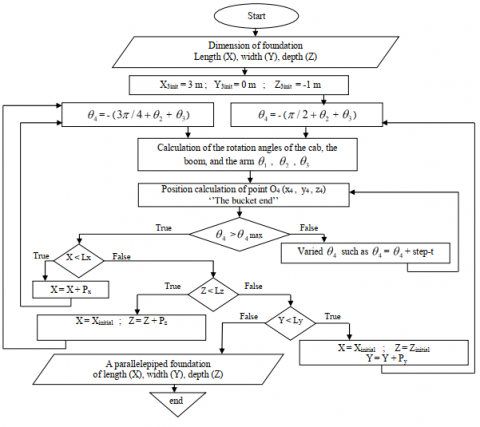
The calculation of the automatic excavation trajectory of the parallelepiped-shaped foundation is obtained by programming the flowchart of Figure 4. The reference point O3 has the coordinates (X3=3 m, Y3=0 m, Z3=-1 m), since the distance between the point of origin of the mechanism and the ground level is assumed to be 1 m along to the Z axis. The calculation of the angles θ1, θ2, θ3, θ4 is carried out by programming Eq. (14), Eq. (15), Eq. (16) and Eq. (17) respectively, moreover the calculation of the end bucket point of the mechnism is carried out by the programming of Eq. (13), these steps are represented on the flow chart of Figure 4.
Figure 4. Flowchart of the automatic foundation excavation
Our work consists in the implementation of a system capable to automatically excavate a parallelepiped-shaped foundation. The study is essentially based on the movement of the manipulator arm of a backhoe, for determining the excavation trajectory of the parallelepiped foundation.
5.1 Kinematic modeling
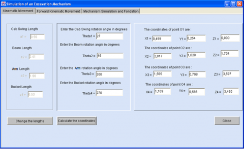
The direct kinematics equations are used to determine the positions of joints links points as a function of the rotation angles of the components of the mechanism. While the backward kinematics equations are used to determine the rotation angles of the mechanism components as a function of a reference point, in our application the reference point is the point O3 (joint link point between arm and bucket). Figure 5 represents the graphical interface for calculating the kinematic motion of the modeled excavation mechanism.
Figure 5 represents a graphic interface of the calculation of all the articulation points of the modeled mechanism. Remember: point O1 the link between the swing-cab and the boom, point O2 the link between the boom and the arm, point O3 the connection between the arm and the bucket. This involves programming Eq. (8), Eq. (10), Eq. (12) and Eq. (13).
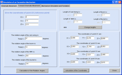
Figure 6 represents a graphic interface of the calculation of the backward kinematic movement; these results are obtained by the programming of the Eq. (15), Eq. (16) and Eq. (17).
Figure 5. Program interface of forward kinematic motion
Figure 6. Program interface of backward kinematic motion
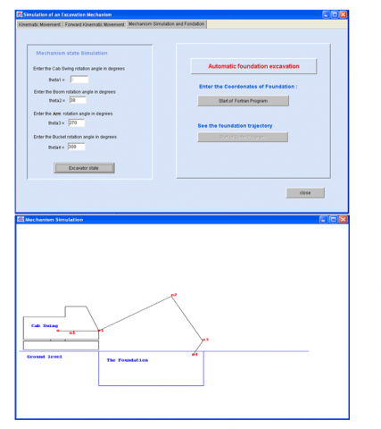
5.2 Mechanism simulation
Figure 7. Simulation of the manipulator arm in the condition of excavation
From previous studies it is also possible to simulate the positions of the various components of the excavation mechanism, in particular the positions of the points of link in four degrees of freedom, that is to say, the system has in input the angles of rotation of each component of the mechanism (boom, arm, bucket) in degrees, and on output the system determines the positions of the link points of the joints of the mechanism according to these angles. Figure 7 presents the graphical interface of the state simulation of the mechanism in two dimensions (2D) since the angle of rotation of the cab-swing is assumed to be constant (θ1=0), therefore the mechanism is simulated in the plane ($\vec{X}, \vec{Z}$).
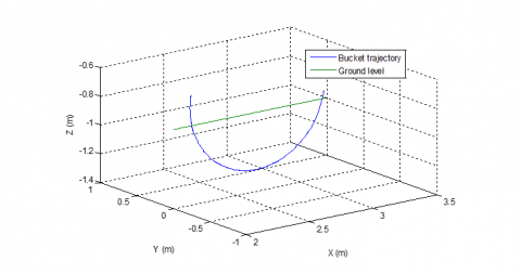
5.3 Modeling of the excavation operation
The modeling of the excavation operation is the simulation of the trajectories of the bucket end of the manipulator arm of the mechanism (O4). The bucket and the arm have a fundamental role in the automatic excavation of the foundations, on which the modeling of the automatic excavation system is based, while the cab-swing and the boom have a primordial role in the clearing of the excavated soil. Figure 8 shows a simulation of the trajectory of the bucket end, by rotation of the bucket.
Figure 8. Simulation of bucket trajectory
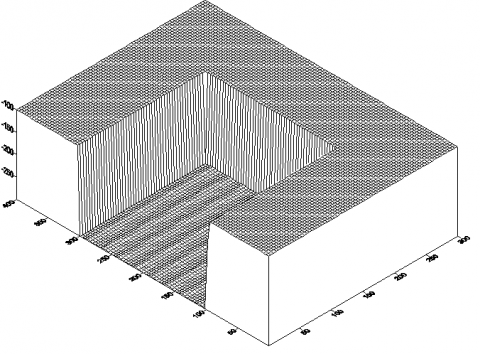
5.4 Simulation of automatic excavation
To simulate the automatic excavation of the foundation parallelepiped shape with the desired dimensions, the flowchart of the Figure 4 was used, in which the foundation is considered as a volume where it was subdivided into sub volume and each sub-volume represents an excavation step. The height of the mechanism cab is assumed to be 1 m above the ground level. The excavation operation starts with a reference point (Dx=3 m; Dy=0 m; Dz=-1 m) in the plane ($\vec{X}, \vec{Z}$), if the dimensions (length, depth) are reached in this plane, the system increments one step along the width (the $\vec{Y}$ axis) and repeats the previous procedure until the dimensions (length, width, depth) of the foundation are reached (Figure 4). The results of the simulation of the foundation parallelepiped shape are represented by Figure 9.
5.5 Mechanism resistance simulation
To test the resistance of the mechanism to Von Mises stress and deformation, firstly, the four components of the mechanism (cab-swing, boom, arm, bucket) were modeled numerically using an alloy steel design material, which has the following characteristics: Yong's modulus=22.1010 Pa; the Poisson's ratio=0.285; and a density of 7850 kg/m3.
(a) A parallelepiped foundation of Length=1m; Width=1m and Depth=1m
(b) A parallelepiped foundation of Length=2m; Width=2m and Depth=2m
Figure 9. Simulation of the foundation parallelepiped shape
But before representing the results of the mechanism resistance, it is necessary to know the properties of the soil on which we will test the behavior of the mechanism components.
5.5.1 Soil properties
The studies of the soils were carried out in the western region of Algeria is an area of complex relief where there are plains, plateaus, mountains and coasts. To properly carry out this study, several core drillings and about ten heavy dynamic penetrometer tests were programmed, in order to make a description and an identification of the geological horizons and also a determination of the geotechnical parameters of the soil. According to the Laboratory of Housing and Construction-West subsidiary (LHCW), the soil properties of the western region of Algeria can be summarized in:
Table 2. Soil properties of the Algeria western region
|
Type of soil |
Bulk density [t/m3] |
Anchor depth [m] |
Allowable shear stress [bars] |
|
Argil (Clay) |
1.65 to 1.83 |
2.8 to 3.2 |
1.2 |
|
Silty argil |
1.57 to 1.72 |
1.8 to 2.8 |
0.8 to 1.6 |
|
Sandy silty argil |
1.69 to 1.82 |
2.4 to 2.6 |
0.66 to 1.4 |
|
Tuff |
1.79 |
2 |
1.5 |
|
Clayey Tuff |
1.81 |
1.8 |
1.4 |
|
Yellowish calcareous sandstone |
2.34 |
1.6 |
2 |
|
Loam |
|
2 |
1.4 |
|
Sandstone sand |
|
2 |
2.66 |
From the Table 2, it can be seen that the most resistant soil in the western region of Algeria has an allowable stress of almost 2.7 bar. For this purpose, we tested the modeled mechanism at different stresses (between 0.7 bars and 4.5 bars), the principle of choosing 4.5 bars is that the resistance of certain types of clay soil can reach this value. In addition, to properly test the reliability of the mechanism in terms of resistance.
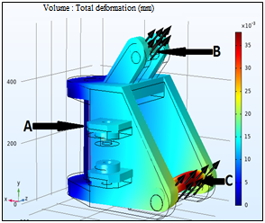
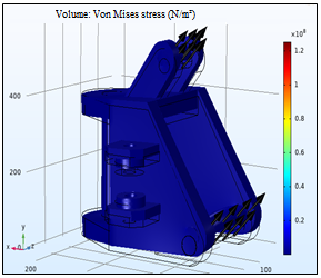
5.5.2 The resistance of the cab-swing
The swing-cab (base of the manipulator arm) has been designed with the following measurements: length 579.19 mm, width 355 mm, and height 573.13 mm. Figure 10 shows the resistance simulation results of the Von Mises stress and deformation of the cab-swing (base of the mechanism) according to the nature of the Algerian soil. The results are represented in two stress values of 4.5 bars and 1.5 bars. To carry out the study, we applied an embedding at point A of the swing-cab, and we applied stresses on the borders at points B and C. For a stress of 4.5 bars (450000 N/m2) applied to regions B and C, the Figure 10a and Figure 10b show maximum bending deformation around 35.10-3 mm and maximum Von Mises stress around 25.106 N/m2 respectively. However, with a stress of 1.5 bars Figure 10c and Figure 10d show a maximum bending deformation of 12.mm and a maximum Von Mises stress of 10.106 N/m2. From this results, it was found that the cab-swing of the modeled mechanism supports the applied stress in terms of resistive Von Mises stress and bending deformation.
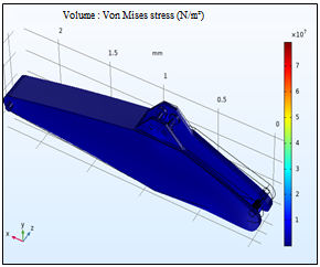
5.5.3 The resistance of the boom
To test the resistance of Von Mises stress and deformation, firstly, the boom was designed with the following measurements: length 2412.1 mm, width 253 mm, and height 637.60 mm. Subsequently, the same steps as the previous application were followed by the use of a numerical model with the application of two different stress values 4.5 bars and 3 bars. As shown in Figure 11, we applied restraints at points A and B on the boom and we applied boundary stresses at points C and D. With a stress intensity of 4.5 bars (450000 N/m2), we obtained a maximum bending deformation of 45. 10-6 mm (Figure 11a), and a maximum resistive Von Mises stress of 5. 106 N/m2 (Figure 11b). Whereas, with a stress of 3 bars, we obtained a maximum bending deformation of 30.mm (Figure 11c) and a maximum resistant Von Mises stress of 25.105 N/m2 (Figure 11d). From these results, it was found that the boom of the modeled mechanism supports the exerted stress in terms of deformation and Von Mises stress.
(a) Total deformation (4.5 bars)
(b) Von Mises stress (4.5 bars)
(c) Total deformation (1.5 bars)
(d) Von Mises stress (1.5 bars)
Figure 10. Resistance simulation of the cab-swing
(a) Total deformation (4.5 bars)
(b) Von Mises stress (4.5 bars)
(c) Total deformation (3 bars)
(d) Von Mises stress (3 bars)
Figure 11. Resistance simulation of the boom
(a) Total deformation (1.5 bars)
(b) Von Mises stress (1.5 bars)
(c) Total deformation (0.7 bars)
(d) Von Mises stress (0.7 bars)
Figure 12. Resistance simulation of the arm
(a) Total deformation (4.5 bars)
(b) Von Mises stress (4.5 bars)
(c) Total deformation (2 bars)
(d) Von Mises stress (2 bars)
Figure 13. Resistance simulation of the bucket
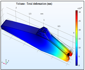
5.5.4 Arm resistance
The arm of the mechanism has an important role in the excavation operation. The arm is modeled with the following dimensions: length 1954.50 mm, width 152.37 mm, and height 316.33 mm. In order to properly test the strength of the arm, two different stresses were applied to the arm, 1.5 bars and 0.7 bars. As shown in Figure 12, two embedding have been applied to points A and B of the arm, and we have applied stresses to the borders of points C and D, (Figure 12a). With a stress of 1.5 bars, we obtained a bending deformation of 0.310-3 mm (Figure 12a), and a resistive Von Mises stress of 10.105 N/m2 (Figure 12b). Although, with a stress of 0,7 bars, we obtained a bending deformation of 0.1410-3 mm (Figure 12c) and a resistant Von Mises stress of 5.105 N/m2 (Figure 12d). From these results, we find that the arm of the modeled mechanism supports the stress exerted according to the nature of the Algerian soil.
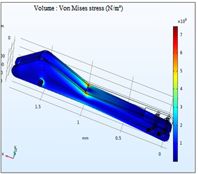
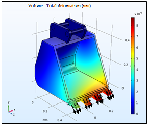
5.5.5 Bucket resistance
The bucket is the driving element in the excavation operation, since it is the only element of the mechanism that has direct contact with the ground. The bucket of the modeled mechanism has been designed with the following measurements: length 586.20 mm, width 503.79 mm, and height 514.84 mm. Figure 13 presents the bucket resistance of the modeled mechanism. As shown in Figure 13a, we have applied two embedding at points A and B of the bucket and we have applied two different values of stress on the borders at point C. With a Stress of 4.5 bars, we obtained a maximum bending deformation of 18.10-4 mm (Figure 13a), and a maximum resistant Von Mises stress of 10.1017 N/m2 (Figure 13b). While, for a stress tension of 2 bars, we obtained a bending deformation of 8.10-4 mm (Figure 13c) and a resisting Von Mises stress of 5.1017 N/m2 (Figure 13d).
The carried out work consists of the implementation of a system able to automatically excavating a parallelepiped-shaped pit, can be applied to the foundations of buildings or individual houses. The system has entered the foundation dimensions in 3D, and at the output an automatically excavated foundation. The objective is to calculate the positions of the different joints links between the different input-output parameters.
Through the study, we treated the concept of the mechanism simulation and its behavior with the ground, the manipulator arm of a backhoe was taken as a reference to model our mechanism with four degrees of freedom. The height of the mechanism cab is assumed to be 1 m above the ground level. The kinematic movement of the mechanism has been processed, in particular the relationship between the positions of the mechanism's joint links and the associated rotations angles, to test the responses of the modeled mechanism with the automation system; the desired shape and dimensions of the foundation. Two basic equations have been solved: rotation matrix and the transformation matrix of each link of the four components of the mechanism (cab-swing, boom, arm, and bucket).
In addition, the behavior of each component of the mechanism with the properties of the Algerian soil was studied, to test the resistance of the mechanism in terms of deformation and Von Mises stress.
As a perspective, we believe that there are still other functionalities to be added to the system such as the addition of the dynamic behavior of the mechanism with the consideration of all the forces that interact in the excavation operation.
[1] Koivo, A.J., Thoma, M., Kocaoglan, E., Andrade-Cetto, J. (1996). Modeling and control of excavator dynamics during digging operation. Journal of Aerospace Engineering, 9(1): 10-18.
[2] Gupta, M.K., Kumar, R., Verma, V., Sharma, A. (2021). Robust control based stability analysis and trajectory tracking of triple link robot manipulator. Journal Européen des Systèmes Automatisés, 54(4): 641-647. https://doi.org/10.18280/jesa.540414
[3] Singh, S. (1997). State of the art in automation of earthmoving. Journal of Aerospace Engineering, 10(4): 179-188. https://doi.org/10.1061/(ASCE)0893-1321(1997)10:4(179)
[4] Yoshida, T., Koizumi, T., Tsujiuchi, N., Jiang, Z., Nakamoto, Y. (2013). Dynamic analysis of an excavator during digging operation. SAE International Journal of Commercial Vehicles, 6: 419-428. https://doi.org/10.4271/2013-01-2410
[5] Tafazoli, S., Lawrence, P.D., Salcudean, S.E. (1999). Identification of inertial and friction parameters for excavator arms. IEEE Transactions on Robotics and Automation, 15(5): 966-971. https://doi.org/10.1109/70.795801
[6] Tafazoli, S., Salcudean, S.E., Hashtrudi-Zaad, K., Lawrence, P.D. (2002). Impedance control of a teleoperated excavator. IEEE Transactions on Control Systems Technology, 10(3): 355-367. https://doi.org/10.1109/87.998021
[7] Jie, L.W., Sen, T.P., Abdul-Ghani, N.M., Abas, M.F. (2021). Automatic control of color sorting and pick/place of a 6-DOF robot arm. Journal Européen des Systèmes Automatisés, 54(3): 435-443. https://doi.org/10.18280/jesa.540306
[8] Kim, D., Kim, J., Lee, K., Park, C., Song, J., Kang, D. (2009). Excavator tele-operation system using a human arm. Automation in Construction, 18(2): 173-182. https://doi.org/10.1016/j.autcon.2008.07.002
[9] Kim, J., Lee, S.S., Seo, J., Kamat, V.R. (2018). Modular data communication methods for a robotic excavator. Automation in Construction, 90: 166-177. https://doi.org/10.1016/j.autcon.2018.02.007
[10] Winck, R.C., Elton, M., Book, W.J. (2015). A practical interface for coordinated position control of an excavator arm. Automation in Construction, 51: 46-58. https://doi.org/10.1016/j.autcon.2014.12.012
[11] Liu, Y., Hasan, M.S., Yu, H.N. (2010). Modelling and remote control of an excavator. International Journal of Automation and Computing, 7(3): 349-358. https://doi.org/10.1007 /s11633-010-0514-8
[12] Gao, Y., Lou, W., Lu, H., Jia, Y. (2020). Consensus control of multi-agent robot system with state delay based on fractional order iterative learning control algorithm. Journal Européen des Systèmes Automatisés, 53(6): 771-779. https://doi.org/10.18280/jesa.530603
[13] Euldji, R., Batel, N., Rebhi, R., Lorenzini, G., Jarasthitikulchai, N., Menni, Y., Ahmad, H., Ameur, H., Sudsutad, W. (2022). Optimal design and performance comparison of a combined ANFIS-PID with back stepping technique, using various meta-heuristic algorithms to solve wheeled mobile robot trajectory tracking problem. Journal Européen des Systèmes Automatisés, 55(3): 281-298. https://doi.org/10.18280/jesa.550301
[14] Bradley, D.A., Seward, D.W., Mann, J.E., Goodwin, M.R. (1993). Artificial intelligence in the control and operation of construction plant—the autonomous robot excavator. Automation in Construction, 2(3): 217-228. https://doi.org/10.1016/0926-5805(93)90042-V
[15] Bradley, D.A., Seward, D.W. (1998). The development, control and operation of an autonomous robotic excavator. Journal of Intelligent and Robotic Systems, 21(1): 73-97. https://doi.org/10.1023/A:1007932011161
[16] Guan, D., Yang, N., Lai, J., Siu, M.F.F., Jing, X., Lau, C.K. (2021). Kinematic modeling and constraint analysis for robotic excavator operations in piling construction. Automation in Construction, 126: 103666. https://doi.org/10.1016/j.autcon.2021.103666
[17] Stentz, A., Bares, J., Singh, S., Rowe, P. (1999). A robotic excavator for autonomous truck loading. Autonomous Robots, 7(2): 175-186. https://doi.org/10.1023/A:1008914201877
[18] Khan, F.M., Islam, M.S., Hossain, M.Z. (2016). Design aspects of an excavator arm. International Review of Mechanical Engineering, 10(6): 437-442. https://doi.org/10.15866/ireme.v10i6.9395
[19] Kumar, B., Alam, T. (2016). Excavator bucket tooth wear analysis. In 2016 International Conference on Electrical, Electronics, and Optimization Techniques (ICEEOT), pp. 3364-3366. https://doi.org/10.1109/ICEEOT.2016.7755328
[20] Bošnjaka, S.M., Arsić, M.A., Gnjatović, N.B., Milenović, I.L.J., Arsić, D.M. (2018). Failure of the bucket wheel excavator buckets. Engineering Failure Analysis, 84: 247-261. https://doi.org/10.1016/j.engfailanal.2017.11.017
[21] Zhu, Q., Lu, P., Xiang, Q. (2020). Fatigue life evaluation of web butt welding structure on boom of excavator by hot spot stress approach. Engineering Failure Analysis, 113: 104547. https://doi.org/10.1016/j.engfailanal.2020.104547
[22] Solazzi, L. (2010). Design of aluminium boom and arm for an excavator. Journal of Terramechanics, 47(4): 201-207. https://doi.org/10.1016/j.jterra.2010.03.002
[23] Dhawale, R.M., Wagh, S.R. (2014). Finite element analysis of components of excavator arm-a review. International Journal of Mechanical Engineering and Robotics Research, 3(2): 340.
[24] Virág, Z., Szirbik, S. (2012). Examination of an optimized replaceable cutting tooth of excavator. Geosciences and Engineering, 1(1): 337-342.
[25] Xia, L., Quan, L., Ge, L., Hao, Y. (2018). Energy efficiency analysis of integrated drive and energy recuperation system for hydraulic excavator boom. Energy Conversion and Management, 156: 680-687. https://doi.org/10.1016/j.enconman.2017.11.074
[26] Liu, J., Jiao, Z., Xian, F., Liu, W. (2020). Energy recovery and utilization system of excavator boom based on flow regeneration and balance theory. Journal of the Brazilian Society of Mechanical Sciences and Engineering, 42(1): 1-11. https://doi.org/10.1007/s40430-019-2124-x
[27] Patel, B.P., Prajapati, J.M. (2011). Soil-tool interaction as a review for digging operation of mini hydraulic excavator. International Journal of Engineering Science and Technology, 3(2): 894-901.
[28] Coetzee, C.J., Basson, A.H., Vermeer, P.A. (2007). Discrete and continuum modelling of excavator bucket filling. Journal of Terramechanics, 44(2): 177-186. https://doi.org/10.1016/j.jterra.2006.07.001