Temitayo O. Ejidokun* | Olusegun O. Omitola | Azeez Fiyinfoluwa | Samuel Onodjohwo | Chigozie Odoguwu | Chidozie Odoguwu
© 2022 IIETA. This article is published by IIETA and is licensed under the CC BY 4.0 license (http://creativecommons.org/licenses/by/4.0/).
OPEN ACCESS
In the world today, fire incidence has been a frequent occurrence, this has caused the loss of many lives. Also, valuable properties, public utilities, and facilities have been destroyed. The study conceptualized a proposed design of an intelligent vision based robot for curbing the menace caused by fire outbreaks. The proposed design entails consistent remote interaction between a robot and sensor nodes. The robot node denotes the firefighting robot situated in the fire station. In its idle state, it operates in a passive node, by listening to the incoming beacons from the sensor nodes. The sensor nodes installed on designated sites consists of flame, wireless sensors with a mini-controller. Whenever the robot receives a distress alert from any of the sensor nodes, it automatically switches to an active mode and simultaneously navigates to the location in distress. The activity of the firefighting robot can be remotely monitored and controlled in real-time by a human operator via android-based application. However, modifications have been proposed, based on the identified flaws of existing systems. Successful implementation of this design will provide a reliable and efficient means of monitoring multiple sites in real-time and also ensure environmental safety.
robot, sensor node, SLAM, visual servoing, autonomous, navigation, obstacle avoidance, fire suppression
Fire has been known to mankind since the beginning of creation, which has greatly helped in his survival. Despite its usefulness, without its effective management and control, it can lead to devastating incidences and disasters. Statistics released by the fire service in Nigeria revealed that 262 lives were lost in 368 fire incidents in 2011, while 185 lives were lost in 470 fire incidence in 2012, properties valued at 5.95 billion naira were lost to the fire incident. In 2018, properties worth 3.3 trillion were lost to a fire outbreak in Kano alone and 3800 people were displaced [1]. In 2016, the World Life Expectancy reported highest number of death caused by fire incidents were recorded in Nigeria [2]. Also, the office of the Accountant-General of the Federation (AGF) and Corporate Affairs Commission (CAC) headquarters in Abuja were gutted by fire in April 2020. Many other cases have been reported [3]. Consequently, facilities of great worth such as offices, markets and other social amenities has been lost, also lot of people has been displaced and rendered homeless due to the occurrence of this devastating disaster. The reported outbreaks can be attributed to reoccurring power outage and surges resulting in electrical sparks, illegal connection of electricity, and the use of inappropriate electrical fittings. While other contributing factors include the indiscriminate keeping of fuel indoors, establishment of filling stations close to residential areas and market places. Furthermore, it has been discovered that the total neglect of fire safety measures during the design and construction of public and private buildings has immensely increased the occurrence of fire outbreaks in the country. Such safety measures include installation of fire extinguishers, fire and smoke detectors, the presence emergency exits and designated assemble fire points in building.
The job of carrying out rescue and extinguishing fire by firefighters is associated with several risks and life-threatening situations. It is a demanding job because it can take both a physical and mental toll on those who perform it. Firefighters are often exposed to burns, smoke inhalation and crush injuries from collapsing structures. Furthermore, they can suffer from heat exhaustion and also long-term job-related illnesses such as asthma, persistent coughing, heart disease, and cancer as well as lung damage. The National Fire Protection Association in the US reported 29,130 injuries and 68 on-duty death of personnel fighting fire in 2015 [4]. The recorded statistics of Injuries and casualties incurred during fire outbreaks are alarming, this has prompted concerted efforts among governmental bodies and private tech companies in looking into innovative means of curbing the menace of fire.
Firefighting robots are designed to monitor environmental variables to detect fire in order to control and suppress it, thereby preventing further damage. Fixed firefighting robotic systems, like automatic fire sprinklers and alarms, are used in heavily populated and hazardous areas for rapidly extinguishing any threat. In a smart city/internet of things (IoT) ecosystem, information and communication technologies (ICT) are employed through the use of diverse electronic sensors to collect and deliver information with aid of web-enabled devices. This will help to manage possessions, resources and enhance effective delivery of urban services that will eventually wastage and incurred costs. Its main goal is to simplify the lifestyle of household users, create a safe and conducive living/working environment through the automation of household tasks and processes. Hence, the use of information and communication technology helps in managing time and resources effectively [5]. In the course of suppressing fires, incorporating smartness into a fighter fighting robot, time is extremely essential. Therefore, incorporating smartness using IOT-based technology will aid its prompt response to critical urgency. This will prevent damage to properties and save lives.
Several scholars have developed various systems to curb the menace caused by fire outbreaks. Rakib & Sarkar [6] presented an autonomous robot that can detect fire using three sensors; temperature, flame and smoke sensor and automate the sprinkler nozzle wherever fire has been detected. The sensitivity of the sensors was tested at different times of the day. The results show that the robot can effectively detect and extinguish small scale fire. A robot that can work using communication links such as DTMF, Bluetooth, and GSM to promptly respond to threatening fire incidence was designed in Rashid et al. [7]. Three sensors: temperature, flame, and smoke sensors were used for the effective detection of fire. The result obtained from its performance analysis demonstrated that it can effectively extinguish the fire. A firefighting robot; a ceasefire designed to extinguish a fire using a spray that contains water and carbon dioxide was presented in Mittal et al. [8]. It is equipped with a camera for remote monitoring and also a self-protect mechanism that will prevent the destruction of the system by fire. The identified merits of the system are; its ability to swiftly respond to a distress call and long-range controllability by an operator. The result obtained from its testing proved that this system is fast, reliable, and efficient. Aliff et al. [9] presented QROB, a firefighting robot programmed to locate a burning fire at a maximum distance of 40cm. Also, a camera was integrated, to enable the operator to monitor the situation remotely via a smartphone. The outcome of the field test carried out shows that the QROB can effectively detect and suppress the fire.
The authors [10] worked on a mobile robot that can detect fire indoors with a special capability of assessing elevated buildings by climbing stairways to locate the fire. Furthermore, multiple insulation materials were incorporated into the robot so that it can withstand a temperature of about 700 degrees Celsius for 60 minutes. It has audio and video capability which is useful for remote visualization and communication with trapped victims. An autonomous firefighting robot implemented in Hassanein et al. [11] employed a combination of infrared and ultrasonic sensors for navigation. Also, a live feed from a camera mounted on the robot for monitoring and a map representation provided a means of localizing the robot in case of any eventuality. Furthermore, flame sensors were used to detect fire, while a fan was used to extinguish the fire. The robot was tested by setting up fire at four-point within the transverse arena and assigned the task of putting out the fire repeatedly, the outcome demonstrates that the task was performed successfully with high precision and accuracy within a short time. An IOT-based robot model developed by Kanwar & Agilandeeswari [12] can detect fire and respond to its distress call promptly. Furthermore, it can classify the type of fire based on the amount of carbon monoxide produced, to apply the appropriate agent to extinguish the fire which can be either water or carbon dioxide. This helps to avert the re-igniting of fire through the application of the wrong agent. The authors [13] developed a vision-based algorithm for on-site detection of fire and a mechanism for an autonomous response towards the point of detection. An intelligent vision-based robot that can detect and classify fire using a convolutional neural network technique implemented on a raspberry pi was presented in Dhiman et al. [14]. The obstacle avoidance was designed with an ultrasonic sensor, while remote communication was handled by a GSM module [15].
In most of the reviewed works discussed above, ultrasonic sensor was used for obstacle detection and avoidance. Despite the obvious advantages of the sensor, it has some peculiar limitations that has been identified. Such that if the detected obstacle is positioned, the signal is deflected rather than reflecting back to ultrasonic sensor. The will leads to incorrect estimation of its distance to the object. Furthermore, its signals tend to get distorted by some materials. Also, the sensor tends to detects false signals produced by disturbed airwaves, resulting in inconsistency and inaccurate distance measurement, thus making it unsuitable enough for detection of obstacles [16].
In addition, it was observed that the existing systems lack appropriate intelligent vision-based system that can adequately map the site of the fire and carry out an organized task of suppressing the fire. The identified limitation tends to compromise the accuracy and precision of the robot in executing the task. In a bid to improve the navigation capability, accuracy, precision, speed of the on-site suppression of fire by existing robotic design. This study seeks to propose an integrated design of an IOT based firefighting station.
The major focus of the conceptual design is as follows; proposal of a robust activity cycle for an IOT Based fire station. The integration of light detection and ranging (LiDAR) sensor and the implementation of simultaneous location and mapping (SLAM) technique to enhance the navigation capability of the firefighting robot. The use of a position-based visual Servoing technique to accurately map out the isolated portion of the fire to be extinguished one at a time and precisely direct the sprinkler to the exact point of position estimation.
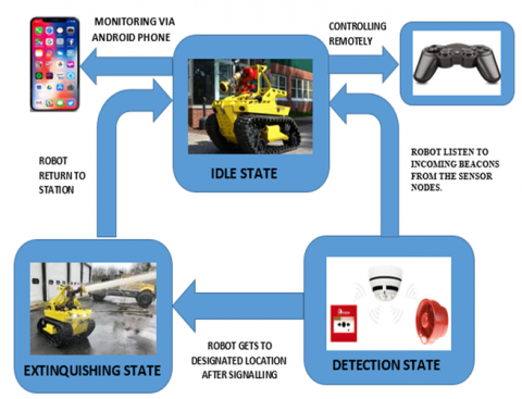
Figure 1 shows the firefighting activity cycle of the proposed robot, named Ronabot. This depicts the process that has to take place to initiate effective monitoring, detection, response and rescue of the fire incident situation.
Figure 1. Activity cycle of the Ronabot
The cycle is composed of three states; idle, detection and extinguishing state. During the idle state, the robot is stationary at the fire station operating in a passive mode; it receives beacons from flame sensor nodes, positioned at various points to be monitored in real-time at both long and short-range.
The detection state entails the reception and response to the distress call from any of the monitored points which trigger an alarm. Ronabot with the aid of maps and inbuilt GPRS locates and navigate to the site of the incident, which can be either autonomous or remotely controlled by an operator. The task of putting out the fire takes place at the extinguishing state. The robotic vehicle is equipped with various cameras, sensors and actuators to monitor and record the activity remotely; sensors to detect the fire points, and also monitor the health status of the robots; valves and pumps direct water to the specified points to extinguish the fire.
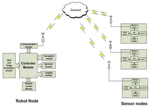
The entire Ronabot system is made up of a robot and sensor node as well as several modules. The controller module and communication module are embedded within the robot node. The sensor node, on the other hand, consists of several modules such as detection and monitoring, controller navigation, communication, logging module as shown in Figure 2.
Figure 2. Block diagram of the IOT-based fire-fighting robot
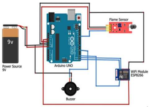
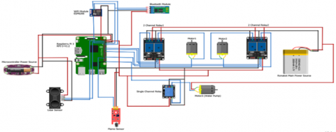
The circuit of the robot and sensor node is presented in Figure 3 and Figure 4 respectively. The data acquisition module contains the IP camera, thermal cameras, temperature, flame, and smoke sensors and alarm function integrated into it.
The IP camera was used for on-site real-time video monitoring. It is 1080 pixels (1920*1080) internet protocol type of digital camera that receives control data and sends the live image data via the internet to the operator’s android phone detect light in the range of 760nm-1100nm wavelength, with a detection distance of 100cm. Raspberry Pi B+ revision 4 is the major component to be employed for the controller module. It consists of an ARM1176JZF-S processor, which runs at 700 MHz clock speed, a Video Core (IV) graphic processor unit (GPU), 512 MB SDRAM shared with GPU, 2 Universal Serial Bus (USB) port, 1 video and audio output, 1 100 Mbit/s Ethernet port, 1 high-definition multimedia interface (HDMI) output. It also has 26 pins, including 8 general purpose Input/output (GPIO), 1 I2C bus, 1 SPI bus, 1 UART bus and 3.3V, 5V, and ground (GND). Raspberry Pi does not have an onboard chip memory. It uses an external secure digital (SD) card to run its operating system and store its user data. Raspberry Pi can be accessed either by connecting keyboard, mouse, and monitor to it or connecting it to a local network to remotely access via a secure shell (SSH) terminal.
LM35 is to be used for temperature detection and monitoring of the robot so that it does not get too close to the fire. It was chosen because of its ability to accurately detect an abrupt rise in temperature with less heating effect. It is capable of operating within a voltage range of 4v-30v with a drain current of less than 60µA. The Arduino flame sensor can detect light in the range of 760nm-1100nm wavelength, with a detection distance of 100cm.
Figure 3. Circuit diagram of the sensor node
Figure 4. Circuit diagram of the robot node
The main component considered appropriate for the sensor node shown in Figure 3, is the Arduino Mega 2560 microcontroller. The function of the module is to accept data from the flame sensors, interpret and send it to the robot node. It consists of 54 digital input/output pins (of which can be used as PWM outputs), 16 analog inputs, 4 UARTs (hardware serial ports), a 16MHz crystal oscillator, a USB connection, a power jack, an ICSP header, and a reset button. It operates at 5V, possesses a flash memory of 256 KB (of which 8 KB is used by the bootloader), SRAM of 8 KB, and EEPROM of 4 KB. The communication module is made up of the Bluetooth and Wi-Fi transceivers interfaced with the Arduino MEGA to allow serial communication between the model and the sink nodes, to enable it accept control command. The ESPN 8266 operates at a clock speed of 80 MHz, voltage of 3.3v, flash memory 4MB, SRAM of 64 KB. It is most preferred because it has a robust on-board processing and storage capability. The HC 06 Bluetooth uses a low-power radio waves on a frequency band between 2.402 GHz and 2.480 GHz to establish communication between a transmitter and receiver using the master –slave switch configuration, with a data rate of 2.1mb.
The logging module will be used to keep track of the activity of the robot, monitor the health status of the robot via an android based mobile phone. The status to be monitored include the battery level, water level, temperature of the robot and also the current robot’s location. The sprinkler modules consist of the water tank, pump and sprinkler value. The navigation module is driven by two differential wheels mounted on a common axis controlled by two separate motors at the rear end of the chassis, supported by a caster wheel at the front end.
3.1 Motor driver design
The conventional motors driver integrated circuit is unsuitable for driving the motor with required efficiency, due to the high current requirement of the motor. This problem can be resolved by designing a robust motor driver with four relays as shown in Figure 5. It consists of two motors (Motor 1 & Motor 2) and four relays (Relay 1, Relay 2, Relay 3 & Relay 4) setup. The operation of the relays is given such that, whenever, the four relays are put in the Normally Open (NO) or left in the Normally Closed (NC) position simultaneously, neither of the motors will rotate, causing the robot to halt.
Figure 5. Circuit diagram of the relay configuration for driving the wheel
Table 1. Relay configuration for the motor with respect to motor
|
Direction |
Relay 1 |
Relay 2 |
Relay 3 |
Relay 4 |
|
Forward |
1 |
0 |
1 |
0 |
|
Backward |
0 |
1 |
0 |
1 |
|
Left |
1 |
0 |
0 |
1 |
|
Right |
0 |
1 |
1 |
0 |
When Relay 1 & Relay 3 are on the Normally Closed (NO) position while Relay 2 & Relay 4 are left in the Normally Closed (NC) position simultaneously, Motor 1 and Motor 2 will rotate in the clockwise direction, causing the robot to move forward as illustrated in Table 1. Moreover, if Relay 1 & Relay 3 are left in the Normally Closed (NC) position while Relay 2 & Relay 4 are put in the Normally Closed (NO) position simultaneously, both Motor 1 & Motor 2 rotates in the counterclockwise direction, causing the robot to move backwards.
Also, if Relay 1 & Relay 4 are in the Normally Closed (NO) position while Relay 2 & Relay 3 are left in the Normally Closed (NC) position simultaneously, Motor 1 rotates in the clockwise direction while Motor 2 rotates in the counter-clockwise direction, causing the robot to move left. Lastly, when Relay 2 & Relay 3 are put in the Normally Closed (NO) position while Relay 1 & Relay 4 are left in the Normally Closed (NC) position simultaneously, Motor 1 rotates in the counter-clockwise direction while Motor 2 rotates in the clockwise direction, causing the robot to move right.
3.2 Motor sizing calculation
A preliminary calculation was carried out to ascertain the torque, velocity and power required to move the Ronabot and recommend the appropriate motor specification using Eqns. (1)-(7). Given:
Total weight of the robot (w) =50kg
Nominal velocity of the robot (v) = 0.8m/s
Radius of the wheel (r) = 0.1 m
Maximum inclination ($\theta$) = 8 degrees
Acceleration due to gravity (g) =9.81m/s2
The co-efficient of static friction (µ) = 0.5.
$\sum F_{\text {orce }}=F_{\text {total }}=F_{w}-F_{g}-\mu N=m a$ (1)
$\mathrm{F}_{\mathrm{W}}=$ The force pushing againt the wheel
$\mathrm{F}_{\mathrm{g}}=$ Torce pulling the robot down due to gravity
$\mathrm{F}_{\mathrm{r}}=$ Frictional force
$M_{t}=$ Total mass of the robot
$\mathrm{a}=$ Acceleration
$\mathrm{F}_{w}=m a+F_{g}+\mu N$
$F_{g}=m g \sin \theta$ (2)
$N=M g$ (3)
Since $T_{L}=F_{w} * r$ (4)
where;
$\mathrm{T}_{\mathrm{L}}=$ Load Torque
$\mathrm{r}=$ radius of thewheel
$T_{L}=(m a+m g \sin \theta+\mu N) * r$
$\mathrm{~T}_{\mathrm{L}}=50\left(0.3+9.81 \sin 8+0.5^{*} 9.81\right)^{*} 0.1$
$\mathrm{~T}_{\mathrm{L}}=37 \mathrm{Nm}$ (5)
since we are using Two (2), the required torque per motor will be; $=\frac{37 \mathrm{Nm}}{2}=18.5 \mathrm{Nm}$. Also the required wheel rotation speed $\left(\mathrm{N}_{\mathrm{T}}\right)$ is estimated in Eqns. (4)-(6).
$\begin{aligned} N_{T} &=\frac{60 * V}{\pi^{*} D_{W}} \\ \mathrm{~N}_{\mathrm{T}} &=\frac{60 * 0.8}{3.142^{*} 0.2} \\ \mathrm{~N}_{\mathrm{T}} &=76.5 \mathrm{RPM} \end{aligned}$ (6)
The require power $(\mathrm{P})$ for the motor is given by :
$\begin{aligned} P &=F_{w} * V \\ &=370^{*} 0.8 \\ &=276 \mathrm{~W} \end{aligned}$ (7)
Based on the exact motor sizing calculation, using Eqns. (1)-(7), two (2) high torque brushless hub DC motor with relatively low power of 350w, a wheel rotation speed of 180 revolutions per minute and a torque of 20-25 Nm is recommended for this design.
3.3 Obstacle detection and navigation
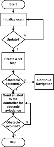
The LiDAR sensor will be used to detect and avoid obstacles, for the robot to reach its destination without any disturbance. LiDAR is considered appropriate for this design due to its high degree of accuracy in carrying out measurements and detecting obstacle [16-18]. The sensor fires rapid pulses of laser light at a surface, at 150,000 pulses per second. It estimates the time it takes to receive the pulse based on that time. The distance of the obstacle from the robot is computed using Eq. (8):
$D_{S}=\frac{v t}{2}$ (8)
where, Ds=estimated distance between Ronab and the obstacle; v=velocity of sound in air=340 m/s=0.034cm/s; t=time of flight.
The motion control decision is based on Eq. (9):
$D_{u}=\left\{\begin{array}{l}1, D_{s} \leq D_{\text {safe }} \\ \frac{D_{\text {safe }}}{D_{s}}, D_{s} \geq D_{\text {safe }}\end{array}\right.$ (9)
where, Du=distance value of the LIDAR sensor; Ds=current distance between the robot and the sensor, Dsafe=present threshold distance at which obstacle is to be detected.
Whenever there is no obstacle detected by the sensor, it records a value of 1, also if the sensor senses an obstacle it implies that Ds is greater than Dsafe and therefore, it records a value less than 1. The sensor sends the message to the microcontroller, to institute an action to control the motion of the robot to avoid the obstacle. Figure 6 shows the proposed flowchart for the SLAM algorithm that will be used for obstacle avoidance. With the aid of the LiDAR sensor, the robot builds a glob map for its environment. It uses the map to navigate and deduce its location.
Figure 6. Proposed flowchart diagram for SLAM algorithm
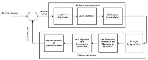
Figure 7. Position-based visual servoing mechanism
3.4 Image visual servoing mechanism
The proposed design in Figure 7 is a position-based visual servoing mechanism, which will be incorporated into the sprinkler module. This mechanism will ensure that the fire is located, in order to accurately and precisely point the nozzle burning point detected. Feature extraction takes place through image acquisition and extraction of required information which will aid position estimation. The data obtained will be used to decide the exact behavioural response suitable for the task and also estimate the time taken to achieve the aforementioned. The actual feature and desired feature extracted is essential for robotic motion control to take an appropriate decision to execute the designated task by the position-based servo control and joint controller. The position-based visual servoing controller will be implemented using the eye to hand paradigm to coordinate motion on the mapped area to allow continuous incremental visual feedback and corrections [19, 20]. The function of the joint controller is to provide to the endpoint of the robot, the desired pose for the task.
3.5 Software implementation
The software program that runs in the controller module will be implemented in C++ language and compiled using Arduino IDE. The language is the most preferred due to its high execution speed and flexibility in providing low-level access to the hardware memory. The android based monitoring and logging system to be deployed on a mobile phone will be designed using MIT app inventor. It is a free and open-source software-based web application for Android Operating Systems (OS).
Figure 8. Proposed flowchart diagram of the robot’s operation
Figure 8 shows the proposed flowchart of the Ronabot model. In the incident of a fire at a certain location, the sensor node at that location detects the fire and sends an alert to the pre-installed Ronabot app on the operator’s android phone and the Ronabot. The Ronabot responds to this alert either by manual or automatic initialization, the IP camera feed becomes active to be remotely monitored by an operator. Based on the broadcasted location of the sensor node, it creates a path and map, then navigates to the exact location. Whenever the robot encounters an obstacle, it avoids it and continues on its path. On reaching the location of the fire, it stops, uses its onboard visual servoing mechanism to scan and assess the site. It then automatically activates the sprinkler and administer it from point to point until the fire has been suppressed. Once this task has been accomplished, the Robot stops spraying and return to the station.
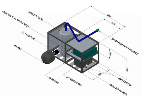
3.6 Computer aided design of the robotic chassis
Figure 9 shows a draft of the design of the robotic chassis developed in the AutoCAD Plant 3D environment. The construction of this framework will be done using the following materials that are locally sourced; sheets of mild steel. ¾ angle Iron, 1-meter-long electrode, cutting disc, grounding disc. The sheet of mild steel will be used for the base and walls of the frame while the angle iron will support the frame. The electrode, cutting disc, and grounding disc will be used to aid the entire construction process of the framework. The chassis was divided into two parts vertically; the first part location is provided to accommodate the water tank and the rear wheel. The second compartment was further divided into two parts, upper and lower deck. The lower deck contains the batteries while the upper deck was used to accommodate the controller and other components.
Figure 9. AutoCAD design of Ronabot’s framework
The study has proposed a robust design of an IOT-based robot that can effectively suppress and eventually extinguish fire. This was with a view of suggesting modalities for improving navigation capability, accuracy, precision and speed in suppressing fire outbreak based on the identified flaws of existing designs. An activity cycle, outlining the sequential process of executing the task of attending to fire incidence was presented. Furthermore, the use of LiDAR sensor in conjunction with SLAM algorithm for detection and avoidance of obstacle during navigation was proposed. Also, the study recommended the integration of position-based servoing into the sprinkler module to accurately map isolated portion of the fire to be suppressed and precisely position the nozzle to effectively handle the task.
This conceptualized design is well suited for smart urban environment, as this will provide a platform for remotely monitoring the designated areas in case of unforeseen fire incidence, receiving alerts and promptly responding to the distress call. In further works, the proposed design will be implemented and its performance will be evaluated, in order to ascertain its strength and weakness.
[1] Umanah I.I, Adekunle A., Ibe, K.E., Rukewe, I.M. (2018). Statistical analysis of fire outbreaks in homes and public buildings in Nigeria: A case study of Lagos state. International Journal of Engineering and Advanced Technology, 4(8): 21-30.
[2] Eugene E. (2019). Nigeria: Deadly fire outbreaks - attitudes must change, daily trust newspaper. Available online at https://dailytrust.com/deadly-fire-outbreaks-attitudes-must-change., accessed on 16 July 2020.
[3] Okunola, H.O. (2020). Nigeria: Curtailing fire outbreaks in Nigeria, this day newspaper. Available online at https://www.thisdaylive.com/index.php/2020/07/13/curtailing-fire-outbreaks-in-nigeria/, accessed on 17th August 2020.
[4] Eastern Kentucky University. (2019). The use of robotics in Firefighting. https://safetymanagement.eku.edu/blog/the-use-of-robotics-in-firefighting/, accessed on 7th August 2020.
[5] Ilayarani, P.P., Dominic, M.M. (2019). Smart firefighting system for smart cities adopting fog/edge computing. International Journal of Innovative Technology and Exploring Engineering (IJITEE), 8(10): 3930-3936.
[6] Rakib, T., Sarkar, M.R. (2016). Design and fabrication of an autonomous fire fighting robot with multisensor fire detection using PID controller. In 2016 5th International Conference on Informatics, Electronics and Vision (ICIEV), pp. 909-914. https://doi.org/10.1109/ICIEV.2016.7760132
[7] Rashid, H., Ahmed, I.U., Ullah, A., Newaz, M.F., Robin, M.S.R., Reza, S.T. (2016). Multiple sensors based fire extinguisher robot based on DTMF, Bluetooth and GSM technology with multiple mode of operation. In 2016 International Workshop on Computational Intelligence (IWCI), pp. 41-46. https://doi.org/10.1109/IWCI.2016.7860336
[8] Mittal, S., Rana, M.K., Bhardwaj, M., Mataray, M., Mittal, S. (2018). CeaseFire: The fire fighting robot. In 2018 International Conference on Advances in Computing, Communication Control and Networking (ICACCCN), pp. 1143-1146. https://doi.org/10.1109/ICACCCN.2018.8748547
[9] Aliff, M., Yusof, M., Sani, N.S., Zainal, A. (2019). Development of fire fighting robot (QROB). Development, 10(1). https://doi.org/10.14569/IJACSA.2019.0100118
[10] AlHaza, T., Alsadoon, A., Alhusinan, Z., Jarwali, M., Alsaif, K. (2015). New concept for indoor fire fighting robot. Procedia-Social and Behavioral Sciences, 195: 2343-2352. https://doi.org/10.1016/ jsbspro.2015.06.191
[11] Hassanein, A., Elhawary, M., Jaber, N., El-abd, M. (2015). An autononous figher fighting robot. International Conference on Advanced Robotics (ICAR), pp. 530-535. https://doi.org/10.1109/ICAR.2015.7251507
[12] Kanwar, M., Agilandeeswari, L. (2018). IOT based fire fighting robot. In 2018 7th International Conference on Reliability, Infocom Technologies and Optimization (Trends and Future Directions)(ICRITO), pp. 718-723. https://doi.org/10.1109/ICRITO.2018.87 48619
[13] Rangan, M.K., Rakesh, S.M., Sandeep, G.S.P., Suttur, C.S. (2013). A computer vision based approach for detection of fire and direction control for enhanced operation of fire fighting robot. In 2013 International Conference on Control, Automation, Robotics and Embedded Systems (CARE), pp. 1-6. https://doi.org/10.1109/CARE.2013.6733740
[14] Dhiman, A., Shah, N., Adhikari, P., Kumbhar, S., Dhanjal, I., Mehendale, N. (2020). Fire Fighter Robot with Deep Learning and Machine Vision. https://dx.doi.org/10.2139/ssrn.3633609
[15] Zhu, J., Li, W., Lin, D., Cheng, H., Zhao, G. (2020). Intelligent fire monitor for fire robot based on infrared image feedback control. Fire Technology, 56(5): 2089-2109. https://doi.org/10.1007/s10694-020-00964-4
[16] Pandey, M., Mishra, G. (2019). Types of sensor and their applications, advantages, and disadvantages. In Emerging Technologies in Data Mining and Information Security, Springer, Singapore, pp. 791-804. https://doi.org/10.1007/978-981-13-1501-5_69
[17] Predota, J. (2016). LiDAR based obstacle detection and collision avoidance n an outdoor environment, Published Bachelor’s. Thesis, Department of Control Engineering, Czech.
[18] Kim, P., Chen, J., Kim, J., Cho, Y.K. (2018). SLAM-driven intelligent autonomous mobile robot navigation for construction applications. In Workshop of the European Group for Intelligent Computing in Engineering, Springer, pp. 254-269. https://doi.org/10.1007/978-3-319-91635-4_14
[19] Naminski, M.R. (2013). An analysis of simultaneous localization and mapping (SLAM) algorithms. Mathematics, Statistics and Computer Science Honors Projects.
[20] Berrabah, S.A., Baudoin, Y., Sahli, H. (2010). SLAM for robotic assistance to fire-fighting services. In 2010 8th World Congress on Intelligent Control and Automation, pp. 362-367. https://doi.org/10.1109/WCICA.2010.5554978