Bangarraju Jampana* | Jayalaxmi Askani | Rajagopal Veramalla
© 2022 IIETA. This article is published by IIETA and is licensed under the CC BY 4.0 license (http://creativecommons.org/licenses/by/4.0/).
OPEN ACCESS
This work presents a way to handle the DC component of input signals for PLL and notch filter applications, which are utilized for filtering and synchronization. The input signal of a DC component may be due to some sort of malfunction, or it may be the result of the structure and restrictions of the measurement/conversion procedures. This part makes the system's loop oscillate at low frequencies and no filter can fully filter them out because that would significantly harm the system's dynamic response. The proposal involves augmenting the PLL structure with a new loop. It is basic architecturally and in contrast to a currently presented method and it does not detract from the algorithm's high-frequency filtering level. This Orthogonal Signal Generators (OSG) control algorithm is used for active power filter to maintain unity power factor, neutral current compensation using star/three single transformer & current harmonics mitigation. The MATLAB/Simulink results are demonstrated for the above stated Power Quality (PQ) problems.
active power filter, neutral current compensation, notch filter, power quality, harmonics
One of the most essential issues in the present distribution system is compensating of reactive power from non-linear and/or inadequate power factor loads. The problem is exacerbated by unbalanced loads. Any reactive power demand that is too high will make the feeder losses and active power flow capacity of the distribution system suffer, while causing transformer and generator damage due to a lack of balance [1]. Various load compensation solutions have been presented during the past two decades. Unbalanced and distorted currents can be corrected with these methods as can the power factor at the load bus [2]. It's important to note that all of these systems are predicated on the assumption. As a result of this, it is possible that the upstream source voltages are imbalanced or in such instances, sensitive loads must be safeguarded by a compensator that can modulate the bus voltage to give a balanced sinusoidal voltage of a predetermined magnitude [3]. Active Power Filters are widely utilized in the distribution system for reactive power compensation, load balancing, and harmonic mitigation.
There are APFs that can be used to compensate nonlinear loads for harmonic currents [4]. In either case, they can be coupled, either as a harmonic solution next to a nonlinear load or as a global solution at the Point of Common Coupling (PCC). It is typically determined by the performance, stability of network, and mitigation harmonic efficiency sought and also taken into account for cost.
As soon as the APF detects the harmonic spectrum of the load current, it generates an output current with a similar harmonic spectrum to that of the load current.
The APF does this, so the power system can concentrate on providing a fundamental current component [5]. Advancements in various control devices and algorithms make this possible. In addition to laboratory testing, these factors allowed APFs to be applied to real-life situations. An APF is more efficient than a shunt passive filter because the real power consumption is lower. Unlike shunt passive filters, there is no need to connect multiple branches to mitigate multiple harmonic orders at once [6].
One APF can shield upto a 30th–50th order harmonic, satisfying actual regulatory standards [7]. However, even if voltage imbalances and pre-distortions are avoided, APFs can still maintain the same high-quality harmonic current. The Total Harmonic Distortion (THDi) is estimated to be 5-7% with an APF and 10-15% with a passive filter. It is also more expensive (in terms of equipment, installation and maintenance) than traditional passive filters [8, 9].
An APF can be improved without changing its design by adding more power-quality features such as compensating for voltage imbalance, dips, surges, flickers and dampening circuit resonances [10, 11]. Even though the foregoing considerations raise the cost of harmonic mitigation, the additional energy requirements of the APF's inverter can be carried. DC-link and power inverter capabilities will be improved with a larger energy storage DC-link as well as an increase in the IGBT, boost filter size, heat-sink and ventilation [12-14].
Power systems use the SRF-PLL, commonly known as the dqo-PLL. When the input signal is imbalanced, the SRF-PLL suffers from double-frequency inaccuracy [15]. As a result, A Low-Pass Filter (LPF) can be used to reduce or eliminate the error whereas dual structures for negative and zero components can be used to eliminate the error [16-18].
A building block for OSG has been created with the usage of the Second-Order Generalised Integrator (SOGI) [19]. In addition to using a DQ system, you can use an orthogonal signal in a frequency locked loop (FLL) to estimate frequency [20, 21]. This approach aligns with the idea of an adjustable notch filter (ANF) [22]. These tools have applications in control, filtering and frequency These tools are useful for frequency estimates, control, filtering, harmonics estimation, grid synchronization, as well as for three-phase applications [23, 24]. The frequency predicted by these approaches is inaccurate when the input signal has some DC [25].
This study proposes and studies an OSG control algorithm based APF for mitigating harmonics and unity power factor maintenance. For neutral current compensation is achieved by connecting star/three I-Ø transformers [26]. The proposed 6-leg VSC based Active Power Filter model is developed by using MATLAB/SIMULINK.
Line diagram of Active Power Filter system with inductive load attached to distribution lines is shown in Figure 1. To keep the link voltage constant, a capacitor is attached to the input of the VSC. To maintain dc bus voltage and voltage regulation, Cdc generators and PI controllers are used, which in conjunction with the PWM Current Controller give switching signals for the VSC. There is a switch that allows you to regulate source currents so that at the load end, an ac capacitor bank is connected to lower the rating of Active Power Filter.
The DC capacitor, ripple filter, and IGBTs were selected according to the design of an APF. The line voltage of 415V is at the source, and the capacitor voltage is considered to be 700V. The choice of 3,000µF capacitor is considered as DC bus capacitor. The voltage of a DC capacitor is ascertained with the assistance of a star/three I-Ø transformer. The neutral is balanced by the use of a star/three I-Ø transformers to minimise the DC link voltage of the voltage source converter.
The in-phase unit templates xpa, xpb and xpc are
$x_{a p}=v_{s a} / v_{s t} ; x_{b p}=v_{s b} / v_{s t} ; x_{c p}=v_{s c} / v_{s t}$; (1)
Then the terminal source current (vst) is calculated as follows:
$v_{s t}=\sqrt{\frac{2}{3}}\left(v_{s a}^{2}+v_{s b}^{2}+v_{s c}^{2}\right)^{0.5}$ (2)
To measure the voltage error, subtract Vdc from the reference dc connection voltage Vdc* as follows:
$V_{d r e}=-V_{d c}(m)+V_{d c}^{*}(m)$ (3)
Kpd is a proportional gain and Kid is an integral gain, which is used to determine the dc loss component, Ilss.
$I_{l s s}(m)=I_{l s s}(m-1)+K_{p d}\left\{V_{d r e}(m)\right\}$$+K_{i d}\left\{V_{d r e}(m)-V_{d r e}(m-1)\right\}$ (4)
A method for rejecting quadrature signal DC offset is presented in Figure 1. To remove the input signal from the integrator, it adds the third state variable, x0, with the second state variable, x1.
Figure 1. APF power circuit configuration and control algorithm
To reject the quadrature signal's DC off-set, the method proposed in Figure 1 has been developed. To subtract the input signal from the integrator, it adds the third state variable, x0, with the second state variable, x1. Transfer functions for this system include:
$T F=\frac{X_{1}(s)}{V(s)}=\frac{w_{o} s^{2} k}{\Delta(s)}$; (5)
$\frac{X_{2}(s)}{V(s)}=\frac{w_{o} s^{2} k}{\Delta(s)}$; (6)
$\frac{X_{o}(s)}{V(s)}=\frac{w_{o}\left(s^{2}+w_{o}^{2}\right) k_{o}}{\Delta(s)}$; (7)
where, $\Delta(s)=s^{3}+\left(k_{o}+k\right) w_{o} s^{2}+w_{o}{ }^{2} s+k_{o} w_{o}{ }^{3}$ where $\Delta\left(j w_{o}\right)=-k_{o} w_{o}^{3}$ as a result, it is determined that x1 is a filtered band pass variation of the input signal that does not have a phase shift, whereas x2 is a filtered band pass variation of the input signal that has a 90° phase shift and x0 will be a low-pass/notch-filtered variation of the input signal. So, as far as dc offset is concerned, x1 and x2 have none and x0 is equal to the dc input signal.
An improved single-phase PLL with dq-based single-phase OSG, shown in Figure 1, can be employed to correct this problem.
It is possible to extract the fundamental power component of phase ‘a’ source current from Figure 1 and similarly for phase ‘b’ and source phase ‘c’ components are extracted.
The average value of current is estimated as:
$I_{d a v g}=\left(I_{d s a}+I_{d s b}+I_{d s c}\right) / 3$ (8)
The average values of individual phase components is added to loss component of current.
$I_{d}=I_{d a v g}+I_{l s s}$ (9)
Active power filter reference source currents are estimated as:
$i_{s a}^{*}=x_{a p} I_{d} ; i_{s b}^{*}=x_{b p} I_{d} ; i_{s c}^{*}=x_{c p} I_{d}$; (10)
In order to measure the error currents for the 6-leg VSC, reference currents are compared with the estimated currents. This type of gate generation uses a triangle wave signal to create unipolar pulses.
iea>itr (left leg phase 'a' upper switching device is activated);
iea< itr (left leg phase 'a' lower switching device is activated);
-iea>itr (right leg phase 'a' upper switching device is activated);
-iea≤itr(right leg phase 'a' lower switching device is activated).
In a similar manner, the other two H-bridge VSCs in the last phase of the system change their operating mode when the PWM switching frequency is doubled and the filter requirement is reduced.
The DC and AC PI controller gains constants obtained using the Ziegler–Nichols step response technique. A step input of amplitude (U) is applied and the output response of the dc bus voltage is obtained for the open-loop system. The maximum gradient (G) and the point at which the line of maximum gradient crosses the time axis (T) are computed. The gains of the controller are computed using the following equations:
$K_{p}=|1.2 U / G T|$ (11)
$K_{p}=\left|0.6 U / G T^{2}\right|$ (12)
The gain values for both the DC and AC PI controllers are computed and are given in the Appendix.
These Figures 2 and 3 show the performance of OSG control algorithm for Active Power Filter (APF) with six legs. In addition to power factor correction, harmonic suppression and neutral current compensation, the MATLAB simulation results of the proposed APF are shown.
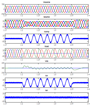
A 6-leg VSC-based Active Power Filter with linear loads performance parameters are depicted in Figure 2. In Figure 2, variations in the source voltages (vsource), source currents (Isource), compensator currents (Icomp), load currents (Iload), dc bus voltage (vdc), compensator neutral current (Icn) and source neutral current (Isn) between t=1.15 sec to 1.4 sec are observed. To begin with, one phase of the load is detached for 1.2 sec before reapplying it for 1.35 sec. Source voltages (vsource) and source currents (Isource) are reported to have the same power factor under a variety of load circumstances. harmonic-free and balanced changes in the source voltages (vsource) and source currents (Isource) are observed. Active Power Filter using star/three I-Ø transformers compensate the unbalanced load neutral current, while the source neutral current (Isn) is zero. As a result of this, the DC bus voltage (vdc) is kept constant at 400V.
A 6-leg VSC-based Active Power Filter with non-linear loads performance parameters are depicted in Figure 3. In Figure 3, variations in the source voltages (vsource), source currents (Isource), compensator currents (Icomp), load currents (Iload), dc bus voltage (vdc), compensator neutral current (Icn) and source neutral current (Isn) between t=1.15 sec to 1.4 sec are observed. To begin with, one phase of the load is detached for 1.2 sec before reapplying it for 1.35 sec. Source voltages (vsource) and source currents (Isource) are reported to have the same power factor under a variety of load circumstances. Harmonic-free and balanced changes in the source voltages (vsource) and source currents (Isource) are observed. Active Power Filter using star/three I-Ø transformers compensates the unbalanced load neutral current, while the source neutral current (Isn) is zero. As a result of this, the DC bus voltage (vdc) is kept constant at 400V.
Figure 2. Performance of OSG algorithm based active power filter with linear loads
Figure 3. Performance of OSG algorithm based active power filter with non-linear loads
The dynamic performance of OSG control algorithm for 6-leg VSC-based Active Power Filter has been satisfactory. Three-phase 4-wire linear/non-linear loads are used for harmonic removal, neutral current regulation, as well as for unity power factor maintenance (While the 3-leg IGBT employs bi-polar switching, the 6-leg IGBT-based VSC uses unipolar switching, which will increase the PWM switching).
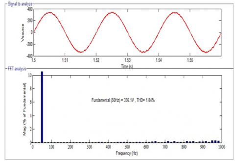
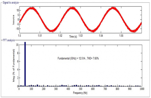
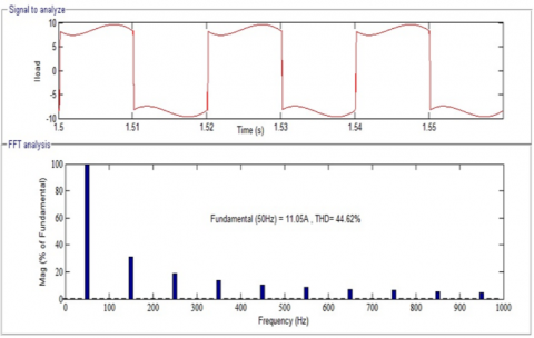
Figure 4. Harmonic spectra of source voltage, source current and load current
The frequency of PWM switching can be increased, decreasing the requirements of the filter and improving performance in the process. The proposed OSG control method for active power filter requires the elimination of the PLL, and it produces source voltages and currents with THD values of 1.84 percent and 7.65 percent respectively are shown in Figure 4, which comply with IEEE-519.
[1] Karimi-Ghartemani, M., Karimi, H. (2007). Processing of symmetrical components in time-domain. IEEE Transactions on Power Systems, 22(2): 572-579. https://doi.org/10.1109/TPWRS.2007.894860
[2] Peng, F.Z., Lai, J.S. (1996). Generalized instantaneous reactive power theory for three-phase power systems. IEEE Transactions on Instrumentation and Measurement, 45(1): 293-297. https://doi.org/10.1109/19.481350
[3] Ghosh, A., Joshi, A. (2000). A new approach to load balancing and power factor correction in power distribution system. IEEE Transactions on Power Delivery, 15(1): 417-422. https://doi.org/10.1109/61.847283
[4] Robles, E., Ceballos, S., Pou, J., Martin, J.L., Zaragoza, J., Ibanez, P. (2010). Variable-frequency grid-sequence detector based on a quasi-ideal low-pass filter stage and a phase-locked loop. IEEE Transactions on Power Electronics, 25(10): 2552-2563. https://doi.org/10.1109/TPEL.2010.2050492
[5] Grady, W.M., Samotyj, M.J., Noyola, A.H. (1990). Survey of active power line conditioning methodologies. IEEE Transactions on Power Delivery, 5(3): 1536-1542. https://doi.org/10.1109/61.57998
[6] Hansen, S., Nielsen, P., Thøgersen, P., Blaabjerg, F. (2001). Line side harmonic reduction techniques of PWM adjustable speed drives: A cost benefit analysis. In Line Side Harmonic Reduction Techniques of PWM Adjustable Speed Drives, 39-46.
[7] Bojoi, R., Griva, G., Profumo, F., Cesano, M., Natale, L. (2008). Shunt active power filter implementation for induction heating applications. COMPEL-The International Journal for Computation and Mathematics in Electrical and Electronic Engineering, 3: 1674-1679. https://doi.org/10.1108/03321640810847733
[8] Chang, G.W., Yeh, C.M. (2005). Optimisation-based strategy for shunt active power filter control under non-ideal supply voltages. IEE Proceedings-Electric Power Applications, 152(2): 182-190. https://doi.org/10.1049/ip-epa:20045017
[9] Afonso, J.L., Couto, C., Martins, J.S. (2000). Active filters with control based on the PQ theory. IEEE Industrial Electronics Society Newsletter, 5-11. https://hdl.handle.net/1822/1921.
[10] Xu, Y., Tolbert, L.M., Peng, F.Z., Chiasson, J.N., Chen, J. (2003). Compensation-based nonactive power definition. IEEE Power Electronics Letters, 1(2): 45-50. https://doi.org/10.1109/LPEL.2003.819915
[11] Kim, S., Todorovic, M.H., Enjeti, P.N. (2003). Three phase active harmonic rectifier (AHR) to improve utility input current THD in telecommunication power distribution system. In Eighteenth Annual IEEE Applied Power Electronics Conference and Exposition, 2003. APEC'03., 2: 805-811. https://doi.org/10.1109/APEC.2003.1179309
[12] Best, R.E. (2007). Phase-locked loops: Design, simulation, and applications. McGraw-Hill Education.
[13] Gardner, F.M. (2005). Phaselock Techniques. John Wiley & Sons.
[14] Newman, M.J., Zmood, D.N., Holmes, D.G. (2002). Stationary frame harmonic reference generation for active filter systems. In APEC. Seventeenth Annual IEEE Applied Power Electronics Conference and Exposition (Cat. No. 02CH37335), 2: 1054-1060. https://doi.org/10.1109/APEC.2002.989374
[15] Depenbrock, M., Staudt, V., Wrede, H. (2003). A theoretical investigation of original and modified instantaneous power theory applied to four-wire systems. IEEE Transactions on Industry Applications, 39(4): 1160-1168. https://doi.org/10.1109/TIA.2003.814553
[16] Karimi-Ghartemani, M., Karimi, H. (2007). Processing of symmetrical components in time-domain. IEEE Transactions on Power Systems, 22(2): 572-579. https://doi.org/10.1109/TPWRS.2007.894860
[17] Newman, M.J., Zmood, D.N., Holmes, D.G. (2002). Stationary frame harmonic reference generation for active filter systems. IEEE Transactions on Industry Applications, 38(6): 1591-1599.
[18] Depenbrock, M., Staudt, V., Wrede, H. (2003). A theoretical investigation of original and modified instantaneous power theory applied to four wire systems. IEEE Transactions on Power Systems, 39(4): 1160-1168.
[19] Rodríguez, P., Pou, J., Bergas, J., Candela, J.I., Burgos, R.P., Boroyevich, D. (2007). Decoupled double synchronous reference frame PLL for power converters control. IEEE Transactions on Power Electronics, 22(2): 584-592. https://doi.org/10.1109/TPEL.2006.890000
[20] Mojiri, M., Karimi-Ghartemani, M., Bakhshai, A. (2007). Estimation of power system frequency using an adaptive notch filter. IEEE Transactions on Instrumentation and Measurement, 56(6): 2470-2477. https://doi.org/10.1109/TIM.2007.908631
[21] Rodriguez, P., Luna, A., Candela, I., Teodorescu, R., Blaabjerg, F. (2008). Grid synchronization of power converters using multiple second order generalized integrators. In 2008 34th Annual Conference of IEEE Industrial Electronics, 755-760. https://doi.org/10.1109/IECON.2008.4758048
[22] Nam, S.R., Park, J.Y., Kang, S.H., Kezunovic, M. (2009). Phasor estimation in the presence of DC offset and CT saturation. IEEE Transactions on Power Delivery, 24(4): 1842-1849. https://doi.org/10.1109/TPWRD.2008.2002972
[23] Mojiri, M., Karimi-Ghartemani, M., Bakhshai, A. (2010). Processing of harmonics and inter-harmonics using adaptive notch filter. IEEE Transactions on Power Delivery, 25(2): 534-542. https://doi.org/10.1109/TPWRD.2009.2036624
[24] Yazdani, D., Mojiri, M., Bakhshai, A., Joos, G. (2009). A fast and accurate synchronization technique for extraction of symmetrical components. IEEE Transactions on Power Electronics, 24(3): 674-684. https://doi.org/10.1109/TPEL.2008.2010321
[25] Ciobotaru, M., Teodorescu, R., Blaabjerg, F. (2006). A new single-phase PLL structure based on second order generalized integrator. In 2006 37th IEEE Power Electronics Specialists Conference, pp. 1-6. https://doi.org/10.1109/pesc.2006.1711988
[26] Bangarraju, J., Rajagopal, V., Jayalaxmi, A. (2013). Reduced DC-link voltage for 6-leg DSTATCOM using IcosØ control algorithm. 2013 Annual IEEE India Conference, pp. 1-6. https://doi.org/10.1109/INDCON.2013.6725949