Barathi Krishna Moorthy* | Pradyumna Kumar Dhal
© 2022 IIETA. This article is published by IIETA and is licensed under the CC BY 4.0 license (http://creativecommons.org/licenses/by/4.0/).
OPEN ACCESS
The primary objective of this study is to meet the energy demands of the power consumer through the implementation of Hybrid Renewable Energy System (HRES) with multiple solar panels and wind turbines. As the photovoltaic (PV) power generation is enveloped with multiple advantageous measures like low maintenance, environmental-friendliness and fuel-efficient, it is significantly preferred in this study. However, the low power conversion quality of PV weakens the overall system and so the DC-DC improved SEPIC converter with magnetic coupling is employed to achieve maximum DC output voltage. In addition, the Adaptive Neuro Fuzzy Inference System (ANFIS) is implemented in this work totrack the maximum power from PV and to maximize the energy efficiency in an optimal manner. The MATLAB Simulink is used to validate the present study with optimal outcomes and the obtained results prove that the present approach delivers lesser THD of 1.00%, which in turn efficiently enhances the overall performance of the system. Thus, the research findings of this system are well suited to be applied as the solution for rectifying the issues in the DC link voltage control and grid compensation or synchronization.
HRES, DQ theory, ANFIS, VSI, PMSG, MPPT
The consequences of climatic changes and global warming have resulted in serious weather events like air contamination, acidic oceans and sea level increasing due to sea ice melting. The use of fossil fuels for meeting everyday energy demands causes the extreme emission of carbon dioxide, which is regarded as one of the key factors of global warming. Therefore, the utilization of Renewable Energy Sources (RES) is encouraged for meeting the future energy demands since it is the apt solution for mitigating the influence of climatic changes and global warming [1, 2]. With the advancement of innovative technologies in the areas of renewable energy and battery, majority of industries have preferred to use RES as it mitigates the energy consumption costs. On the other hand, the HRES attracts the power producers across the world as it comprises low electrification cost. For the efficient power extraction and operation, the HRES remarkably incorporates different renewable sources [3-5]. As the energy produced by the PV cells is extremely low, the voltage boosting DC-DC converter topology is employed, which transform the lower dc voltage into higher level [6].
In general, the DC-DC boost converter is proved to be ideal for this application. However, the requirement of high voltage components increases the conduction losses, which in turn decreases the voltage gain of boost converter. Moreover, the greater duty cycle ratio has an impact on the efficiency and electromagnetic interference [7, 8]. The demerits of boost converter are rectified by implementing the buck boost converter as it consists of two unidirectional ports for utilizing the PV energy and one bidirectional port for recharging the battery. However, the increase in the number of ports, switches and inductors required for the converter raises the complexity of the control circuit [9]. The drawbacks of buck-boost converter are eliminated by employing CUK converter, which reduces the control complexity of the circuit by using soft switching approaches. However, the large quantity of reactive components leads to high current stress across the device, which significantly limits the usage of this converter [10]. To mitigate the demerits of these converters, the SEPIC converter is employed, which continuously generates the input current along with the mitigation of input ripple current and voltage stress in the output [11]. However, the voltage gain of SEPIC converter is still low and it is improved by proposing an improved SEPIC converter topology in this work.
To improve the productivity of solar power under partial shading condition, the Maximum Power Point Tracking method (MPPT) is utilized that tracks the maximum power point (MPP) in the PV module. The major principle of MPPT is to enable the PV panel to generate high power by vaying the operating conditions of the electrical module. The MPPT technique detects the output current and DC voltage, calculates the output power obtained from solar array and tracks the MPP. It efficiently tackles the issues related to any solar system and can be used in solar water pump systems, stand-alone solar power systems, wind-power turbines, water turbines etc. The MPPT algorithms like classical, intelligence, optimization and hybrid algorithm are prevailing in the process of extricating the maximum power from the PV module. However, the effectiveness of these algorithms is determined by the capability of monitoring the MPP under rapidly changing weather condition. The classical MPPT approaches like Incremental Conductance (INC), Perturb and Observe (P&O), Ripple Correlation correction (RCC) and Hill Climbing (HC) are less complex but exhibit oscillation at the output, which results in power loss. On the other hand, the intelligent MPPT techniques have been adopted to achieve the best possible result. The Fuzzy Logic Control (FLC) is a commonly preferred technique, which requires no machine experience for tracking the MPP. However, it owns a complex structure, which significantly limits its usage. Moreover, the ANN is a quicker tracking technique with plenty of beneficial elements but it requires wide data for improving the tracking accuracy. It takes the temperature and varying solar irradiation as inputs and saves these as data sets [12]. Moreover, the selection of the hyperparameters adopted by ANN is crucial for finding the best hyperparameter set because these hyperparameters are used for determining the network structure. Both FLC and ANN are used for solving nonlinear problems but FLC involves the framing of rules and membership functions while ANN requires training data and learning algorithms. For the effective tracking of maximum power, a new hybrid algorithm called ANFIS is formed by combining the advantages of both FLC and ANN algorithms. In this combined approach, the tracking is performed in two stages, among which the MPP is estimated in the first stage and the attributes of the measured MPP is tuned well by using innovative techniques in the second stage.
The contribution of Wind Energy Conversion System (WECS) in global energy supply [13] has been increasing tremendously. The Induction generator (IG) and Synchronous generator (SG) are the two types of generators widely used in wind turbines. The induction generators are robust and easy to implement but it needs exciting current from some other external sources. The IG runs only at high speed but the SG runs at adjustable rotational speeds like low, medium and high. Due to various advantages like extreme reliability, optimum performance and maximum power density, the Permanent Magnet Synchronous Generators (PMSG) based WECS has gained much attention [14-18]. In order to obtain high quality control system, the implementation of closed loop PI control strategy is performed. The control strategy employs a PI controller that is self-tuned by a set of parameters and suitable closed loop response [19]. The grid connected $3 \phi$ inverter with LC filter has been carefully configured to control the current and to ensure smooth working by mitigating the background harmonics or distortions [20, 21].
In this work, the grid tied HRES system with battery is verified, in which the PV voltage is boosted by employing an improved SEPIC converter. The maximum power point is tracked by employing ANFIS based MPPT technique, which aids in improving the overall power production. In order to achieve higher performance in WECS, the PMSG is employed. The AC to DC conversion takes place with the help of AC-DC PWM rectifier, which is regulated by means of a closed loop PI controller. The grid synchronization is accomplished with unity power factor by regulating the inverter with the assistance of using dq theory.
Figure 1 illustrates the proposed control scheme of hybrid PV-wind turbine energy generation system in an efficient manner.
2.1 Modeling of the proposed scheme
The hybrid PV-wind system generates improved outputs from the wind turbine during windy season whereas during sunny conditions, the PV system generates peak results. The combination of these two sources overcomes the demerits of both sources. Generally, a hybrid system comprises of wind turbine, solar PV, battery, inverter and other additional components determining the operation of the hybrid system. Depending on the availability, the energy sources supply the grid separately or simultaneously. In order to generate maximum power, each source operates on its maximum power point. This hybrid system minimizes the requirements of diesel and battery bank, hence when compared to similar systems, the generated electricity is cheaper.
Figure 1. Framework of proposed PV-Wind turbine hybrid system
2.1.1 PV panel model
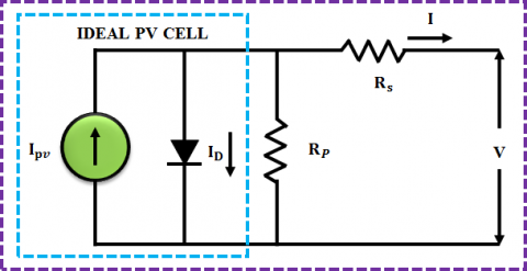
This section describes the semiconductor-based model of a PV module with 36 solar cells. Multiple photovoltaic cells are arranged in series or parallel for generating solar panels. During the series configuration, the voltage gets increased and the current is maintained as constant whereas in the parallel configuration, the current gets increased and the voltage is maintained as constant. $N_{s}$ and $N_{p}$ respectively denotes the total solar cells linked in series and parallel. The total photo current, which is induced by cell temperature and solar irradiation is given as $N_{p} I_{p h}$. The one diode circuit diagram of PV system is given in Figure 2.
Figure 2. One diode circuit illustration of PV system
The expression that relates the output voltage and current is given as,
$I_{P V}=I_{p h}-I_{0}\left[e^{\frac{q\left(V_{P V} \ + I_{P V} \ R_{s}\right)}{N_{s} \ k n T}}-1\right]-\frac{V_{P V}+I_{P V} \ R_{s}}{R_{s h}}$ (1)
where, $I_{P V}$ denotes the output current produced by the PV module, $V_{P V}$ indicates PV resultant voltage, $I_{p h}$ indicates photo current, $I_{0}$ denotes the reverse saturation current, $\mathrm{q}$ indicates electron charge and its value is noted as $1.602 \times$ $10^{-19} \mathrm{C}$, $\mathrm{n}$ represents the ideality factor of $\mathrm{PV}$ cell, $\mathrm{k}$ indicates the Boltzmann's constant $\left(k=1.3806 \times 10^{-23} J / K\right)$, $\mathrm{T}$ denotes PV celltemperature, $R_{s}$ and $R_{s h}$ denote the resistance connected in series and parallel.
2.1.2 Improved SEPIC converter model
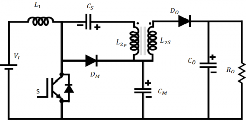
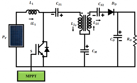
The duty cycle of the SEPIC converter without magnetic coupling is set as high in order to achieve the optimum voltage gain. As a result, a secondary winding is included in the $L_{2}$ without magnetic coupling, which increases the voltage gain ratio without increasing the duty cycle or switch voltage. The inductor windings turn ratio (n) raises the voltage at output. In addition, the other benefits of Improved SEPIC are: Generates non-inverted voltage at the output, reduction of electromagnetic interference due to non-pulsating input current and improved efficiency with reduced output ripple. The Improved SEPIC converter utilizing magnetic coupling is displayed in Figure 3.
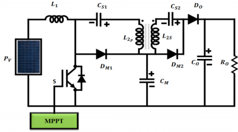
However, the accumulated energy in the leakage inductance creates a voltage ring and increases a reverse voltage at Do. All these issues are occurred by presence of reverse recovery current Do. In order to rectify this overvoltage issue, the voltage multiplier is mounted on the secondary side. The voltage multiplier maximizes the voltage gain while reducing the reverse voltage than the output voltage. In addition, it allows the stored energy in the leakage inductance to be transmitted to the output. As a result, the clamping circuit using a voltage multiplier with Dm2 and Cs2 becomes non-dissipative to Do. The equivalent connection diagram of improved SEPIC converter with output diode clamping is vividly shown in Figure 4.
Figure 3. Improved SEPIC converter utilizing magnetic coupling
Figure 4. Improved SEPIC converter with output diode clamping
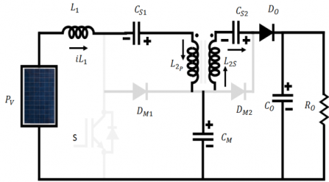
Working of improved SEPIC converter. Five stages of operation occur in the improved SEPIC converter with output diode clamping and it also operates in continuous current conduction mode (CCM) as mentioned in Figures 5-9. All the semiconductors are ideal and the capacitors are the voltage source for the converters.
Stage 1
Figure 5. Stage 1
During this time, switch S is in on state, energy is stored in inductor $L_{1} \cdot L_{2 s}$ and $D_{m 2}$ charges the capacitor $C_{s 2}$. Current is regulated by leakage inductance and the energy is transferred in a resonant manner. The reverse voltage $D_{o}$ becomes obstructed and the maximal $D_{o}$ voltage becomes equal to $V_{o}-$ $V_{c m}$. At the end of this step, the energy transmission to the capacitor $C_{s 2}$ is completed and $D_{m 2}$ is obstructed.
Stage 2
$D_{m 2}$ is blocked at this stage and the energy is stored in inductors $L_{1}$ and $L_{2}$.
Figure 6. Stage 2
Stage 3
In this stage, switch $\mathrm{S}$ is turned off and the energy accumulated in the inductance $L_{1}$ is converted to $C_{m}$. In addition, the energy is transmitted to output through the capacitor $\left(C_{s 1}\right.$ and $\left.C_{s 2}\right)$, inductor $L_{2}$ and the diode $D_{o}$.
Figure 7. Stage 3
Stage 4
When the energy transmitted to the capacitor $C_{m}$ is completed, diode $D_{m 1}$ is turned off. The energy is transferred to the resultant during this stage.
Figure 8. Stage 4
Stage 5
The switch is in ON condition at this stage and the diode current of Do linearly decreases. When the transformer leakage inductance limits di/dt. it limits the reverse recovery current restriction Do. When the diode Do is blocked, the converter gets reverted to the initial level.
Figure 9. Stage 5
The voltage gain is given as,
$\frac{V_{0}}{V_{\text {in }}}=\frac{1}{(1-D)} \times(1+n) \cdot: n=\frac{N_{L 2 s}}{N_{L 2 p}}$ (2)
where, n is the winding turn ration of inductor. The voltage gain is increased by the value of n without increasing the switch voltage. Thus the duty cycle is given as,
$D=1-\frac{V_{i n}}{V_{0}} \times(1+n)$ (3)
The switch and diode voltage are given as,
$V_{s}=V_{D m 1}=\frac{V_{i n}}{(1-D)}$ (4)
The diodes $D_{m 2}$ and $D_{o}$ produce same voltage, which is given as,
$V_{D_{0}}=V_{D m 2}=V_{0}-V_{c m}=n \times \frac{V_{i n}}{(1-D)}$ (5)
The value of inductance $L_{1}$ is given as
$L_{1}=L_{2 p}=\frac{\left(V_{i n} \times D\right)}{(1-D)} L_{2 s}=n^{2} \times L_{2 p}$ (6)
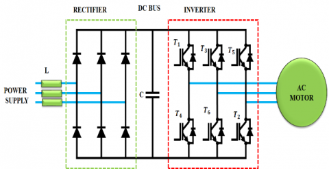
2.3 Three-phase inverter
The basic $3 \Phi$ Voltage Source Inverter (VSI) is depicted in Figure 10. As the variability in sunlight and wind speed has a direct impact on the energy production, the output power has a significant effect on the sensitive regulation of the system, which in turn decreases the electric distribution's efficiency and reliability. The basis of this inverter is to convert the DC voltage into AC for compensating the load voltage in an efficient manner. The inverter is common for both PV and wind systems as it converts the combined DC voltage obtained at the DC link. Thus, it remarkably assists in the process of accomplishing grid synchronization and energy transformation in an optimal manner.
Figure 10. Basic three phase voltage source inverter
2.4 Pulse width modulation
In two steps, an ideal voltage-source inverter converts the frequency and voltage. Though the three-phase six-step inverter is simple to work, it delivers high distortion of current wave in the absence of filter. In high-powered systems, the PWM procedures are used to reduce the occurrence of harmonics. The aim of employing these modulating methods is to obtain a superior and regulated output from the inverters without any harmonics and distortions. Depending on the requirement of performance, the PWM procedures are employed in multiple ways.
2.5 ANFIS MPPT
Figure 11. ANFIS MPPT architecture
This advanced method effectively extracts the MPP from PV arrays under varying weather conditions. This MPPT is often used to create a proper MF distribution with the perfect shape and position. The mapping of inputs to outputs, the design and distribution of MFs and the establishment of fuzzy rules using FLC and ANN are the parts of this method. The key benefit of this approach is its intrinsic adaptive learning capability independent of the training data deviation. Figure 11 denotes the ANFIS MPPT architecture, which consists of six layers and each with two input parameters. The ANFIS method rigorously trains three MFs for these input parameters. In order to generate the maximum output power, nine fuzzy rules are extracted after mapping both the input and output. The fuzzy rules are formed based on the input data and the rules are further redefined by the neural network. In general, the role of ANFIS is to track the maximum power with high accuracy under varying irradiance. It generates the crisp values related to the maximum power obtained from the PV module.
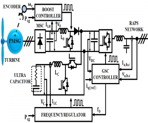
2.6 PMSG based WECS
Figure 12 illustrates the Configuration of PMSG based wind turbine. The back-to-back converter scheme's machine-side converter (MSC) is an unregulated diode-bridge that rectifies the $3 \Phi$ voltage of PMSG. Through the boost converter, the MSC output voltage is coupled with the DC-link. The grid side converter (GSC) performs the inversion of DC-link voltage and connects it to the grid through a filter. Grid voltage centered reference frame is used to power the GSC by the alignment of d-axis with grid voltage. As a result, the d-axis and q-axis components have respectively controlled the active and reactive power. To optimize the wind energy extraction, WECS are usually regulated by utilizing a MPPT approach. The wind turbine’s standard MPPT curve is fitted to the polynomial of third degree (2).
$P_{m}^{*}=0.750 \omega_{r}^{3}-0.001 \omega_{r}^{2}+0.001 \omega_{r}$ (7)
Here $P_{m}^{*}$ indicates the power output reference of wind turbine and ωr indicates the rotational speed of rotor. A portion of the available wind power is stored in the wind turbine to improve the frequency response generated by the WECS.
Figure 12. Configuration of PMSG based wind turbine
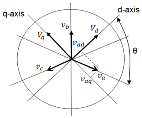
2.7 DQ0 theory
The d and q axes components of the voltage and current waveforms are respectively obtained from the grid and inverters. The orthogonal equipments are utilized for accomplishing the grid synchronization. The synchronization of grid is achieved with independently controlling the orthogonal equipment in DQ controller. The $d q 0$ transformation diagram is shown in Figure 13. In $d q 0$ theory, the $3 \phi$ signals in the abc reference frame are mapped to $d q 0$ reference frame. Here, θ indicates the reference angle, $\omega_{s}$ denotes the frequency, $d$ indicates the direct, $q$ indicates the quadrature and 0 indicates the zero components. The $3 \phi$ signals are mapped as constants and the voltages are given by:
$v_{a}=A \cos \left(\omega_{s} t\right)$ (8)
$v_{b}=A \cos \left(\omega_{s} t-\frac{2 \pi}{3}\right)$ (9)
$v_{c}=A \cos \left(\omega_{s} t+\frac{2 \pi}{3}\right)$ (10)
Figure 13. dq0 transformation diagram
he proposed work is implemented in MATLAB and the outcomes are obtained in an optimal manner as specified in the subsequent section. The attained resultant voltage of the solar panel is 72V and is displayed in Figure 14. Figure 15 illustrates the input current waveform of improved SEPIC Converter.
Figure 14. Solar panel output voltage waveform
Figure 15. Input current of the converter
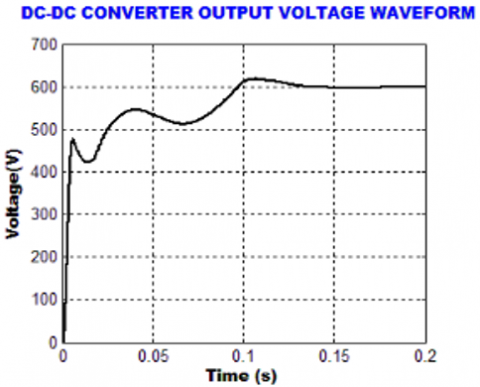
Figure 16. Waveform of converter output voltage
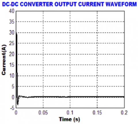
Figure 17. Waveform of DC-DC converter output current
Figure 18. WECS output voltage waveform
Figure 19. PWM rectifier Output Voltage Waveform
The output voltage and current waveforms of improved SEPIC converter are portrayed in Figure 16 and 17 respectively.
The waveform of output voltage of WECS is given in Figure 18, which displays that the output voltage varies from +600 to -600V.
The waveform representing the output voltage of PWM rectifier is given in Figure 19, which proves that the initial oscillations in the voltage are eliminated after the period of 0.17s.
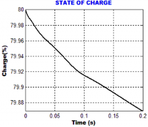
Figure 20. State of charge
Figure 21. Battery voltage waveform
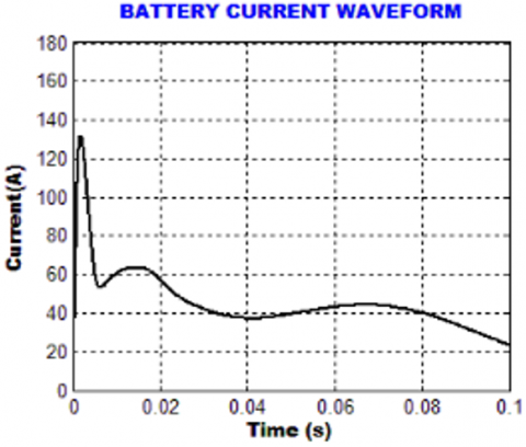
Figure 22. Battery current waveform
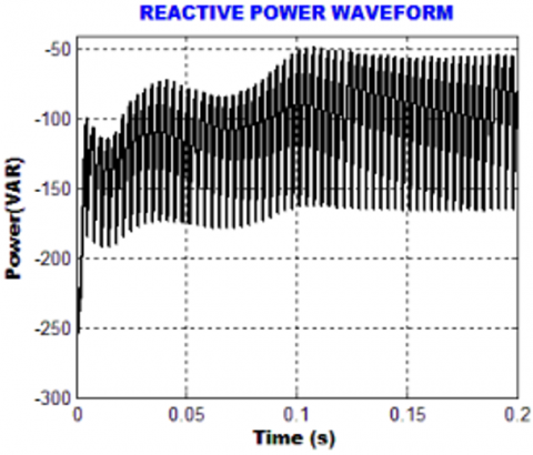
Figure 23. Reactive power waveform
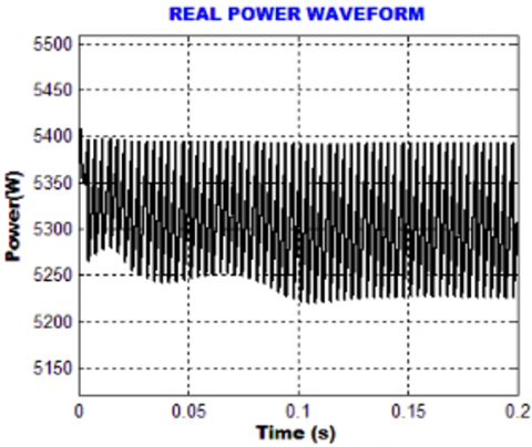
Figure 24. Real power Waveform
The state of charge, battery voltage and current waveforms are shown in Figure 20, 21 and 22 respectively.
The waveforms of reactive power and real power are given in Figure 23 and 24 respectively.
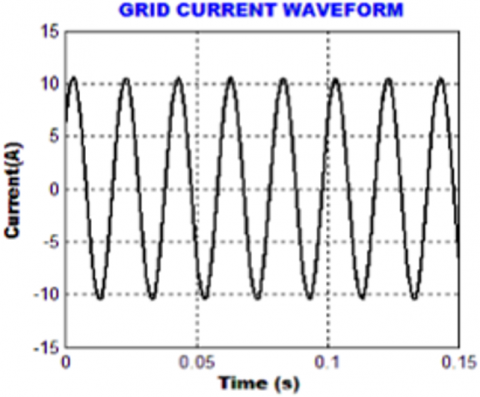
The output grid voltage and current waveform are given in Figure 25 and 26.
Figure 27 shows the THD representation of grid current in an efficient manner. It is noted from the figure that the source current THD of 1.00% is attained.
Figure 25. Grid voltage waveform
Figure 26. Grid current waveform
Figure 27. THD grid current waveform
On the whole, the proposed approach generates improved values for the hybrid system. An input voltage of 70V is increased to 600V indicating a high voltage gain ratio. Moreover, a rectified output 600V is obtained from wind system and a voltage of 175V is maintained in the battery. Finally, an improved grid synchronization is obtained with a reduced THD of 1%.
The significance of ANFIS based SEPIC converter in the process of energy generation is phenomenally expounded in this present work. The low output voltage of PV is remarkably maximized through the implementation of an improved SEPIC converter with a low-cost control circuit, which retains a constant output voltage in an optimal way. The MPP is significantly tracked with the aid if using ANFIS approach, which is capable enough in providing optimal outputs with increased efficiency. The optimized converter output is fed to the grid through a 3Φ VSI after eliminating the disruptions with the aid of LC filter. The entire work is validated in MATLAB Simulink and the outputs prove that the introduced approach delivers lesser THD of 1.00%, which is highly optimum in enhancing the overall performance of the system.
[1] Elavarasan, R.M., Shafiullah, G.M., Padmanaban, S., Kumar, N.M., Annam, A., Vetrichelvan, A.M., Holm-Nielsen, J.B. (2020). A comprehensive review on renewable energy development, challenges, and policies of leading Indian states with an international perspective. IEEE Access, 8: 74432-74457. https://doi.org/10.1109/ACCESS.2020.2988011
[2] Dinh, H.T., Yun, J., Kim, D.M., Lee, K.H., Kim, D. (2020). A home energy management system with renewable energy and energy storage utilizing main grid and electricity selling. IEEE Access, 8: 49436-49450. https://doi.org/10.1109/ACCESS.2020.2979189
[3] Babatunde, O.M., Munda, J.L., Hamam, Y. (2020). A comprehensive state-of-the-art survey on hybrid renewable energy system operations and planning. IEEE Access, 8: 75313-75346. https://doi.org/10.1109/ACCESS.2020.298839
[4] Singh, R., Bansal, R.C. (2018). Optimization of an autonomous hybrid renewable energy system using reformed electric system cascade analysis. IEEE Transactions on Industrial Informatics, 15(1): 399-409. https://doi.org/10.1109/TII.2018.2867626
[5] Habib, H.U.R., Wang, S., Elkadeem, M.R., Elmorshedy, M.F. (2019). Design optimization and model predictive control of a standalone hybrid renewable energy system: A case study on a small residential load in Pakistan. IEEE Access, 7: 117369-117390. https://doi.org/10.1109/ACCESS.2019.2936789
[6] Forouzesh, M., Siwakoti, Y.P., Gorji, S.A., Blaabjerg, F., Lehman, B. (2017). Step-up DC–DC converters: A comprehensive review of voltage-boosting techniques, topologies, and applications. IEEE Transactions on Power Electronics, 32(12): 9143-9178. https://doi.org/10.1109/TPEL.2017.2652318
[7] Faridpak, B., Bayat, M., Nasiri, M., Samanbakhsh, R., Farrokhifar, M. (2020). Improved hybrid switched inductor/switched capacitor DC–DC converters. IEEE Transactions on Power Electronics, 36(3): 3053-3062. https://doi.org/10.1109/TPEL.2020.3014278
[8] Liu, H., Ji, Y., Wang, L., Wheeler, P. (2017). A family of improved magnetically coupled impedance network boost DC–DC converters. IEEE Transactions on Power Electronics, 33(5): 3697-3702. https://doi.org/10.1109/TPEL.2017.2763153
[9] Chandrasekar, B., Nallaperumal, C., Padmanaban, S., Bhaskar, M.S., Holm-Nielsen, J.B., Leonowicz, Z., Masebinu, S.O. (2020). Non-isolated high-gain triple port DC–DC buck-boost converter with positive output voltage for photovoltaic applications. IEEE Access, 8: 113649-113666. https://doi.org/10.1109/ACCESS.2020.3003192
[10] Khodabandeh, M., Afshari, E., Amirabadi, M. (2019). A family of Ćuk, Zeta, and SEPIC based soft-switching DC–DC converters. IEEE Transactions on Power Electronics, 34(10): 9503-9519. https://doi.org/10.1109/TPEL.2019.2891563
[11] Moradpour, R., Ardi, H., Tavakoli, A. (2017). Design and implementation of a new SEPIC-based high step-up DC/DC converter for renewable energy applications. IEEE Transactions on Industrial Electronics, 65(2): 1290-1297. https://doi.org/10.1109/TIE.2017.2733421
[12] Bollipo, R.B., Mikkili, S., Bonthagorla, P.K. (2020). Hybrid, optimal, intelligent and classical PV MPPT techniques: A review. CSEE Journal of Power and Energy Systems, 7(1): 9-33. https://doi.org/10.17775/CSEEJPES.2019.02720
[13] Ahmed, S.D., Al-Ismail, F.S., Shafiullah, M., Al-Sulaiman, F.A., El-Amin, I.M. (2020). Grid integration challenges of wind energy: A review. IEEE Access, 8: 10857-10878. https://doi.org/10.1109/ACCESS.2020.2964896
[14] Toulabi, M., Bahrami, S., Ranjbar, A.M. (2017). An input-to-state stability approach to inertial frequency response analysis of doubly-fed induction generator-based wind turbines. IEEE Transactions on Energy Conversion, 32(4): 1418-1431. https://doi.org/10.1109/TEC.2017.2696510
[15] Thakallapelli, A., Kamalasadan, S., Muttaqi, K.M., Hagh, M.T. (2019). A synchronization control technique for soft connection of doubly fed induction generator based wind turbines to the power grids. IEEE Transactions on Industry Applications, 55(5): 5277-5288. https://doi.org/10.1109/IAS.2017.8101767
[16] Yousefian, R., Bhattarai, R., Kamalasadan, S. (2017). Transient stability enhancement of power grid with integrated wide area control of wind farms and synchronous generators. IEEE Transactions on Power Systems, 32(6): 4818-4831. https://doi.org/10.1109/TPWRS.2017.2676138
[17] Errouissi, R., Al-Durra, A. (2017). A novel PI-type sliding surface for PMSG-based wind turbine with improved transient performance. IEEE Transactions on Energy Conversion, 33(2): 834-844. https://doi.org/10.1109/TEC.2017.2776752
[18] Lyu, X., Zhao, J., Jia, Y., Xu, Z., Wong, K.P. (2018). Coordinated control strategies of PMSG-based wind turbine for smoothing power fluctuations. IEEE Transactions on Power Systems, 34(1): 391-401. https://doi.org/10.1109/TPWRS.2018.2866629
[19] Errouissi, R., Al-Durra, A. (2018). Design of PI controller together with active damping for grid-tied LCL-filter systems using disturbance-observer-based control approach. IEEE Transactions on Industry Applications, 54(4): 3820-3831. https://doi.org/10.1109/TIA.2018.2823258
[20] Su, M., Cheng, B., Sun, Y., Tang, Z., Guo, B., Yang, Y., Wang, H. (2019). Single-sensor control of LCL-filtered grid-connected inverters. Ieee Access, 7: 38481-38494. https://doi.org/10.1109/ACCESS.2019.2906239
[21] Zheng, F., Wu, W., Chen, B., Koutroulis, E. (2020). An optimized parameter design method for passivity-based control in a LCL-filtered grid-connected inverter. IEEE Access, 8: 189878-189890. https://doi.org/10.1109/ACCESS.2020.3032038