Gashaw A. Anagie* | Abdulkadir A. Hassen | Yihun T. Sintie
© 2021 IIETA. This article is published by IIETA and is licensed under the CC BY 4.0 license (http://creativecommons.org/licenses/by/4.0/).
OPEN ACCESS
Wind energy is a vital energy free from pollution and freely available energy in our world. The purpose of this research is performance investigation of small horizontal axis wind turbine installed at the top of a pickup vehicle and the power generated from this wind turbine is used to charge the batteries of the vehicle. Permanent magnet generator is selected for the experiment as well as the selected type of the blade is NACA 4412 and its angle of attack is 6°. The angle of attack is determined by using Qblade software at the maximum lift to drag ratio of NACA 4412 airfoil. The blades of wind turbine are fabricated from wood because wood have excellent fatigue properties. The comparison between analytical analysis and experimental test is done based on the reaction wind speed, in order to achieve good matching between analytical analysis and experimental test. Finally, the power output from the wind turbine is used for charging the vehicle battery and the charging process is controlled by regulator. The maximum powers determined from the experimental and theoretical analysis are 334 W and 437 W at reaction wind speed of 28.6m⁄s respectively at the maximum vehicle speed of 25m⁄s.
attack angle, battery, regulator, vehicle mounted wind turbine, and small wind turbine
Renewable energy sources offer limitless resource and environment friendly operation compared to conventional energy sources. There are several forms of renewable energy such as solar energy, wind energy, geothermal energy, tidal energy, hydro energy and bioenergy. Be that as it may, wind energy is the most important, protected and quickest developing sustainable power source. Wind energy outshines all other renewable energy resources due to the recent technological development. Electrical energy generation from wind energy has increased rapidly and due to the increased interest, many studies on efficient wind turbine design have been performed. Nowadays, electrical energy from wind turbines is classified as the most efficient and important than other green energy resources. This remarkable development can be primarily attributed to the development in the large wind turbines technology. However, small wind turbines are still in their developmental stage. In the past decades, the installed power capacity of large wind turbines displayed an annual growth rate of about 30% whereas the small wind turbines revealed only 9% [1].
Generator, alternator and motor are the main component of small wind turbines, which converts the mechanical energy into electrical one. Most of the time generator is used to change mechanical energy in to electrical one. Thus, by reducing the cost of generators in such turbines would certainly lower their overall cost, making them cost competitive. A major reason for the lessened utilization of big wind turbines is due to the fact that the current systems make use of high quality generators that are expensive. The earlier study of the energy has successfully yielded commercially available small wind turbines which shows that the cost of generated electricity from small wind turbines are the most cost effective [2].
In the life of human beings, all activities are done by the use of energy. Percent consumption of conventional energy is higher in our country Ethiopia than percent consumption of non-conventional energy sources. But conventional energy sources are not environmentally friendly. Due to these reasons, we must replace conventional energy by non-conventional energy such as wind energy, solar energy, geothermal energy, hydro power etc. Although wind power plants contribute to electrical energy generation, they are built far away from consumption centers due to several factors such as, - noise problems, large area needed (not suitable for urban centers), and complex construction. Therefore, a new wind turbine design for the cities, which has a low wind speed profile area and high population density considerations, become a critical need. By depending on the above problem this research concerns to generate electricity from the low wind speed and the speed of the vehicles and giving the people the way of simplifying their life using electricity and greenhouse effect by designing a vehicle mounted wind turbine installed over the roof of the vehicle of their electric consuming car to charge their battery.
The objective of this paper is to evaluate the power produced from small wind turbine by using generator and determines the feasibility of installing a small horizontal axis wind turbine on top of a pickup vehicle.
The experimental investigation is performed with the objective of determining the amount of power and whether it is sufficient to charge a battery or not.
A lot of researches have been done throughout the world on small horizontal axis wind turbine installed over a vehicle as well as experimental investigation was done by using wind tunnel.
According to Awol et al. [3] study, they did design and implementation of vehicle mounted wind turbine on a pick up vehicle. The type of wind turbine is horizontal axis wind turbine. They also evaluate the VMWT performance in terms of power generation. It is shown that, with proper designing, VMWT can generate approximately 200 W of power at vehicle speed of 80 km/hr. the main gaps of this research works are the installation area of the turbine and the efficiency of their generator.
Saad et al. [4] conducted a study on small horizontal axis wind turbine under high speed operation. These wind turbines are installed over a vehicle and generates power under high speed with small sweep area and had good performance. The researchers did numerical analysis and experiments. The numerical and experiments analysis is worked at a minimum and maximum vehicle speed of 22.22 $\mathrm{m} / \mathrm{s}$ and 33.33 $\mathrm{m} / \mathrm{s}$ respectively and their results are related to each other. The main gaps of this research work are the wind turbines were installed at the back of the vehicles top area.
According to Quartey et al. [5], they investigate the design of a wind turbine that will be mounted on the electric car to generate electrical power to charge the car batteries when in motion. The turbine is positioned on the roof of the car near the wind screen, where the velocity of air flowing around the car is highest due to its aerodynamic nature. A portable horizontal axis diffuser augmented wind turbine is adopted for the design since that is able to produce a higher power output as compared to the conventional bare type wind turbine. The current is generated by the car when it begins to move. Through the theoretical calculation on the power generated from the wind, a significant amount of 3.26 kW electrical powers is obtained. The main gaps of this research works are not experimental.
To our knowledge and based on the literature reviewed, no attempt was made previously to design the type of blade we considered in this study on top of a vehicle, and no previous similar research work is reported specific to the Ethiopian whether condition.
Accordingly, we decided to do performance investigation of vehicle mounted small wind turbine installed over the front top area of the pickup vehicle to charge electric vehicle battery.
The focus of this research works is design, selection of materials and manufacturing of blades, result and discussion as well as conclusions are included.
The first target of this paper is to generate enough power to charge electric consuming vehicle batteries. To generate enough power the main focus is on manufacturing and selecting the basic components of the wind turbine, specifically the blades and generators as well as choosing the right profiles of NACA blades having high lift and low drag force airfoils. In addition to that choosing the right materials which have low cost, good fatigue resistance, availability, maintainability, and easy of manufacturing. The technique of this paper is specifically based on literature overview of published study papers and books regarding the manufacturing, and their different outcomes.
2.1 Radius of the rotor (r)
In this analysis the radius of the rotor primarily depends on the top flat areas of the pickup vehicle which is 2.16 m2. That is the maximum width of the top of the vehicle is 1800 mm and Length 1200 mm. So that the output power mainly depends on the vehicle speed, V, the density of air, $\rho_{\text {air }}$ as well as the rotor radius, R So that the radius of the rotor is decided to be 250 mm. Based on the traffic rule and regulation, it is not allowed to exceed 30% of the overall length of the vehicle [6].
Rotor swept area, $\mathrm{A}_{\mathrm{S}}$ is calculated using Eq. (1).
$A_{s}=\pi R^{2}=3.14^{*}(250)^{2}=196,250 \mathrm{~mm}^{2}$ (1)
where, $\mathrm{A}_{\mathrm{S}}$ is the swept area of the rotor, and R is the radius of the rotor.
Density of dry air at 2300 meter altitude of Gondar calculated by using pressure of air and average temperature of air at that altitude as presented in Eq. (2).
$\rho_{\text {air }}=3.4837 \frac{P r_{\text {air }}}{T}=3.4837 * \frac{(78.2) \mathrm{Kpa}}{291.91 \mathrm{~K}}=0.93 \mathrm{~kg} / \mathrm{m}^{3}$ (2)
Figure 1. Reaction wind speed measuring at the top of a pickup vehicle by using Anemometer at a variable speed of a vehicle
Figure 1 Shows that the measurements of the reaction wind speed at the top of the vehicles using anemometer when the vehicle is moving.
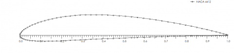
The maximum power coefficient of small horizontal axis wind turbine is 35% are taken as well as the selected Generator has a capacity of 0.37 kW and three numbers of blades are selected. A rotor with even number of blades has a stability problem for a machine with a stiff structure in practical. Odd number of blades has good stability in balancing [7]. Three number of blades are selected having a tip speed ratio, $\lambda$=7. The Selected of types airfoil are NACA 4412 as shown in Figure 2.
Figure 2. Asymmetrical shapes of 4 digit-(NACA 4412) airfoil
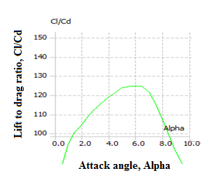
Figure 3. Attack angle, α vs. lift to drag coefficient ($\mathrm{C}_{\mathrm{L}} / \mathbf{C}_{\mathbf{D}}$)
As presented in Figure 3 the angle of attack at the maximum lift to drag (124.6) ratio is 6°.
Chord length of the airfoil can be calculated as using Eq. (3) and (4).
$C=\frac{8 \pi R}{B C_{L}}(1-\cos \phi)$ (3)
Or
$\frac{C}{R}=0.075$ and $\frac{C}{R}=0.5$ (4)
2.2 Solidity ($\sigma_{r}$) of the turbine blades
The solidity is calculated using Eq. (5).
$\sigma_{\mathrm{r}}=\frac{\mathrm{BC}}{2 \pi \mathrm{r}}$
$\sigma_{r}=\frac{3 * 0.035}{2 \pi * .218}=0.08$ (5)
where, B is number of blades, C is chord of an airfoil and r is the radius of the blades. The solidity of the blade is below one so that its good and acceptable based on international standards.
Blades in a regularly working wind turbine rotor are continuously exposed to cyclical loads from wind and gravity. The expected lifetime for a blade is usually 20 years for large wind turbines, and less than 20 years for small wind turbines [8]. Based on these conditions, in the wind turbine industry, many materials have been used for blades, including metals, plastics, wood and composites. Juniper is selected as blade materials.
2.3 Blade fabrication
From the analytical analysis rotor radius starts from the center, R = 250 mm, and radius, r = 218 mm as well as the length of the blades which have aerodynamic shape are 180 mm. The maximum thickness of the blades is 5 mm and the maximum chord of the blades, C = 35 mm. Initially we select rectangular shape of wood having 10 mm thickness and 218 mm span length as shown in Figure 4.
Figure 4. Initial shape of blade before manufacturing NACA profiles
Initially we select rectangular shape of wood having 10 mm thickness and 218 mm span length shown in Figure 4 and prepared it to the shape of the airfoil as shown in Figure 5.
Figure 6 shows the assembly of small wind turbine and testing its power output by using multi meter when the vehicle is in motion.
Figure 5. Overall assembly of rotors of wind turbine
Figure 6. Overall assembly
2.4 Analytical and experimental methods
2.4.1 Analytical analysis
Overall power of the wind turbine, $P_{a l l}$ is obtained using Eq. (6) as follows:
$P_{a l l}=\frac{1}{2} \rho_{a i r} A_{S} V_{a v}^{3} C_{p} \eta_{t} \eta_{a}$ (6)
where,
In this research we use to couple the wind turbine rotor directly with the generator so that the efficiency of the gear train is one ($\eta_{t}=1$) mean no gear train at all [5].
For the sake of design and as it is difficult to measure the reaction wind speed above vehicle speed of 25 m/s, we decided the cutout speed of the turbine to be 28.6 m/s of reaction wind speed. Based on Eq. (7) and the reasons written in the above topic we can determine the overall power as:
$P_{a l l}=\frac{1}{2} \rho_{a i r} A_{S} V_{a v}{ }^{3} C_{p} \eta_{t} \eta_{a}=0.5 * 1.21 *$
$0.35 * 0.196 * 0.90^{*} 1^{*}(28.6)^{3}=437 \mathrm{~W}$ (7)
2.5 Electrical power determination
The electrical power is calculated using Eq. (8) as follows:
$P_{E}=V_{E} * I * \cos \emptyset=\frac{V_{E}^{2}}{R} \cos \emptyset$ (8)
where, $P_{E}$ = electrical power, $V_{E}$= voltage determined from electrical device, $\theta$=power factor of the device and current, $\emptyset$ = phase angle between voltage and current and R = field resistance of the electrical machine. The power factor of single phase motor which is used as a generator is 0.84 for fully conditions [10, 11].
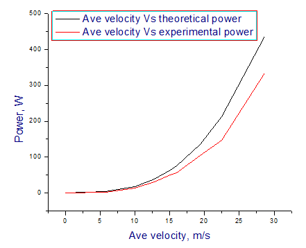
The data in Table 1 and presented in Figure 7 shows the relationship between the average velocity of the reaction wind speed at the top of the vehicle with the theoretical as well as the experimental power output of the installed turbine. Basically, the graph shows that experimental power output is less than theoretical power output at the same velocity. This is expected as the theoretical analysis fails to account all losses during operation.
Table 1. Analytical and experimental analysis power at average velocity of reaction wind speed
|
Ave velocity, m/s |
Theoretical power, watt |
Experimental power, watt |
|
0 |
0 |
0 |
|
5.74 |
3.53 |
2.76 |
|
9.96 |
18.45 |
13.78 |
|
12.8 |
39.20 |
30.50 |
|
15.1 |
64.30 |
49.97 |
|
16.0 |
76.5 |
56.03 |
|
19.33 |
135 |
105.00 |
|
22.5 |
212.74 |
146.50 |
|
28.6 |
436.91 |
333.61 |
Figure 7. Average reaction velocities vs. analytical analysis and experimental analysis power
3.1 Analytical and experimental analysis results and interpretation
The average reaction wind speeds are determined by measuring the reaction wind speed for 2 minutes by driving the vehicle at a constant speed for example for 20 $\mathrm{km} / \mathrm{hr}$ and determines the average velocities. Based on this analysis the cut in and cutout wind speed of the turbine are 5.74 $\mathrm{m} / \mathrm{s}$ and 28.6 $\mathrm{m} / \mathrm{s}$ respectively. The reaction wind speed is greater than the vehicle speed due to the addition of environment wind speed.
The solidity of the rotor is less than one. So that the solidity of our designed wind turbine rotor is 0.08, less than one it’s good.
The generated lift force is greater than drag force this is the main aim of selecting the aerodynamic profiles of the blades. The selected blades profiles were NACA 4412 and it can generate lift force at zero angle of attack. The generated lift forces, L = 4948 N and drag force, D = 39 N.
Blades are manufactured from NACA 4412 airfoils and the materials have good fatigue properties. Due to this property blade of the turbine resist cyclic loading as well as its weight is light. This blade has maximum thickness at 30% of the chord and is 12% of the chord and its 5 mm thick.
Powers generated from theoretical and experimental analysis were 437 W and 334 W respectively at the cutout speed of the turbine.
Finally, the generated power is used to charge the electric vehicle battery, to charge the battery a controlling device is mandatory. So that regulator is used to control the up and down of the voltage generated and used to change AC to DC.
This wind turbine has a radius of 250mm, three numbers of blades and 0.5 horsepower generators. The profiles of the blades are NACA 4412 and cambered type. The blades are manufactured from wood because it has high fatigue resistance properties as well as its low cost.
The wind turbine is appropriately designed to extract maximum amount of energy from the wind to power the electric car battery. Through the analytical analysis on the power generated from the wind, a significant amount of electrical power (about 437 W) is generated when the car is moving at a speed of 90 $\mathrm{km} / \mathrm{hr}$ but the average speed of the reaction wind speed is 28.6 $\mathrm{m} / \mathrm{s}$.
Through the experimental analysis on the power generated from the wind, a significant amount of electrical power (about 334 W) is generated when the car is moving at a speed of 90 $\mathrm{km} / \mathrm{hr}$ but the average speed of the reaction wind speed is 28.6 $\mathrm{m} / \mathrm{s}$. Based on the experimental output the cut in speed of this turbine is 5.74 $\mathrm{m} / \mathrm{s}$ and cut out speed also 28.6 $\mathrm{m} / \mathrm{s}$ of the turbine.
We did the experiment using two electrical devices alternator and generator in our workshop by using a wind tunnel. The capacity of the alternator 1.5 kW and the mass of the rotor is very high when we compared the swept area of the small wind turbine. Due to this reason the output of the alternator was very low (7 volt) at the maximum wind tunnel speed 100 $\mathrm{km} / \mathrm{hr}$. Based on decision matrix and the small mass of the generator we use generator for final experimental tests and we get 334 W of power. This power output is determined at the maximum vehicle speed of 25 $\mathrm{m} / \mathrm{s}$ and at 28.6 $\mathrm{m} / \mathrm{s}$ of reaction wind speed.
The main limitations of this paper are on recording of the reaction wind speeds because we have used manual recording mechanisms. This is difficult to measure the appropriate reaction wind speed at the appropriate vehicle moving speeds. The future works of this research are adding a diffuser and analysis of the drag forces generated at the top of the vehicle by mounting the wind turbine on it.
The authors would like to thank the Ethiopian Ministry of Science and Higher Education (MoSHE) and Gondar University for funding the present study and the technical staff in the mechanical engineering department of Gondar, Institute of Technology for the support during the construction and testing of the prototype.
|
EV |
Electric vehicle |
|
Ave velocity |
Average velocity |
|
VMWT |
Vehicle mounted wind turbine |
|
AC |
Alternating current |
|
DC |
Direct current |
|
C |
Airfoil chord |
|
$R_{E}$ |
Electrical resistance |
|
$P_{r}$ |
Pressure |
|
$P_{all}$ |
Over all power |
|
$V_{E}$ |
Electrical voltage |
|
rpm |
Revolution per minute |
|
kW |
Kilo watt |
|
A |
swept area, m |
|
V |
Velocity, m/s |
|
P |
Power, W |
|
B |
Number of blade |
|
WPP |
wind power plant |
|
$D_{r}$ |
Diameter of rotor |
|
$P_{E}$ |
Electrical power |
|
$\mathrm{Hp}$ |
Horse power |
|
Greek symbols |
|
|
$\rho$ |
Density of air |
|
$\eta$ |
efficiency |
|
$\eta_{t}$ |
Efficiency of gear train |
|
$\eta_{a}$ |
Efficiency of alternator |
|
$\sigma_{r}$ |
Solidity of blade |
|
$\emptyset$ |
phase angle |
[1] Ani, S.O. (2013). Low cost small wind turbine generators for developing countries. University of Nigeria, Nsukka geboren te Ikem, Nigeria. https://doi.org/10.4233/uuid:8ef37eca-6931-47f5-b2c4-794739e6edc6
[2] Goh, S.C., Boopathy, S.R., Krishnaswami, C., Schlüter, J.U. (2016). Tow testing of Savonius wind turbine above a bluff body complemented by CFD simulation. Renew. Energy, 87(1): 332-345. https://doi.org/10.1016/j.renene.2015.10.015
[3] Awal, R., Jusoh, M., Hossain, F.S., Sakib, M.N., Rashidi, M., Beson, C., Aljunid, S.A. (2015). Design and implementation of vehicle mounted. ARPN Journal of Engineering and Applied Sciences, 10(19): 8699-8706.
[4] Saad, M.M.M., Bin Mohd, S., Zulkafli, M.F.B., Abdullah, A.B., Bin Rahim, M.Z., Bin Subari, Z., Rosly, N.B. (2017). Small horizontal axis wind turbine under high speed operation: Study of power evaluation. J. Phys.: Conf. Ser., 914: 012002. https://doi.org/10.1088/1742-6596/914/1/012002
[5] Quartey, G., Adzimah, S.K. (2014). Generation of electrical power by a wind turbine for charging moving electric cars. Journal of Energy Technologies and Policy, 4(3): 19-29.
[6] Yao, A.W., Chiu, C.H. (2015). Development of a wind power system on trucks. Universal Journal of Mechanical Engineering, 3(5): 151-163. https://doi.org/10.13189/ujme.2015.030501
[7] Winslow, A.R. (2017). Urban wind generation: comparing horizontal and vertical axis wind turbines at Clark University in Worcester, Massachusetts. Clark Digit. Commons; Int. Dev. Community Environ.
[8] Patel, H.K., Dansena, M. (2016). A research over recent trends in material selection of wind turbine rotor blades for optimum functioning. International Journal of Research, 3(1). https://journals.pen2print.org/index.php/ijr/.
[9] Ani, S.O., Polinder, H., Ferreira, J.A. (2014). Small wind power generation using automotive alternator. Renew. Energy, 66: 185-195. https://doi.org/10.1016/j.renene.2013.12.006
[10] Power, A. (2020). Power Factor - Inductive Load. Inductive loads and power factors for electrical three-phase motors. pp. 1-9. Available at: https://www.engineeringtoolbox.com/power-factor-electrical-motor-d_654.html.
[11] Goldmann, H. (1948). Wert der objektiven Sehschärfenbestimmung. Schweizerische Medizinische Wochenschrift, 78(38): 937.