Sumit Raj* | Rajib Kumar Mandal | Mala De
© 2021 IIETA. This article is published by IIETA and is licensed under the CC BY 4.0 license (http://creativecommons.org/licenses/by/4.0/).
OPEN ACCESS
Power system reliability and resiliency involves availability of uninterrupted power supply to loads. With ever-increasing natural and man-made disturbances in power grid, the need of alternate renewable based source of supply is gaining more attention. This paper presents an efficient renewable energy-based single stage configuration for standalone application to provide uninterrupted power supply to critical loads in case of grid power interruption. This configuration can also be used for grid integration during peak load demand of power. The advancement in research of Multilevel Inverter (MLI) relating to high voltage with high power energy control enabled increased use of MLI in renewable energy, especially PV and fuel cell-based systems. The renewable energy-based configuration proposed in this paper uses Cross T-Type (CT-Type) MLI which provides quality output power from solar PV, fuel cell etc. Moreover, the absence of any DC-DC converter reduces complexity and makes the system more economical for grid integration. The overall system performance improves compared to existing methods in terms of total harmonic distortion (THD), total standing voltage (TSV), number of levels, number of components requirement and efficiency.
critical loads, grid integration, CT-Type MLI, TSV, THD
With the constant depletion of coal, petroleum, natural gas and other conventional sources of energy, there is a need for reliable and economical source of energy. Solar, wind, fuel cell and other renewable sources of energy are the worthy successors of these traditional sources of energy.
Application of renewable sources e.g., solar, fuel cell etc., for grid integration require two stage conversion of power [1]. First from DC to DC using a suitable DC-DC converter along with a MPPT controller that extracts maximum power to be used in further stages. In the next stage this DC power is converted into AC using inverters for domestic or industrial use and also for grid integration. Generally, the two-level conventional inverters are used for this purpose in small scale industries or roof top installations dealing with low power applications.
These two-level conventional inverters are not competent enough for use in high-voltage and high-power applications [2] because of high switching losses [3] and limitations in device ratings. Application of these inverters for high-voltage [4] and high-power areas face additional problems of low-quality output with higher total harmonic distortion (THD) content [5], higher voltage stresses across switch, decreased efficiency, enhanced output filter size, and poor electromagnetic compatibility [6]. To address all these problems, advanced DC to AC converters, known as multilevel inverters (MLIs) are required.
MLIs are intelligently positioned DC sources using power semi-conductor switches and capacitors to produce high-quality output current and voltage waveforms. The basic idea behind MLI is to achieve higher power by synthesizing a staircase waveform using numerous switches along with DC sources to perform the power conversion. Rearranging the power switches brought these DC sources together, resulting in a larger voltage at the MLI's output terminals.
Today, MLI find its application in power quality handling including reactive power compensation, enhancement of stability, active filtering, high power motor drives, variable-speed drives for induction motor, FACTS (flexible AC transmission system), traction and renewable energy system.
The Cascaded H-Bridge (CHB) [7], Flying Capacitor (FC) [8], and Neutral Point Clamped (NPC) [9] were the first MLIs to be developed. High stress on power electronic switches and balancing of capacitors in DC-link [10] are issues with NPC and FC MLIs. In contrast, CHB necessitates a high number of separate DC sources. With the increase in number of levels, the demand for power electronic components in all these three conventional MLIs also increases. However, one of the essential objectives of MLI is the decrease in power electronic components, as this reduces the system's weight and size while simultaneously improving efficiency by lowering conduction and switching losses [11]. As a result, ongoing research is being carried out in order to enhance the quality of MLIs, resulting in proposal of newer and better MLI topologies [12-20].
Renewable energy-based systems are gaining wide use for standalone as well as grid connected operations; besides it is also contrived for uninterrupted operation of critical loads in case of power interruption. With the rising prevalence of natural and man-made disasters around the world in recent years, the provision of alternative renewable-based systems for critical loads is becoming increasingly important. The renewable energy-based system can be designed for critical loads in case of small duration power interruption. In this paper we focus on such an alternate renewable energy-based system configuration for critical load and grid connected applications with improved performance.
Most of the existing works focus on development of new MLI topologies. However, very few literatures on proper utilization of these MLIs in the real-world scenarios is available. The majority of the works, fail to provide an insight about use of these newly developed MLIs in practice. So, this paper presents an application of one of the recently developed MLI, CT-Type [21, 22] for providing power to critical loads and also for grid integration. This MLI is considered as it is capable of producing a quality output voltage waveform having numerous advantages as discussed in next section.
Secondly, most of the existing renewable energy-based grid connected systems, employ additional DC-DC converter [1]. The MPPT operation is ensured via the uses of this DC-DC converter. The biggest demerit of such system is that the extra power electronic conversion stage causes additional losses in the system. Moreover, the usage of such type of two-stage system causes complexity and additional cost.
Therefore, the main contributions of this paper are:
Use of single stage renewable-based system for critical loads with improved quality without the use of DC-DC converter.
The absence of additional DC-DC converter reduces the cost and complexity of the system.
The control mechanism ensures maximum possible power is fed from the varying input DC source like solar, fuel cell etc.
Reduced number of switches with CT-Type MLI which yields 17-level output in asymmetrical mode; produces high-quality AC output.
Improved performance of the overall renewable-based system based on parameters like efficiency, THD, number of levels, TSV of switches and device count of inverter.
The rest part of the paper is organized as: Section 2 explains the CT-Type MLI along with its merits and comparison with other topologies. Section 3 presents the system configuration in both islanded mode and grid connected mode along with the proposed control system. Results and discussions are presented in section 4. Finally, Section 5 concludes this paper.
Figure 1. A CT-Type MLI
A CT-Type MLI is shown in Figure 1. It uses six unidirectional switches (Sa to Sf) and two bidirectional switches (Sg and Sh) to generate multi-level outputs with lesser number of power electronic devices. The symmetric mode of operation yields 9-level and asymmetric mode yields 17-level output.
(a) Symmetric operation
In symmetric operation, the two voltage sources are equal in terms of magnitude i.e., VL = VR = E. The switching sequence in this mode for the generation of 9-level output voltage waveform is given in Table 1.
Table 1. Switching states for symmetric operation
|
Output Voltage Vo |
Switching Sequence |
|||||||
|
Sa |
Sb |
Sc |
Sd |
Se |
Sf |
Sg |
Sh |
|
|
4E |
✓ |
|
|
✓ |
|
✓ |
|
|
|
3E |
✓ |
|
|
|
|
✓ |
|
✓ |
|
2E |
✓ |
|
✓ |
|
|
✓ |
|
|
|
E |
|
|
✓ |
|
|
✓ |
✓ |
|
|
0 |
|
✓ |
✓ |
|
|
✓ |
|
|
|
-E |
|
|
|
✓ |
✓ |
|
✓ |
|
|
-2E |
|
|
|
|
✓ |
|
✓ |
✓ |
|
-3E |
|
✓ |
|
|
✓ |
|
|
✓ |
|
-4E |
|
✓ |
✓ |
|
✓ |
|
|
|
(b) Asymmetric operation
In asymmetric operation, the two voltage sources, VL and VR, have binary (1:2), trinary (1:3) etc. relation between them. Here, we have used trinary asymmetric mode i.e., VL = E and VR= 3E. The switching sequence in this mode for the generation of 17-level output voltage waveform is given in Table 2.
Table 2. Switching states for asymmetric operation
|
Output Voltage Vo |
Switching Sequence |
|||||||
|
Sa |
Sb |
Sc |
Sd |
Se |
Sf |
Sg |
Sh |
|
|
8E |
✓ |
|
|
✓ |
|
✓ |
|
|
|
7E |
|
|
|
✓ |
|
✓ |
✓ |
|
|
6E |
|
✓ |
|
✓ |
|
✓ |
|
|
|
5E |
✓ |
|
|
|
|
✓ |
|
✓ |
|
4E |
|
|
|
|
|
✓ |
✓ |
✓ |
|
3E |
|
✓ |
|
|
|
✓ |
|
✓ |
|
2E |
✓ |
|
✓ |
|
|
✓ |
|
|
|
E |
|
|
✓ |
|
|
✓ |
✓ |
|
|
0 |
|
✓ |
✓ |
|
|
✓ |
|
|
|
-E |
|
|
|
✓ |
✓ |
|
✓ |
|
|
-2E |
|
✓ |
|
✓ |
✓ |
|
|
|
|
-3E |
✓ |
|
|
|
✓ |
|
|
✓ |
|
-4E |
|
|
|
|
✓ |
|
✓ |
✓ |
|
-5E |
|
✓ |
|
|
✓ |
|
|
✓ |
|
-6E |
✓ |
|
✓ |
|
✓ |
|
|
|
|
-7E |
|
|
✓ |
|
✓ |
|
✓ |
|
|
-8E |
|
✓ |
✓ |
|
✓ |
|
|
|
Benefits of CT-Type MLI -
The merits of the CT-Type MLI are:
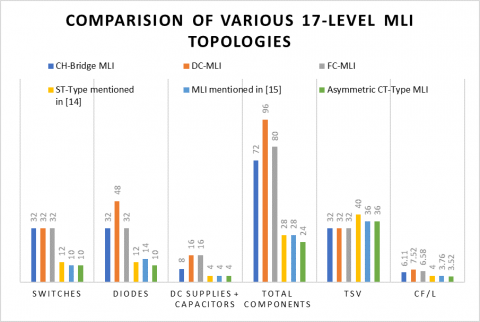
(i) Fewer number of components – On comparison of CT-Type MLI with the conventional topologies [12-15], the CT-Type MLI boasts of its higher-level output in comparison to other topologies with a given number of switches. This is presented in Figure 2 and Figure 3.
(ii) Cost effective- To measure the cost effectiveness of the CT-Type MLI, i.e., determination of cost factor (C.F.) is done using Eq. (1) [23].
C.F. $=\mathrm{N}_{\mathrm{S}}+\mathrm{N}_{\mathrm{D}}+\mathrm{N}_{\mathrm{C}}+\mathrm{N}_{\mathrm{DC}}+\alpha \mathrm{TSV}_{\text {P.U. }}$ (1)
Here, NS, ND, NDC, NC represents number of switches, number of diodes, number of DC supplies and capacitor count respectively. TSV is total standing voltage while α is weight coefficient.
$\mathrm{TSV}_{\text {p.u. }}=\frac{\mathrm{V}_{\mathrm{TSV}}}{\mathrm{V}_{\mathrm{O}_{-} \max }}$ (2)
VO_max represents the maximum output voltage of MLI while VTSV is TSV*VDC, where VDC is the sum of all input DC voltages.
Figure 2. Comparison of various MLIs for generation of 9-level output
Figure 3. Comparison of various MLIs for generation of 17-level output
(iii) Efficiency – The CT-Type MLI's efficiency in both 9-level and 17-level configurations is compared to the efficiency of some other MLIs, as shown in Table 3 below. In terms of efficiency, the CT-Type MLI is substantially superior to other MLIs indicated in this table.
(iv) Separate polarity generation part not required- In most of the recently developed MLIs, the ‘level generation part’ generates only the positive voltage levels. To get a proper alternating voltage level, a separate ‘polarity generation part’ i.e., an additional H-bridge circuit is required as shown in Figure 4. This circuit ensures that the positive voltage levels appear across the output terminals when Sa & Sb are turned on while, the negative voltage levels appear across the output terminals when Sc & Sd are turned on. Thus, these two modes of operation of Sa & Sb and Sc & Sd ensures alternating voltage levels across the output. The CT-Type MLI does not require any ‘polarity generation portion’ to generate negative voltage levels.
Table 3. Comparison of various MLIs in terms of efficiency and output levels
|
Configuration |
Number of levels |
Efficiency |
|
MLI in [16] |
9 |
88% |
|
S3CM in [17] |
9 |
80.61% |
|
MLI in [18] |
9 |
93% |
|
ST-Type in [14] |
17 |
96.53% |
|
CT-Type MLI |
9, 17 |
98.29% |
Figure 4. Polarity generation module of MLIs
(v) Modularity – Another feature of the CT-Type MLI is that, due to its modular design, it may simply be connected in modules to enhance output voltage levels as needed. This is useful when solar panels are connected to the grid. For larger output levels, any ‘n' number of CT-Type MLIs can be coupled in both symmetrical and asymmetrical modes. Figure 5 depicts such a setup.
The output voltage will be provided across the Vo terminals, and by connecting more CT-Type modules to this setup, the output voltage can be adjusted to meet application requirements.
Figure 5. Modular extension using two modules of CT-Type MLI
The proposed system generates the three-phase voltage having 800 V as its peak value. It has a CT-Type MLI in asymmetric mode of operation (17-level output) taking DC power as input for feeding power to critical loads in islanded operation and also to grid for the case of peak load demand in grid connected operation. The system can be used for high voltage applications by increasing the input DC voltage values. The conventional three phase inverter requires one DC source as input while, the CT-Type MLI requires two DC sources per phase. This should not be a matter of concern considering the numerous other benefits the CT-Type MLI provides like less voltage stress across the switches, less filtering requirement because of high quality output, high voltage operability etc. The DC sources can be provided by solar PV, fuel cell, ESS (Energy Storage Systems) etc. Most of these sources are found in small compact sized structures, compared to large bulky Diesel-generator sets. So, these can be used as per requirement. Additionally, instead of using single type of source, hybrid DC sources can also be used. The analysis of the inverter is done for both islanded mode and grid connected mode.
Case a: Islanded mode-
In islanded mode of operation of the CT-Type MLI (Figure 6), the three phase CT-Type MLI generates a 17-level output voltage of peak value 800 V and it is being fed to a critical load. Here, a three phase RL load of arbitrary values R=100Ω and L= 1 mH per phase is used to demonstrate the critical load without the integration of the MLI with the utility grid. The critical loads can be any electrical load e.g., domestic lighting, motors or any life-saving medical instrument in hospitals. If we change the R and L values, the magnitude of the output current would change accordingly.
Figure 6. CT-Type MLI in islanded mode of operation
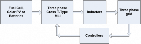
Case b: Grid connected mode-
There may be a practical situation when excess power is generated by the system due to the varying nature of the input DC sources to the MLI. The additional power can be stored in ESS or it can be fed to the grid. This mode can also be used for providing support to the grid in case of high peak load requirement.
In the grid connected mode of the three phase CT-Type MLI (Figure 7), the inverter is connected to the grid through a proper controller. The controller ensures synchronisation between the grid and the MLI. Also, the THD content of the injected current is maintained within the prescribed limits.
Figure 7. CT-Type MLI in grid connected mode of operation
Control Technique-
The ab-coordinate system is the projection of the three phase sinusoidal quantities onto a stationary two-axis reference frame. The corresponding ab-quantities are AC quantities while, the dq- coordinate system is the projection of the three phase sinusoidal quantities onto a rotating two-axis reference frame, rotating with the same angular velocity as the sinusoidal phase quantities. The corresponding dq-quantities are DC quantities.
We require these transformations because tracking non-DC quantities with PID controllers is erroneous. Secondly, use of dq-coordinate system instead of corresponding abc-coordinate system requires only two PID controllers. The Clarke (abc to ab) and the Park (ab to dq) transformations are used to convert these quantities from one reference frame to other.
The control mechanism of the inverter in grid connected mode is shown here. First, the three-phase grid voltage is sensed and converted into corresponding ‘ab-coordinates’ which are further converted into ‘dq-coordinates’ (Figure 8). The ‘Vq’ part obtained is then compared with a reference value and the error is passed through the PI controller to obtain the value of ‘δ’. This mechanism is known as PLL (Phase Locked Loop).
Figure 8. PLL
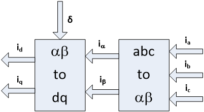
Figure 9. Conversion of three phase grid current to dq-coordinates
Figure 10. Generation of gate pulses for CT-Type MLI in grid connected mode using ‘iref’.
In the next step, the three-phase grid current are transformed first into ab and then to dq-coordinate systems using the value of ‘δ’ from the PLL (Figure 9). These ‘dq-axis’ currents are then compared with some reference values and the errors are passed through the PI controllers. The outputs of the PI-controllers are transformed into ab-coordinate systems using ‘δ’ and then these values are again transformed into the three phase reference voltages to generate suitable PWM pulses for the CT-Type MLI (Figure 10).
The reference value of ‘id’ i.e., ‘iref’ in Figure 10 is set to be equal to ‘impp’ as per the current supplying capability of the Fuel Cell, Solar PV or the batteries.
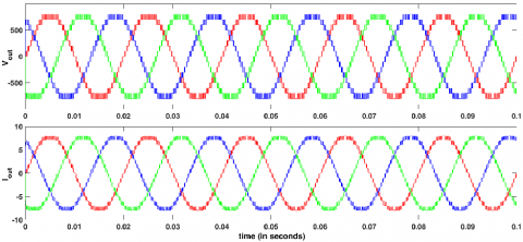
The output of the CT-Type MLI is obtained in the asymmetric mode to obtain 17-level voltage waveforms. For this, the input DC voltages fed to the MLI are VL= 200 V and VR = 600 V. This 17-level output voltage is fed to the three-phase critical load of R=100Ω and L= 1 mH per phase. The corresponding output voltage and current waveforms are shown in Figure 11 (a) while Figure 11 (b) depicts the FFT analysis of the load current. The current waveform in islanded mode has THD of 5.95% which can be further decreased by the use of proper filtering technique.
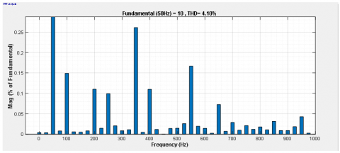
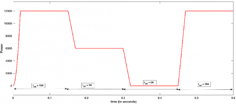
In the grid connected mode of operation of the CT-Type MLI, the power obtained from the MLI is injected to the grid with the help of controller described in the previous section. The corresponding three phase grid voltage and current waveforms are shown in Figure 12 (a). The value of reference current ‘iref’ is set to be equal to 10 A from time 0 to 0.15 seconds, 5 A from time 0.15 to 0.3 seconds, 0 A from time 0.3 to 0.45 seconds and again 10 A from time 0.45 to 0.6 seconds. The control system is successfully controlling the injected currents in the grid as per these reference values. The corresponding power fed to the grid is also changing its values as per these variations (Figure 12 (c)). The FFT analysis of the injected current is depicted in Figure 12 (b). These output results are summarized in Table 4.
The IEEE 519 standard establishes voltage and current harmonics distortion standards for electrical system design. It sets the limit of maximum permissible THD to 5% for the case of any current injected into the grid. In our case the THD for injected current is 4.10%, which is allowed as per the IEEE standards.
(a) Output voltage and load current waveforms
(b) FFT analysis of output current
Figure 11. CT-Type MLI in islanded mode
(a) Output voltage and injected current waveforms
(b) FFT analysis of output current
(c) Power fed into the grid
Figure 12. CT-Type MLI in grid connected mode (with proper inductor filter)
The above results suggest that the three phase CT-Type MLI can transform the power from solar PV, fuel cell or batteries into AC power which can be used for the critical load application in case of emergency situations or the AC power can be fed to the grid successfully. The additional merit of such system is that the CT-Type MLI can use power from solar, wind and fuel cell simultaneously unlike three phase conventional two level inverter.
Table 4. Output results for the overall system
|
Descriptions |
Asymmetric operation |
|
|
Voltage input to the MLI |
VL= 200V, VR = 600 V |
|
|
Islanded mode |
Output of MLI (peak-value) |
Vo = 800 V |
|
Io = 8 A |
||
|
THD in output current |
5.95% |
|
|
Grid connected mode |
Output of MLI (peak-value) |
Vo = 800 V |
|
Io = 10 A, 5A and 0 A as per iref |
||
|
THD in injected current |
4.10% |
|
|
Switching frequency |
15 KHz |
|
|
Fundamental frequency |
50 Hz |
|
In this paper, the recently developed CT-Type MLI is thoroughly examined in terms of various parameters like device count, cost factor per level, TSV etc and its superiority to traditional and many recent inverters is discovered.
This paper's main contributions are:
The CT-Type MLI, outperforms traditional inverters in terms of output waveform quality and helps to reduce the number of switches.
It's also worth noting that this topology doesn't require any additional H-bridges for polarity generation helped to reduce the number of switches, lowering the complexity and expense.
The single stage renewable energy-based system eliminates the use of additional DC-DC converter thereby decreasing cost and complexity in the circuit and enhancing efficiency of the overall system.
The inverter’s output waveforms satisfy IEEE519 harmonic standards in both islanded mode and grid connected operation.
In the grid integration mode, the control mechanism is able to maintain the grid synchronisation when tested under varying reference current. This would be beneficial when the load is of varying nature.
Thus, the application of the CT-Type MLI for renewable energy applications in supplying power to critical loads, microgrids and grid integration is attained.
|
MLI |
Multilevel Inverter |
|
THD |
Total Harmonic Distortion |
|
TSV |
Total Standing Voltage |
|
CHB |
Cascaded H-Bridge |
|
FC |
Flying Capacitor |
|
NPC |
Neutral Point Clamped |
[1] Gopal, Y., Birla, D., Lalwani, M. (2020). Reduced switches multilevel inverter integration with boost converters in photovoltaic system. SN Appl. Sci., 2(1): 1-15. https://doi.org/10.1007/s42452-019-1848-7
[2] Jagabar, J.S., Krishnaswamy, V. (2018). An assessment of recent multilevel inverter topologies with reduced power electronics components for renewable applications. Renew. Sustain. Energy Rev., 82: 3379-3399. https://doi.org/10.1016/j.rser.2017.10.052
[3] Rashid, M. (2014). Power Electronics: Circuits, Devices and Applications, 3rd ed. Pearson, 2014.
[4] Franquelo, L.G., Rodriguez, J., Leon, J.I., Kouro, S., Portillo, R., Prats, M.A.M. (2008). The age of multilevel converters arrives. IEEE Ind. Electron. Mag., 2(2): 28-39. https://doi.org/10.1109/MIE.2008.923519
[5] Liang, X., Andalib-Bin-Karim, C. (2018). Harmonics and mitigation techniques through advanced control in grid-connected renewable energy sources: A review. IEEE Trans. Ind. Appl., 54(4): 3100-3111. https://doi.org/10.1109/TIA.2018.2823680
[6] Wu, B. (2006). High-Power Converters and AC Drives, 1st ed. New Jersey: Wiley-IEEE Press.
[7] Sun, X., Wang, B., Zhou, Y., Wang, W., Du, H., Lu, Z. (2016). A single dc source cascaded seven-level inverter integrating switched-capacitor techniques. IEEE Trans. Ind. Electron., 63(11): 7184-7194. https://doi.org/10.1109/TIE.2016.2557317
[8] Jing, H., Corzine, K.A. (2006). Extended operation of flying capacitor multilevel inverters. IEEE Trans. Power Electron., 21(1): 140-147. https://doi.org/10.1109/TPEL.2005.861108
[9] Rodriguez, J., Member, S., Bernet, S., Steimer, P.K., Lizama, I.E. (2010). A survey on neutral-point-clamped inverters. IEEE, 57(7): 2219-2230. https://doi.org/10.1109/TIE.2009.2032430
[10] Alishah, R.S., Hosseini, S.H., Babaei, E., Sabahi, M., Gharehpetian, G.B. (2017). New high step-up multilevel converter topology with self-voltage balancing ability and its optimization analysis. IEEE Trans. Ind. Electron., 64(9): 7060-7070. https://doi.org/10.1109/TIE.2017.2688968
[11] Daula Siddique, M., Mekhilef, S., Padmanaban, S., Memon, M.A., Kumar, C. (2020). Single phase step-up switched-capacitor based multilevel inverter topology with SHEPWM. IEEE Trans. Ind. Appl., 9994: 1. https://doi.org/10.1109/tia.2020.3002182
[12] Nair, V.R., Rahul, A.S., Kaarthik, R.S., Kshirsagar, A., Gopakumar, K. (2017). Generation of higher number of voltage levels by stacking inverters of lower multilevel structures with low voltage devices for drives. IEEE Trans. Power Electron., 32(1): 52-59. https://doi.org/10.1109/TPEL.2016.2528286
[13] Edwin Jose, S., Titus, S. (2017). A stipulation based sources insertion multilevel inverter (SBSIMLI) for waning the component count and separate DC sources. J. Electr. Eng. Technol., 12(4): 1519-1528. https://doi.org/10.5370/JEET.2017.12.4.1519
[14] Samadaei, E., Sheikholeslami, A., Gholamian, S.A., Adabi, J. (2018). A square T-Type (ST-Type) module for asymmetrical multilevel inverters. IEEE Trans. Power Electron., 33(2): 987-996. https://doi.org/10.1109/TPEL.2017.2675381
[15] Babaei, E., Gowgani, S.S. (2014). Hybrid multilevel inverter using switched capacitor units. IEEE Trans. Ind. Electron., 61(9): 4614-4621. https://doi.org/10.1109/TIE.2013.2290769
[16] Zamiri, E., Vosoughi, N., Hosseini, S.H., Barzegarkhoo, R., Sabahi, M. (2016). A new cascaded switched-capacitor multilevel inverter based on improved series-parallel conversion with less number of components. IEEE Trans. Ind. Electron., 63(6): 3582-3594. https://doi.org/10.1109/TIE.2016.2529563
[17] Lee, S.S. (2018). Single-stage switched-capacitor module (S3CM) topology for cascaded multilevel inverter. IEEE Trans. Power Electron., 33(10): 8204-8207. https://doi.org/10.1109/TPEL.2018.2805685
[18] Liu, J., Lin, W., Wu, J., Zeng, J. (2019). A novel nine-level quadruple boost inverter with inductive-load ability. IEEE Trans. Power Electron., 34(5): 4014-4018. https://doi.org/10.1109/TPEL.2018.2873188
[19] Karthik, A., Loganathan, U. (2020). A reduced component count five-level inverter topology for high reliability electric drives. IEEE Trans. Power Electron., 35(1): 725-732. https://doi.org/10.1109/TPEL.2019.2913821
[20] Tian, H., Li, Y., Li, Y.W. (2018). A novel seven-level hybrid-clamped (HC) topology for medium-voltage motor drives. IEEE Trans. Power Electron., 33(7): 5543-5547. https://doi.org/10.1109/TPEL.2017.2780058
[21] Meraj, S.T., Hasan, K., Masaoud, A. (2020). A novel configuration of cross-switched T-Type (CT-Type) multilevel inverter. IEEE Trans. Power Electron., 35(4): 3688-3696. https://doi.org/10.1109/TPEL.2019.2935612
[22] Raj, S., Mandal, R.K., De, M. (2021). Analysis of cross T-Type MLI using different modulation schemes. J. Inst. Eng. Ser. B. https://doi.org/10.1007/s40031-021-00646-x
[23] Dhanamjayulu, C., Prasad, D., Sanjeevikumar, P., Maroti, P.K., Holm-Nielsen, J.B., Blaabjerg, F. (2021). Design and implementation of seventeen level inverter with reduced components. IEEE Access, vol. 9. https://doi.org/10.1109/ACCESS.2021.3054001