Oussama Gherouat* | Abdelouahab Hassam | Oualid Aissa | Badreddine Babes
© 2021 IIETA. This article is published by IIETA and is licensed under the CC BY 4.0 license (http://creativecommons.org/licenses/by/4.0/).
OPEN ACCESS
In this paper, a synergetic approach based on particle swarm optimization (SC-PSO) technique is proposed for Single-Phase Shunt Active Power Filter (SP-SAPF). Two-loop cascade controller for SP-SAPF has been designed. In the first loop, a PI controller is used to effectively regulate the DC link voltage. In the second one, a synergetic controller is performed in the current compensation control loop. The various adjustable parameters of the studied synergetic controller are tuned by a PSO algorithm. The objective of this adjustment is to get the optimal control parameters for satisfying requirements of power quality and high dynamic responses for SP-SAPF. The effectiveness of the suggested SC-PSO approach has been proved by simulation and experimental tests using MATLAB/Simulink environment and dSPACE 1104 card for several operating conditions. The experimental results demonstrate that the developed SC-PSO approach is very satisfactory and offers a high performance for both transient and steady states.
single phase, shunt active power filter, synergetic control, particle swarm optimization, PI controller, dSPACE card 1104
Nowadays, Single-Phase Pulse Width Modulation (SP-PWM) inverter-based Shunt Active Power Filter (SAPF) plays a vitally important role to generate the required harmonic components to minimize harmonic distortion currents and compensate reactive power in low or medium voltage distribution networks [1]. Single-Phase SAPFs (SP-SAPFs) are characterized by simple control design, small size, high energy efficiency, stable output voltage, improved safety, energy security and great ability to adapt with various forms of linear and non-linear loads. Moreover, the standard SP-SAPFs do not need high-voltage components that are typically required in specially designed three-phase SAPFs [2-5]. Figure 1. presents the schematic diagram of the typical SP-SAPF system. The latter is the subject of many researches over the recent years [6, 7].
These SAPF systems can be used not only as Static Var Generators (SVGs) to stabilize and improve the voltage profile in power systems, but also to compensate the harmonic contents, reactive power and unbalanced load current with a fast-dynamic behavior and flexibility during load variations [6, 8, 9]. One of the key factors for the establishment of the SP-SAPF system is the control mechanism. Faced with the variability over time of SP-SAPF systems, conventional deterministic strategies are not sufficiently resistant to ensure better performance required at the same time in the dynamic and permanent conditions [10]. For the control of the DC link voltage and the harmonic current of SP-SAPF, voltage and current controllers of the Proportional-Integral (PI) type have been used. However, this kind of controller requires exact linear mathematical model of the SP-SAPF system, hardly achievable under nonlinearity, parameter variations, and load disturbances [11-13].
Hysteresis controllers have been introduced in the published works and generated a great deal of interest [14] in SP-SAPF applications [15, 16]. This type of controllers provides over-current protection capability for versatility and simplicity of practical implementation. To validate practically the hysteresis controller, the digital signal processor guarantees a good and fast dynamic response compared to other types of digital controllers [17]. Despite the excellent performance of the hysteresis controller, the latter suffers from the problem of the switching frequency which is variable and high. This phenomenon increases power losses and produces severe electromagnetic compatibility (EMC) noise in the single-phase APF and also complicates the selection of the coupling inductor in hysteresis current controllers [18].
To fix the switching frequency of SP-SAPF system, Wang et al. [19] have proposed an adaptive feed-forward control scheme that varied the hysteresis band in the hysteresis modulator in the event of any change of the current error. The adaptive hysteresis modulator is an efficient method for adjusting the switching frequency. The disadvantage of this modulator lies in the extra input voltage feedback which can lead to an increase in the total cost and the complexity of the employed control system. For these reasons, the adaptive hysteresis modulator is not suitable for SP-SAPF system. In their turn, Antchev et al. [20] have limited the switching frequency of SP-SAPF with calculation of any time interval while maintaining the switching action.
The finite control set model predictive control (FCS-MPC) scheme is suggested by Alhasheem et al. [21] for the harmonic current regulation of the SAPF system. The natural switching action of SP-SAPF is compatible with FCS-MPC feature. This strategy is well recognized for its stability, robustness, fast dynamic reaction, and good regulation properties in a wide range of operating conditions. Furthermore, this method does not require the use of internal current loops, PWM or SVPWM modulators for the control of the single phase APF. According to the FCS-MPC theory, the main objective of the SAPF control is to predict the behavior of this system for all admissible switching states over the prediction horizon in order to solve the optimization problem and guarantee the filter current regulation with low THD in different conditions. However, this control technique is more effective than the hysteresis controllers but its performances are dependent of the accurate prediction of the future behavior of the SAPF system [22]. Using incorrect parameters for the predictive controller may result in an inaccurate prediction of future behavior due to the incorrect system model. This situation can lead to the incorrect choice of switching states resulting in a deterioration of the performance of the applied control, even endangering the stability of the system. Building an exact system model with precise parameters is thus important to avoid these serious anomalies. To estimate the uncertain parameters, an FCS-MPC current control with model parameter mismatch and a fuzzy adaptive control law have been proposed for the governance of the SAPF system in the references of Young et al. [22] and Narongrit et al. [23]. However, it is not possible to estimate all uncertain parameters of the SP-SAPF system model [7].
The recently introduced synergistic control has been widely accepted by the control community as well as by the industrialists. The success of its implementation has been proven in several areas such as: the battery charging system where Eghtedarpour et al. [24] have used the synergetic approach for the local control of the power converters; the flexible satellites with a desired attitude achievement have been presented by Sabatini et al. [25]; the output voltage control of the DC/DC buck converter system with an approximation of the unknown parameters has been studied by Babes et al. [26] and Hamouda et al. [27]; the speed control of the PMDC motor has been proposed by Hamouda et al. [28]; the hydraulic turbine regulating system with a stable frequency for small and medium-size power stations has been treated by Huang et al. [29] and Bouchama et al. [30] present the design of power system stabilizers insensitive to parameters variation. The principle of the synergistic control strategy is similar to that of the sliding mode control (SMC) but devoid of the chattering problem. This robust approach is based on the concept of forcing a system under control to operate according to a preselected designer constraint. Based on a continuous control law and a macro-variable that can be a simple combination of state variables, synergistic control is more suitable to a real-time implementation. The main benefit of this approach is that once system states reach the attractor, the system dynamics remain insensitive to a class of parameter variation and external disturbances [30, 31]. Thanks to the high performance of the synergistic control technique, several research articles were published in the literature. However, in much of this research, the synergistic control law was designed based on an asymptotic stability analysis where the trajectories of the system evolve towards a specified attractor reaching equilibrium in an infinite time [31, 32]. This research work discusses the subject of power quality improvement by the SP-SAPF via the synergistic technique. The proposed controller has many advantages such as: ease of practical implementation; asymptotic stability ensured with respect to the required operating conditions; operation under a fixed switching frequency reducing the burden of the filtering device design as well as insurance of robustness characteristics of the SMC technique with low chattering [31]. These advantages offered by this advanced technique have a positive influence on the operation of SP-SAPF through rapid dynamics on the controlled quantities and effective compensation of harmonics, thus leading to a quality of energy recognized by international standards.
The proposed synergetic control algorithm is designed to master the switching states of the SAPF device is based on two gains T and λ imposed and identified by the experience of the designer. To properly determine the two aforementioned gains during the development of the synergistic controller, these latter will undergo an adjustment by the particle swarm optimization (PSO) algorithm. In order to effectively control the SP-SAPF system, two control loops must be governed. To do this and in addition to the application of the synergistic non-linear controller for the internal current control loop of the single-phase APF, another classical PI type controller has been reserved for calculating the reference current in the external loop of the DC bus voltage of SP-SAPF. This paper discusses the simulation by MATLAB/Simulink and the practical validation via the dSPACE 1104 card of the advanced SP-SAPF system which is based on a PI controller and Synergetic Control (SC) law optimized by PSO algorithm. The PI regulator ensures the control of the output voltage of the studied SP-SAPF on the one hand and the calculation of the reference current on the other hand. In turn, the role of the optimized synergistic strategy is to govern the switching states for the switches of the single-phase filtering device after application of the current command. The proposed control strategy has confirmed its superiority through the comparison of the simulation results of the latter with those of the classical strategy (classical PI and classical Hysteresis regulators) as well as of the classical synergistic not optimized method (classical PI and synergistic control law). In addition, the practical validation of the SP-SAPF based on the optimized synergetic control ensures a total harmonic distortion (THD) rate of the source current fully meeting the IEEE international standard. In the case of a healthy and distorted power source, a THD of 3.3% and of 5.3% have been recorded respectively. The obtained results are satisfactory and the objective of improving energy quality has largely been achieved.
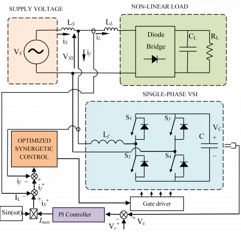
SP-SAPF system relies on four major parts: supply voltage (Vs), non-linear load, Single-Phase Voltage Source Inverter (SP-VSI) and controller block. The control unit consists of two controllers: the proposed SC-PSO controller for the current and the PI controller for the DC link voltage regulation. The interfacing inductor (Lf) is used to filter out the high frequency components in the filter current generated by the switching pulses of SP-VSI. The fundamental mission of the SP-SAPF system, is to inject the suitable current to compensate the power quality issues in supply voltage and to supply a part of load reactive power as illustrated in Figure 1.
The DC bus voltage of the APF is detected and compared with its imposed reference to have the maximum amplitude of the reference source current (Imax) after intervention of the PI regulator. The difference recorded between this current and the sensed current (IL) represents the filter current reference. The mastery of the APF switches is based on the optimized synergistic strategy where its input is identified by the difference between the filter current and its reference. The novelty provided by this control system consists in the use of the synergistic control law on the one hand and the optimization of its parameters by PSO on the other hand.
This paper is organized as follows: the description of the studied system is given in section 2; the proposed control approaches are presented in section 3; simulation and experimental validation results are discussed in sections 4 and 5 respectively; finally, a conclusion is given in section 6.
Figure 1. Description of proposed SP-SAPF system
3.1 DC link voltage regulator
PI controller is offered to decrease the instability and variations of the DC link voltage, such as indicated in Figure 1. The DC link voltage regulator consists of the proportional gain (Kp) for enhancing the rise time and the integral gain (Ki) for smooth operation, eliminating the error between the sensed DC link voltage (VC) and its reference (VC*) in steady state [33].
To calculate the PI controller's gains, firstly we must determine the transfer function of the studied system with PI controller through the Eq. (1) [34]:
$\frac{{{V}_{C}}}{V{{_{C}^{{}}}^{*}}}=\frac{\left( {{{K}_{P}}}/{C}\; \right)\left( s+{{{K}_{i}}}/{{{K}_{P}}}\; \right)}{s{}^\text{2}+\left( {{{K}_{P}}}/{C}\; \right)\cdot s+{{{K}_{i}}}/{C}\;}$ (1)
We notice from the Eq. (1) that the closed loop system is presented by a canonical second order transfer function.
$\frac{{{V}_{C}}}{V_{C}^{*}}=\frac{\omega {}^\text{2}}{s{}^\text{2}+2\xi {{\omega }_{n}}\cdot s+\omega _{n}^{2}}$ (2)
Through the equalization of the two denominators of Eqns. (1) and (2), the controller's gains (Kp and Ki) are quantified as follows:
$\left\{ \begin{align} & {{\text{K}}_{\text{P}}}\text{=2 }\!\!\xi\!\!\text{ }{{\text{ }\!\!\omega\!\!\text{ }}_{\text{n}}}\text{C} \\ & {{\text{K}}_{\text{i}}}\text{=C}{{\text{ }\!\!\omega\!\!\text{ }}_{\text{n}}}\text{ }\!\!{}^\text{2}\!\!\text{ } \\\end{align} \right.$ (3)
3.2 Design of synergetic control law
The basic procedure of synergetic control synthesis for SAPF is shown below. The choice of function of the system state variables (macro-variable) is the first step to design the synergetic controller’s synthesis as shown in Eq. (4).
$\psi =\psi (x,t)$ (4)
The main focus of the controller requires the system to have the attractor ψ=0. The characteristics of the macro-variable according to performance and control specifications can be selected by the designer. Also, the desired dynamic evolution of the macro variable is usually chosen by the Eq. (5).
$T\frac{d\psi }{dt}+\psi =0{{,}^{{}}}{{^{{}}}^{{}}}T>0$ (5)
T is a positive constant to be imposed by the designer. In our paper, its value is optimized by PSO algorithm.
The designer chooses speed convergence to the target equilibrium point. Eq. (6) is given by the chain rule of differentiation as follows:
$\frac{d\psi }{dt}=\frac{\partial \psi (x,t)}{\partial x}\frac{dx(t)}{dx}$ (6)
Making deference between the macro-variable Eq. (4) and Eq. (5) leads to Eq. (7).
$T\frac{\partial \psi (x,t)}{\partial x}f(x,U,t)+\psi (x,t)=0$ (7)
The law of the proposed SC can be found by solving Eq. (7) as follows.
${{U}_{SC}}={{U}_{d}}(x,t,\psi (x,t),T)$ (8)
The differential equations form of nonlinear dynamic for SP-SAPF system is given by the Eq. (9).
$\left\{ \begin{align} & {{{\dot{x}}}_{1}}=\frac{-1}{{{L}_{f}}}{{x}_{2}}(1-2{{U}_{d}})+\frac{{{V}_{SS}}}{{{L}_{f}}} \\ & {{{\dot{x}}}_{2}}=\frac{1}{C}{{x}_{1}}(1-2{{U}_{d}}) \\\end{align} \right.$ (9)
As reminder: x(t) represents the state coordinate; x1 represents the current filter (if); x2 represents the DC link voltage (VC); Ud is the control input (the duty ratio); Lfis the inductor of SP-SAPF and C is the capacitor of the DC link voltage.
The synergetic control synthesis of the system that we have presented in Eq. (9) started by demonstrating a designer that is been chosen as macro-variable and given in Eq. (10).
$\psi ={{e}_{if}}+\lambda \int{{{e}_{if}}}=({{x}_{1}}-x_{1}^{*})+\lambda \int{({{x}_{1}}-x_{1}^{*})dx(t)}$ (10)
$\begin{align} & \dot{\psi }={{{\dot{e}}}_{if}}+\lambda {{e}_{if}} \\ & \dot{\psi }=\left[ \frac{1}{{{L}_{f}}}{{x}_{2}}(2\,{{U}_{d}}-1)+\frac{{{V}_{ss}}}{{{L}_{f}}}-\dot{x}_{1}^{*} \right]+\lambda ({{x}_{1}}-x_{1}^{*}) \\\end{align}$ (11)
Moreover, having Eq. (5) and Eq. (11), the resulting control law Ud is given by Eq. (13):
$T\left[ \frac{1}{{{L}_{f}}}{{x}_{2}}(2\,{{U}_{d}}-1)+\frac{{{V}_{ss}}}{{{L}_{f}}}-\dot{x}_{1}^{*} \right]+T.\lambda ({{x}_{1}}-x_{1}^{*})+\psi =0$ (12)
$U_{S C}=U_{d}=\frac{\frac{\psi}{\mathrm{T}}+\lambda\left(x_{i f}-x_{i f}^{*}\right)-x_{i f}^{*}+\frac{1}{L_{f}} V_{s s}}{\frac{2}{L_{f}} x_{2}}+\frac{1}{2}$ (13)
To confirm stability, we use the following Lyapunov function candidate:
$V=\frac{1}{2}{{\psi }^{T}}\psi $ (14)
Therefore:
$\dot{V}={{\psi }^{T}}\dot{\psi }$ (15)
The use of Eq. (16) leads to:
$\dot{V}=-\frac{1}{\mathrm{~T}}\left(e_{i f}+\lambda \int e_{i f}\right)^{2}$ (16)
Form Eq. (16) it can be found that $\dot{V}<0$.
On the basis of Lyapunov theory, the stability of the SP-SAPF system is assured via the synergetic control law.
3.3 Implementation of PSO for Synergetic controller (SC-PSO)
3.3.1 Formulation of the problem to be optimized
The formulation of the problem to be optimized is mainly concerned with minimizing the error ERR = if – if* where the objective function F(X) can be written as fellow:
$Min~F(x)=Min(ERR)$ (17)
With: X the control parameter set which can be written in the following form:
$X=\left[ T,\text{ }\!\!\lambda\!\!\text{ } \right]$ (18)
The objective function is subjected to inequality constraints as shown below:
$\begin{align} & {{T}^{\min }}<\text{T}<{{T}^{\max }} \\ & {{\text{ }\!\!\lambda\!\!\text{ }}^{\min }}<\text{ }\!\!\lambda\!\!\text{ }<{{\text{ }\!\!\lambda\!\!\text{ }}^{\max }} \\\end{align}$ (19)
3.3.2 Particle swarm optimization
J. Kennedy & R. Eberhart have been proposed the PSO algorithm in 1995 [35]. It is one of the stochastic search algorithms. In PSO, the population is made up of solution candidates named particles [36, 37].
Each particle having a position ${{X}_{i}}=(x_{i}^{1},x_{i}^{2},...,x_{i}^{l})$ and a flight velocity ${{V}_{i}}=(v_{i}^{1},v_{i}^{2},...,v_{i}^{l})$. In fact, every particle has a best position $P_{ibest}^{{}}=(P_{ibest}^{1},P_{ibest}^{2},...,P_{ibest}^{l})$ and a global best position $G_{best}^{{}}=(G_{best}^{1},G_{best}^{2},...,G_{best}^{l}).$
The update of position and velocity is obtained by the following equations:
$X_{r}^{iter+1}=X_{r}^{iter}+\theta \times V_{r}^{iter+1}$ (20)
$\begin{align} & V_{r}^{iter+1}=\theta \times {{w}_{{}}}.V_{r}^{iter+1}+{{\theta }_{1}}.rand1.(P_{best}^{iter}-X_{r}^{iter})+ \\ & {{\theta }_{2}}.rand2.(G_{best}^{iter}-X_{r}^{iter}) \\\end{align}$ (21)
where: w represents the inertia weight factor; θ1 and θ2 are the acceleration factors; rand is a uniform random value between [0,1]; Viter and Xiter denote the velocity and the position of one particle i at iteration k, respectively.
The acceleration coefficients are considered as fixed values as follow: θ1=θ2=2.05 [38].
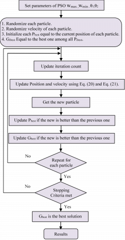
Figure 2. Flowchart of SC strategy optimised by PSO
The main optimization steps of the SC-PSO strategy are illustrated on the flowchart illustrated by Figure 2.
PSO based SC approach is applied to adjust the optimal control variables in order to minimize the ERR while satisfying a good control of the switching states of the SP-SAPF inverter switches.
The performance of the proposed SP-SAPF system based on SC strategy optimised by PSO has been evaluated by using MATLAB/Simulink software. The nominal values for SP-SAPF system parameters and components are listed in Table 1.
The obtained simulation results are ranging from 3 to 7. Figure 3 shows both source voltage (VS), source current (iS), load current (iL) and the filter current (if). The source current is presented by a sinusoidal shape and in phase with the input voltage of the single-phase network. In their turn, both line and filter currents have been presented by their appropriate waveforms.
Figure 3. SP-SAPF performance waveforms under nonlinear load
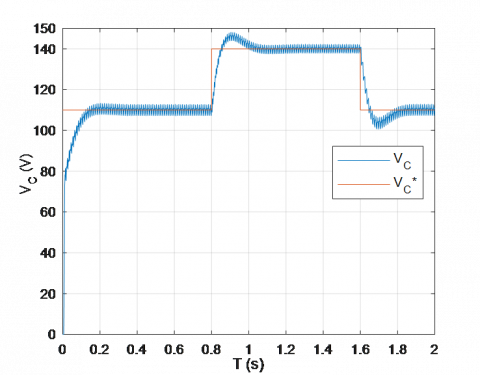
Figure 4. Simulation results of the output voltage (VC) under change of voltage references (VC*)
Figure 4 shows the performance of the DC link voltage under the conventional PI controller used during start-up as well as its progression towards the imposed reference voltage. The sensed output voltage (VC) correctly reaches its reference values (VC*) of: 110V, 140V and 110V in a very satisfactory manner.
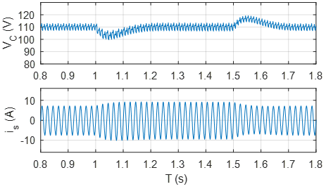
To show the robustness of the suggested SC-PSO approach, the DC link voltage is fixed to 110V and the nonlinear load underwent a modification in t1 = 1s by the addition of the resistance R = 23Ω in parallel with the old load then its elimination in t2 = 1.5s. The DC link voltage (VC) and the source current (iS) react correctly to these imposed operating conditions as shown in Figure 5.
Figure 5. Simulation results of DC link voltage (VC) and source current (is) during the change of the load
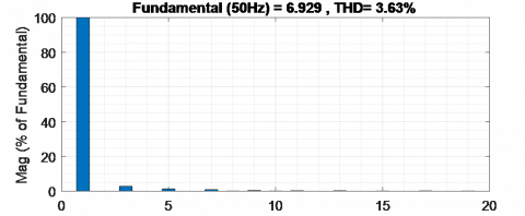
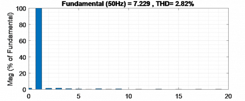
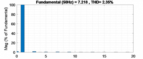
A comparative simulation study between the classical hysteresis control, the synergistic and optimized synergistic approach applied to the single-phase filter have been established in order to evaluate the quality of the source current (is) as shown in Figure 6. The spectral analysis of these source currents has been presented in Figure 7.
It is clearly visible that in the absence of the parallel active filter, a THD of 49.07% was recorded. After activation of the parallel active filter controlled by the three techniques mentioned previously, new THD values were recorded which are respectively equal to: 3.63%, 2.82% and 2.35%. Through these results, the optimized synergistic control strategy of the SP-SAPF system clearly marked its superiority compared to other conventional hysteresis and non-optimized synergistic techniques.
Figure 6. Compared waveforms of the source current (is)
Table 1. Parameters of the studied system
|
Parameters |
Symbol |
Values |
|
System frequency |
fs |
50 Hz |
|
Source voltage |
VS |
50V |
|
Input inductance |
LS |
4mH |
|
Load inductance |
LL |
2mH |
|
Load resistance |
RL |
11.5Ω |
|
Load capacitor |
CL |
550µF |
|
Filter inductance |
Lf |
8mH |
|
Filter capacitor |
C |
1100µF |
|
Voltage reference |
VC* |
110V |
(a)
(b)
(c)
(d)
Figure 7. Source current spectral analysis: (a) without SAPF, (b) with Hysteresis control, (c) with SC method and (d) with the proposed SC-PSO method
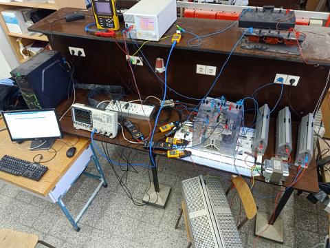
To give more confidence to our study, an experimental test bench is carried out using a dSPACE 1104 board as presented in Figure 8. The performance of considered synergetic approach based on PSO algorithm and PI controller for the SP-SAPF has been tested for several conditions. For assess the studied control strategy, our SP-SAPF system is experienced in transient and steady states.
Furthermore, coverage of changes affecting the nonlinear load, the DC link voltage (VC) and the power source (VS) has been taken into consideration in this section. Using the power quality analyzer (Chauvin ArnouxC.A.8335) and the digital oscilloscope (GwinstekGDS-3504), the obtained practical results are recorded and presented in the following sections.
Figure 8. Photograph of platform of the experiment test
5.1 SP-SAPF performance in transient and steady states
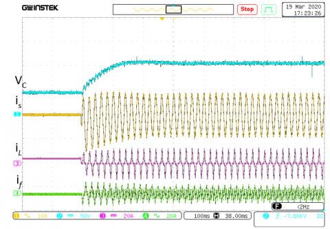
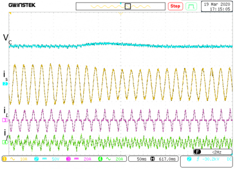
The start transient of the SP-SAPF at the reference point of DC link voltage VC* of 110V accompanied by the currents is, iL and if responds smoothly without overshooting as shown in Figure 9.
Figure 9. Transient response of SP-SAPF during increment of DC link voltage from VC=0V to VC=110V
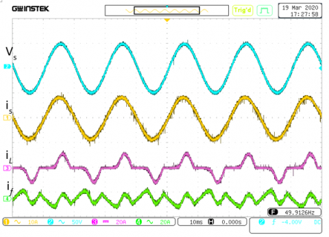
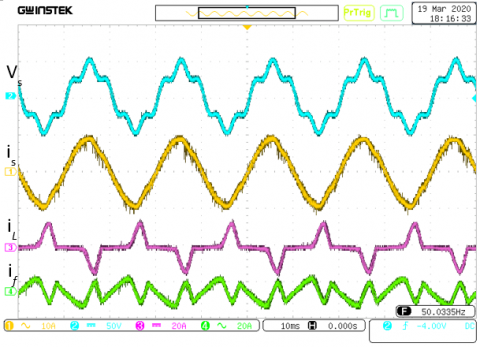
Figure 10 shows the steady-state responses of the suggested control law under non-linear RC load. The source current has a nearly perfect waveform sine and in phase with the supply voltage thanks to the filter current. For its part, the load current is presented in steady state by its usual form.
Figure 10. Steady-state performance of the proposed control of the SP-SAPF under a nonlinear RC load condition
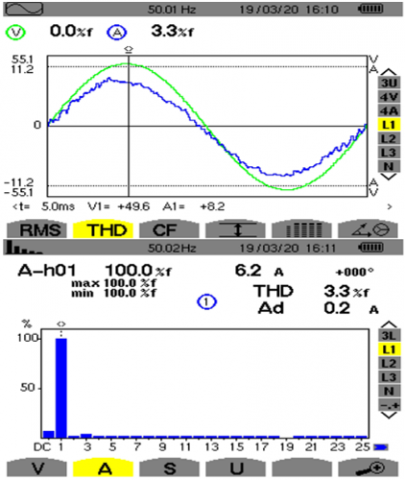
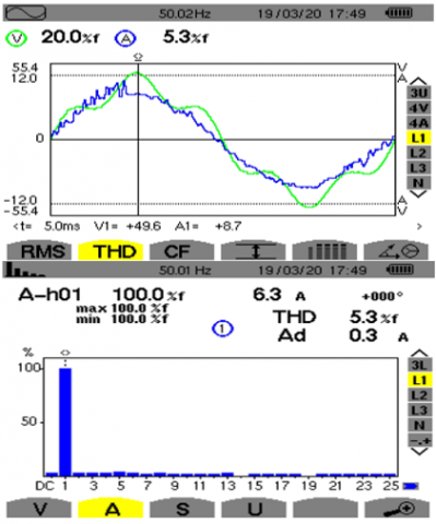
Before connecting and commissioning the SP-SAPF, the source current is distorted and its THD is rated at 38% as shown in Figure 11.
Figure 11. Power quality analysis of is without SP-SAPF
Figure 12. Power quality analysis of is with SP-SAPF controlled by SC-PSO strategy
After activation of SP-SAPF controlled by the synergistic strategy optimized by PSO, the source current has become sinusoidal in phase with the source voltage and its THD is 3.3% as shown in Figure 12.
5.2 Performance of the SP-SAPF during change in the DC link voltage reference
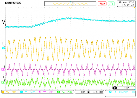
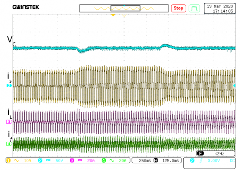
The variation of the DC link reference voltage for the following values 110V, 140V and 110V was used to verify the performance of the SP-SAPF as shown in Figure 13. The DC voltage of the filter quickly reaches and easily follows the various imposed references with recording of acceptable overshoots. In addition, the source, load and filter currents maintained their appropriate values during the changes made in the DC link voltage.
Figure 13. Dynamic response of the proposed control of the SP-SAPF under the DC voltage reference sudden change from 110V to 140V and inversely
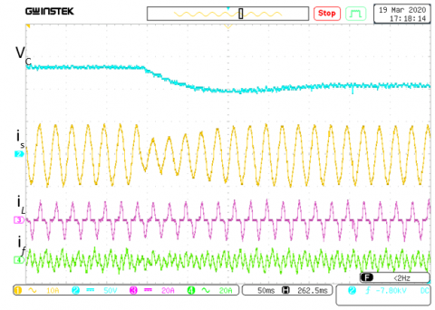
5.3 Performance of the SP-SAPF during change in the nonlinear load
A nonlinear load change is implemented by connecting/disconnecting an additional load in parallel of the old load. The real-time test results are shown in Figure 14. Because of step change in nonlinear load, source current increases/decreases smoothly. DC link voltage remains fairly constant and does not experience the variations in nonlinear load. With the exception of certain distortions due to the change in the source current, the DC link voltage is maintained at a constant value of 110 V during the change in the nonlinear load. The load and filter currents react correctly to this established test.
Figure 14. Dynamic response of the SP-SAPF under a nonlinear load variation
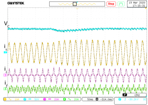
5.4 Performance of the SP-SAPF under a polluted power source
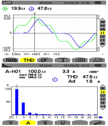
In this section, the aim is to prove the robustness of the proposed optimized synergetic control in case of a polluted power source with a THD of 20%. The obtained practical results in steady state of the source, load and filter currents are given in Figure 15. Without SP-SAPF of the deformed power source, the THD of the measured source current is equal to 47.6% as indicated in Figure 16. In the event that the SP-SAPF is activated and the power source is deformed, the saved THD in Figure 17 of the source current is 5.3%. This experience has proved the ability of SC-PSO control law to enhance the shape form current in case of the degraded quality of the power source [39].
Figure 15. Steady-state performance of the proposed control of the SP-SAPF under distorted source voltage condition
Figure 16. Power quality analysis without SP-SAPF under distorted source voltage condition
Figure 17. Power quality analysis of is with SP-SAPF controlled by SC-PSO strategy under distorted source voltage condition
This paper presents the simulation and experimental validation of the single-phase shunt active filter control strategy based on the synergistic technique optimized by the PSO algorithm. The two parameters T and λ which previously were imposed arbitrarily by the designer are this time determined by the PSO. The proposed command was able to effectively control the DC bus voltage as well as the current of the single-phase source through the better mastery of the filtering device switches. The evaluation of the optimized synergistic control was performed by MATLAB/Simulink software and practically confirmed by the dSPACE 1104 card.
The simulation in the case of the application of the optimized synergistic technique allowed us to have a better waveform of the source current (THD = 2.35%) compared to the quality of the currents obtained when using the classical hysteresis method (THD = 3.63%) and the non-optimized synergistic control (THD = 2.82%). These simulation results show the positive impact of the optimized synergistic control on the power quality of the single-phase source feeding the non-linear load.
The feasibility of the command developed was confirmed in practice by the dSPACE 1104 card under different operating modes of the SP-SAPF affecting the DC link voltage reference, the non-linear load and the quality of the single-phase electrical network. The optimized synergistic control has confirmed its success through the obtained practical results. The recorded source current is sinusoidal and in phase with the input voltage with a THD of 3.3% for an unpolluted voltage source. In the case of a polluted voltage source, a source current THD of 5.3% is saved. These practical results largely meet the international standard of the IEEE.
Finally, the strategy of optimized synergistic control applied to the single-phase filtering system can effectively contribute to improving the quality of energy in the tertiary sector.
[1] Rahmani, S., Al-Haddad, K., Kanaan, H.Y. (2008). Two PWM techniques for single-phase shunt active power filters employing a direct current control strategy. IET Power Electronics, 1(3): 376. https://doi.org/10.1049/iet-pel:20070253
[2] Lu, D.D.C., Iu, H.H.C., Pjevalica, V. (2007). A Single-Stage AC/DC converter with high power factor, regulated bus voltage and output voltage. IECON 2007. 33rd Annual Conference of the IEEE Industrial Electronics, pp. 1455-1460. https://doi.org/10.1109/iecon.2007.4459911
[3] Afghoul, H., Krim, F., Beddar, A., Babes, B. (2018). Real-time implementation of robust controller for PV emulator supplied shunt active power filter. 2018 6th International Renewable and Sustainable Energy Conference (IRSEC), pp. 1-6. https://doi.org/10.1109/irsec.2018.8703010
[4] Ferhat, M., Rahmani, L., Babes, B. (2019). DSP-based implementation of improved deadbeat control for three-phase shunt active power filters. Journal of Power Electronics, 20(1): 188-197. https://doi.org/10.1007/s43236-019-00029-y
[5] Hamouda, N., Babes, B., Kahla, S., Soufi, Y. (2019). Real time implementation of grid connected wind energy systems: predictive current controller. 2019 1st International Conference on Sustainable Renewable Energy Systems and Applications (ICSRESA). https://doi.org/10.1109/icsresa49121.2019.9182526
[6] Komurcugil, H., Kukrer, O. (2006). A new control strategy for single-phase shunt active power filters using a Lyapunov function. IEEE Transactions on Industrial Electronics, 53(1): 305-312. https://doi.org/10.1109/tie.2005.862218
[7] Salimi, M., Soltani, J., Zakipour, A. (2017). Experimental design of the adaptive backstepping control technique for single-phase shunt active power filters. IET Power Electronics, 10(8): 911-918. https://doi.org/10.1049/iet-pel.2016.0366
[8] Etxeberria-Otadui, I., Lopez De Heredia, A., Gaztanaga, H., Bacha, S., Reyero, M.R. (2006). A single synchronous frame hybrid (SSFH) multi frequency controller for power active filters. IEEE Transactions on Industrial Electronics, 53(5): 1640-1648. https://doi.org/10.1109/tie.2006.881994
[9] Routimo, M., Salo, M., Tuusa, H. (2005). Current sensorless control of a voltage-source active power filter. Twentieth Annual IEEE Applied Power Electronics Conference and Exposition. https://doi.org/10.1109/apec.2005.1453269
[10] Fang, H.J., Yang, R.F., Yu, Y.N., Xu, D.G. (2012). A study on the DC voltage control techniques of cascaded multilevel APF. Proceedings of the 7th International Power Electronics and Motion Control Conference. https://doi.org/10.1109/ipemc.2012.6259294
[11] Patnaik, S.S., Panda, A.K. (2013). Real-time performance analysis and comparison of various control schemes for particle swarm optimization-based shunt active power filters. International Journal of Electrical Power & Energy Systems, 52: 185-197. https://doi.org/10.1016/j.ijepes.2013.03.014
[12] Alhasheem, M., Mattavelli, P., Davari, P. (2020). Harmonics mitigation and non-ideal voltage compensation utilising active power filter based on predictive current control. IET Power Electronics, 13(13): 2782-2793. https://doi.org/10.1049/iet-pel.2019.0985
[13] Aissa, O., Moulahoum, S., Colak, I., Babes, B., Kabache, N. (2017). Analysis and experimental evaluation of shunt active power filter for power quality improvement based on predictive direct power control. Environmental Science and Pollution Research, 25(25): 24548-24560. https://doi.org/10.1007/s11356-017-0396-1
[14] Chaithanakulwat, A. (2020). Optimization of shunt active power filtering with PI control in a three-phase three-wire system. European Journal of Electrical Engineering, 22(1): 39-47. https://doi.org/10.18280/ejee.220105
[15] Rukonuzzaman, M., Nakaoka, M. (2002). Single-phase shunt active power filter with knowledge-based harmonic detection algorithm. Proceedings of the Power Conversion Conference-Osaka 2002 (Cat. No.02TH8579). https://doi.org/10.1109/pcc.2002.997618
[16] Koya, S.A., Alsumiri, M. (2018). A modified fuzzy hysteresis controller for shunt active power filter. 2018 Renewable Energies, Power Systems & Green Inclusive Economy (REPS-GIE). https://doi.org/10.1109/repsgie.2018.8488866
[17] Akagi, H. (2000). Active and hybrid filters for power conditioning. ISIE’2000. Proceedings of the 2000 IEEE International Symposium on Industrial Electronics (Cat. No.00TH8543). https://doi.org/10.1109/isie.2000.930470
[18] Chelli, Z., Toufouti, R., Omeiri, A., Saad, S. (2015). Hysteresis control for shunt active power filter under unbalanced three-phase load conditions. Journal of Electrical and Computer Engineering, 2015: 1-9. https://doi.org/10.1155/2015/391040
[19] Wang, L., Wong, M.C., Lam, C.S., Dai, N.Y., Lao, K.W., Wong, C.K. (2015). Non-linear adaptive hysteresis band pulse-width modulation control for hybrid active power filters to reduce switching loss. IET Power Electronics, 8(11): 2156-2167. https://doi.org/10.1049/iet-pel.2014.0824
[20] Antchev, M., Petkova, M.P., Antchev, H.M., Gourgoulitsov, V.T., Valtchev, S.S. (2011). Study of a single-phase series active power filter with hysteresis control. 11th International Conference on Electrical Power Quality and Utilisation. https://doi.org/10.1109/epqu.2011.6128921
[21] Alhasheem, M., Mattavelli, P., Davari, P. (2020). Harmonics mitigation and non-ideal voltage compensation utilising active power filter based on predictive current control. IET Power Electronics, 13(13): 2782-2793. https://doi.org/10.1049/iet-pel.2019.0985
[22] Young, H.A., Perez, M.A., Rodriguez, J. (2016). Analysis of finite-control-set model predictive current control with model parameter mismatch in a three-phase inverter. IEEE Transactions on Industrial Electronics, 63(5): 3100-3107. https://doi.org/10.1109/tie.2016.2515072
[23] Narongrit, T., Areerak, K., Areerak, K. (2016). Adaptive fuzzy control for shunt active power filters. Electric Power Components and Systems, 44(6): 646-657. https://doi.org/10.1080/15325008.2015.1122111
[24] Eghtedarpour, N. (2019). A synergetic control architecture for the integration of photovoltaic generation and battery energy storage in DC microgrids. Sustainable Energy, Grids and Networks, 20: 100250. https://doi.org/10.1016/j.segan.2019.100250
[25] Sabatini, M., Palmerini, G.B., Gasbarri, P. (2020). Synergetic approach in attitude control of very flexible satellites by means of thrusters and PZT devices. Aerospace Science and Technology, 96: 105541. https://doi.org/10.1016/j.ast.2019.105541
[26] Babes, B., Boutaghane, A., Hamouda, N., Mezaache, M., Kahla, S. (2019). A robust adaptive fuzzy fast terminal synergetic voltage control scheme for DC/DC buck converter. 2019 International Conference on Advanced Electrical Engineering (ICAEE). https://doi.org/10.1109/icaee47123.2019.9014717
[27] Hamouda, N., Babes, B. (2020). A DC/DC buck converter voltage regulation using an adaptive fuzzy fast terminal synergetic control. In Lecture Notes in Electrical Engineering. Springer Singapore, pp. 711-721. https://doi.org/10.1007/978-981-15-6403-1_48
[28] Hamouda, N., Babes, B., Boutaghane, A. (2020). Design and analysis of robust nonlinear synergetic controller for a PMDC motor driven wire-feeder system (WFS). In Lecture Notes in Electrical Engineering (pp. 373-387). Springer Singapore. https://doi.org/10.1007/978-981-15-6403-1_26
[29] Huang, S., Xiong, L., Wang, J., Li, P., Wang, Z., Ma, M. (2020). Fixed-time synergetic controller for stabilization of hydraulic turbine regulating system. Renewable Energy, 157: 1233-1242. https://doi.org/10.1016/j.renene.2020.05.071
[30] Bouchama, Z., Essounbouli, N., Harmas, M.N., Hamzaoui, A., Saoudi, K. (2016). Reaching phase free adaptive fuzzy synergetic power system stabilizer. International Journal of Electrical Power & Energy Systems, 77: 43-49. https://doi.org/10.1016/j.ijepes.2015.11.017
[31] Zerroug, N., Harmas, M.N., Benaggoune, S., Bouchama, Z., Zehar, K. (2018). DSP-based implementation of fast terminal synergetic control for a DC–DC Buck converter. Journal of the Franklin Institute, 355(5): 2329-2343. https://doi.org/10.1016/j.jfranklin.2018.01.004
[32] Zhao, P., Yao, W., Wen, J., Jiang, L., Wang, S., Cheng, S. (2015). Improved synergetic excitation control for transient stability enhancement and voltage regulation of power systems. International Journal of Electrical Power & Energy Systems, 68: 44-51. https://doi.org/10.1016/j.ijepes.2014.12.056
[33] Ouchen, S., Gaubert, J.P., Steinhart, H., Betka, A. (2019). Energy quality improvement of three-phase shunt active power filter under different voltage conditions based on predictive direct power control with disturbance rejection principle. Mathematics and Computers in Simulation, 158: 506-519. https://doi.org/10.1016/j.matcom.2018.11.024
[34] Afghoul, H., Krim, F., Chikouche, D., Beddar, A. (2015). Design and real time implementation of fuzzy switched controller for single phase active power filter. ISA Transactions, 58: 614-621. https://doi.org/10.1016/j.isatra.2015.07.008
[35] Kennedy, J., Eberhart, R. (1995). Particle swarm optimization. Proceedings of ICNN’95 - International Conference on Neural Networks, pp. 1942-1948. https://doi.org/10.1109/icnn.1995.488968
[36] Hamouda, N., Babes, B., Kahla, S., Boutaghane, A., Beddar, A., Aissa, O. (2020). ANFIS controller design using PSO algorithm for MPPT of solar PV system powered brushless DC motor based wire feeder unit. 2020 International Conference on Electrical Engineering (ICEE), pp. 1-6. https://doi.org/10.1109/icee49691.2020.9249869
[37] Boudechiche, G., Sarra, M., Aissa, O., Gaubert, J.P., Benlahbib, B., Lashab, A. (2020). Anti-windup FOPID-based DPC for SAPF interconnected to a PV system tuned using PSO algorithm. European Journal of Electrical Engineering, 22(4-5): 313-324. https://doi.org/10.18280/ejee.224-503
[38] Hamouda, N., Babes, B., Hamouda, C., Kahla, S., Ellinger, T., Petzoldt, J. (2020). Optimal tuning of fractional order proportional-integral-derivative controller for wire feeder system using ant colony optimization. Journal Européen des Systèmes Automatisés, 53(2): 157-166. https://doi.org/10.18280/jesa.530201
[39] Ben Oualid Medani, K., Sayah, S. (2016). Optimal reactive power dispatch using particle swarm optimization with time varying acceleration coefficients. 2016 8th International Conference on Modelling, Identification and Control (ICMIC), pp. 780-785. https://doi.org/10.1109/icmic.2016.7804219