Ali Kadkhodaei | Reza Hasanzadeh Ghasemi*
© 2021 IIETA. This article is published by IIETA and is licensed under the CC BY 4.0 license (http://creativecommons.org/licenses/by/4.0/).
OPEN ACCESS
Underwater robots are integral parts of the marine industry and science. The application of the underwater vehicles has increased with the development of the activities in deep sea. This paper considers the dynamics modeling, control and simulation of a new tilt thruster underwater vehicle. The presented robot has four thrusters with variable thrust vectoring which are able to control six degrees of freedom. This underwater vehicle, by using two perpendicular servo motors for each thruster, provides independent and time variable orientation for each thruster. Change the thruster orientation as a function of time making it possible to move simultaneously to different directions and increase hovering ability. High maneuverability is an important advantage of this underwater vehicle. To demonstration of underwater robot ability to track the complex trajectory, in this paper a wide variety of paths are considered. In this paper, the robustness of the system under disturbances and parameters uncertainty are examined.
autonomous underwater vehicle, thruster, variable thrust vector
Although more than 70 percent of earth's surface is covered by water, less than 10 percent of the oceans and seas have been explored. In recent decades with population growth, the need for new energy sources is observed more than ever, this is while sea is a vast supply of energy and mineral resources [1, 2].
In recent years, autonomous underwater vehicles (AUV) have shown their position as the most important tool in depth-search of the seas, more than the past. Even today, the research and industrial centers all around the world working in the field of hydrodynamics have special attention to design, production and development of this kind of underwater devices. In fact, AUV is a kind of underwater robot moves using propulsion system and is steered and controlled by a mounted command processor [3].
The processing system receives environmental data by employing sensors and provides appropriate guidelines with respect to the desired objectives in order to complete the mission. Following a pre-defined path can be used in exploration of offshore oil fields, research in deep sea areas, extraction of undersea resources, oceanography mapping and water pipelines evaluation [4, 5].
1.1 Background of using variable thrust vectoring in underwater vehicles
Eskesen et al. [6] proposed a rotating thruster unit (RTU) for their robot, Odyssey IV. This robot can reduce the number of thrusters and enables more payload space. Odyssey IV’s propulsion system provides four degrees of freedom (DOF) control. Two of the thrusters for motion in sway and yaw and two another of the thrusters can be rotated to provide the desired force vector in surge and heave. The Nereus robot has a similar mechanism [7]. The Nereus has fixed main thrusters, and a tilting thruster is an auxiliary mechanism that is used for sailing modes. Recently, a thrust-vectoring mechanism was developed [8]. The mechanism can perform propulsion and steering motion with only one thruster, but hovering motion is not possible. These robots do not use full set of tilting thrusters to achieve six DOF control. In 2010 Lopez et al. [9] presented a description of the design, modeling and control of a quad-tilting thruster micro AUV. The detailed dynamic model of this vehicle is deduced via the Euler-Lagrange formulation. They used a saturation-based control algorithm to stabilize the three DOF rotational dynamic system around the origin. In 2014 Jin et al. [10] introduced an underwater robotic platform with a tilting thruster mechanism for hovering motion. They designed a selective switching controller which divides the six DOF system into three DOF subsystems, and switched between sub controllers according to the error in real time. Thrusters could only switch between 0 and 90 degrees. When thrusters tilted in the vertical configuration, the robot could only control three DOF (in the z, roll, and pitch directions). Similarly, when the thruster configuration was horizontal, the robot could only control three DOF (in the x, y, and yaw directions). Due to frequent switching of the thruster configuration, the control of the six degrees of freedom will be along with error and robot depreciation. This paper has presented a robotic platform that with continuous and independent orientation of each thruster will be able to simultaneously control six degrees of freedom.
1.2 Dynamics and control techniques
The equations of underwater vehicle were derived the first time by Gertler and Hagen in 1967 [11]. In later years, researchers like Yuh [12], Nahon [13] and Conte and Serrani [14] began the dynamic modeling of underwater vehicle. In the field of underwater robot control, researchers like Yuh and Holley [15], Fossen [16], Antonelli et al. [17], Zilouchian and Jamshidi [18] are pioneers. One of the primary problems of dynamic modeling and control of underwater robots arises from their special working environment. The unique physical and mechanical properties of water, creates several problems, including multiple forces in various directions, non-linear and time-varying behavior of the system, approximate robot shape-speed dependent hydrodynamic coefficients and external disturbances. This caused that, several control methods to be designed and implemented for different tasks, each of which has its own specific strengths and weaknesses. Frequently underwater robots controlled by classic control methods, such as PID controller. However, in recent years, some more novel control methods like robust adaptive control, fuzzy logic control, and neural network control; linear quadratic Gaussian controller, sliding mode controller and state space control have become conventional [19, 20].
Since PID controller has easy implementation, it has great popularity [21]. Prestero [22], Pyo et al. [23] and Choi et al. [24] are among those who used PID controllers. In this paper, PID controller will be used to control proposed robotic platform.
1.3 Degrees of freedom of underwater vehicle
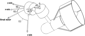
An underwater vehicle has six degrees of freedom including transitional movements in three directions and rotational movements around each of three axes according to the Figure 1. Usually, two types of coordinate systems are used to describe the kinematics and dynamics of the body that includes the earth coordinate system (ECS) frame and the body-fixed coordinate system that is connected to the body (Figure 1).
Figure 1. Coordinate systems and definition of variables for general motion of the vehicle in six degrees of freedom
The general dynamic equation of the underwater vehicle with six degrees of freedom as follow:
$M \dot{v}+C(v) v+D(v) v+g(\eta)=\tau_{c}+\tau_{e}$ (1)
This equation is based on the body-fixed reference frame attached to the underwater vehicle. Here “u” is linear and angular velocity with respect to body coordinate system and “h” is linear and angular position with respect to the inertial coordinate system.
Matrix M consists of two semesters MRB (rigid body) and MADD (added mass) are defined as follow:
$M=M_{R B}+M_{A D D}$ (2)
$M_{A D D}=\left(\begin{array}{cccccc}X_{\dot{u}} & X_{\dot{v}} & X_{\dot{w}} & X_{\dot{p}} & X_{\dot{q}} & X_{\dot{r}} \\ Y_{\dot{u}} & Y_{\dot{v}} & Y_{\dot{w}} & Y_{\dot{p}} & Y_{\dot{q}} & Y_{\dot{r}} \\ Z_{\dot{u}} & Z_{\dot{v}} & Z_{\dot{w}} & Z_{\dot{p}} & Z_{\dot{q}} & Z_{\dot{r}} \\ K_{\dot{u}} & K_{\dot{v}} & K_{\dot{w}} & K_{\dot{p}} & K_{\dot{q}} & K_{\dot{r}} \\ M_{\dot{u}} & M_{\dot{v}} & M_{\dot{w}} & M_{\dot{p}} & M_{\dot{q}} & M_{\dot{r}} \\ N_{\dot{u}} & N_{\dot{v}} & N_{\dot{w}} & N_{\dot{p}} & N_{\dot{q}} & N_{\dot{r}}\end{array}\right)$
$M_{R B}=\left(\begin{array}{cccccc}m & 0 & 0 & 0 & m z_{G} & -m y_{G} \\ 0 & m & 0 & -m z_{G} & 0 & m x_{G} \\ 0 & 0 & m & m y_{G} & -m x_{G} & 0 \\ 0 & -m z_{G} & m y_{G} & I_{x} & -I_{x y} & -I_{x z} \\ m z_{G} & 0 & -m x_{G} & -I_{x y} & I_{y} & -I_{y z} \\ -m y_{G} & m x_{G} & 0 & -I_{x z} & -I_{y z} & I_{z}\end{array}\right)$
Matrix C is known as coriolis or centripetal matrix is defined as follow:
$C(v)=C_{R B}(v)+C_{A D D}(v)$ (3)
$C_{R B}(v)=\left(\begin{array}{cc}0_{3 \times 3} & C_{12}(v) \\ -C_{12}^{T}(v) & C_{22}(v)\end{array}\right)$
$C_{12}(v)$$=\left(\begin{array}{ccc}m\left(y_{G} q+z_{G} r\right) & -m\left(x_{G} q-w\right) & -m\left(x_{G} R+v\right) \\ -m\left(y_{G} q+w\right) & m\left(z_{G} r+x_{G} p\right) & -m\left(y_{G} r-u\right) \\ -m\left(z_{G} p-v\right) & -m\left(z_{G} q+u\right) & m\left(x_{G} p+y_{G} q\right)\end{array}\right)$
$C_{22}(v)=\left(\begin{array}{ccc}0 & -I_{y z} q-I_{x z} p+I_{z} r & I_{y z} r+I_{x y} p-I_{y} q \\ I_{y z} q+I_{x z} p-I_{z} r & 0 & -I_{x z} r-I_{x y} q+I_{x} p \\ -I_{y z} r-I_{x y} p+I_{y} q & I_{x z} r+I_{x y} q-I_{x} p & 0\end{array}\right)$
$\mathrm{C}_{\mathrm{ADD}}(v)=\left(\begin{array}{cccccc}0 & 0 & 0 & 0 & -a_{3} & a_{2} \\ 0 & 0 & 0 & a_{3} & 0 & -a_{1} \\ 0 & 0 & 0 & -a_{2} & a_{1} & 0 \\ 0 & -a_{3} & a_{2} & 0 & -b_{3} & b_{2} \\ a_{3} & 0 & -a_{1} & b_{3} & 0 & -b_{1} \\ -a_{2} & a_{1} & 0 & -b_{2} & b_{1} & 0\end{array}\right)$
$a_{1}=X_{\dot{u}} u+X_{\dot{v}} v+X_{\dot{w}} w+X_{p} p+X_{\dot{q}} q+X_{\dot{r}} r$
$a_{2}=X_{\dot{u}} u+Y_{\dot{v}} v+Y_{\dot{w}} w+Y_{\dot{p}} p+Y_{\dot{q}} q+Y_{\dot{r}} r$
$a_{3}=X_{\dot{u}} u+Y_{\dot{v}} v+Z_{\dot{w}} w+Z_{\dot{p}} p+Z_{\dot{q}} q+Z_{\dot{r}} r$
$b_{1}=X_{\dot{u}} u+Y_{\dot{v}} v+Z_{\dot{w}} w+K_{\dot{p}} p+K_{\dot{q}} q+K_{\dot{r}} r$
$b_{2}=X_{\dot{u}} u+Y_{\dot{v}} v+Z_{\dot{w}} w+K_{\dot{p}} p+M_{\dot{q}} q+M_{r} r$
$b_{3}=X_{\dot{u}} u+Y_{\dot{v}} v+Z_{\dot{w}} w+K_{\dot{p}} p+M_{\dot{q}} q+N_{\dot{r}} r$
Matrix MADD and CADD obtained according analysis methods based on potential theory [25]. Matrix D including hydrodynamic forces is as follow:
$\begin{aligned} D(V)=-\operatorname{diag} &\left(X_{u}+X_{u|u|}|u|, Y_{v}+Y_{v|v|}|v|, Z_{w}\right.\\ &+Z_{w|w|}|w|, K_{p}+K_{p|p|}|p|, M_{q} \\ & \left.+M_{q|q|}|q|, N_{r}+N_{r|r|}|r|\right) \end{aligned}$ (4)
Assuming the robot is fully immersed, the drag coefficient of linear speed obtained by ANSYS simulation software and drag coefficients of rotational speed obtained from the analytical method [26]. Matrix $g$ consists of the gravity and buoyancy force. Here, the gravity and buoyancy vector $g(\eta)$ can be negligible because the presented robot has neutral buoyancy and center of gravity coincide with the center of buoyancy. Vector $\tau_{c}$ represents the control forces and torques vector that is created by thrusters and $\tau_{e}$ shows external forces and torques known as disturbance on the system.
Most underwater robots that can control six degrees of freedom, for hovering motion need an over actuated mechanism with eight fixed thrusters [27, 28]. The number of thrusters affects the capacity of the power supply, and a large power supply adds more weight to an underwater robot. This paper presents a specific type of tilt thruster underwater vehicle with 4 thrusters that the orientation of each of them is as a function of time allowing simultaneously control of six degrees of freedom. Mechanisms used to change the orientation of thrusters can be parallel robots mechanisms or multi directional thrust vector system (MTVS) [8] or two perpendicular servo motors. Here, a robotic platform is introduced which the orientation of each thruster is controlled by two perpendicular servo motors (Figure 2).
Change the thruster orientation as a function of time making it possible to move simultaneously to different directions and increase hovering ability. The Figure 3 shows how the rotation of servo motors impact on the orientation of thrust vector.
Figure 2. New tilt thruster with two servo motors for each thruster
Figure 3. Thrust vector orientation with respect to the local coordinate system
As shown in Figure 3, the rotation of the first servo motor with angle $\varphi_{1}$ around the y-axis and rotation of second servo motor with angle $\varphi_{2}$ around the z-axis, thrust vector orientation with respect to local coordinate system is according to Figure 3. Relationships between $\theta_{1}, \theta_{2}, \theta_{3}$ with $\varphi_{1}, \varphi_{2}$ are based on following equations.
$\theta_{1}=\operatorname{Cos}^{-1}\left(\cos \left(\varphi_{1}\right) \operatorname{Cos}\left(\varphi_{2}\right)\right)$
$\theta_{2}=\operatorname{Cos}^{-1}\left(\cos \left(\varphi_{1}\right) \operatorname{Sin}\left(\varphi_{2}\right)\right)$
$\theta_{3}=\frac{\Pi}{2}-\varphi_{1}$ (5)
The relationship between $\tau_{\mathrm{c}}$ and forces created by the thrusters is:
$\tau_{c}=B\left(\theta_{1}, \theta_{2}, \theta_{3}\right)\left[\begin{array}{c}f_{1} \\ f_{2} \\ f_{3} \\ f_{4}\end{array}\right]$ (6)
where, matrix B is:
$B=\left(\begin{array}{cccc}c\left(\theta_{1}\right)_{1} & c\left(\theta_{1}\right)_{2} & c\left(\theta_{1}\right)_{3} & c\left(\theta_{1}\right)_{4} \\ c\left(\theta_{2}\right)_{1} & c\left(\theta_{2}\right)_{2} & c\left(\theta_{2}\right)_{3} & c\left(\theta_{2}\right)_{4} \\ c\left(\theta_{3}\right)_{1} & c\left(\theta_{3}\right)_{2} & c\left(\theta_{3}\right)_{3} & c\left(\theta_{3}\right)_{4} \\ -\frac{w}{2} c\left(\theta_{3}\right)_{1} & -\frac{w}{2} c\left(\theta_{3}\right)_{2} & \frac{w}{2} c\left(\theta_{3}\right)_{3} & \frac{w}{2} c\left(\theta_{3}\right)_{4} \\ -\frac{l}{2} c\left(\theta_{3}\right)_{1} & \frac{l}{2} c\left(\theta_{3}\right)_{2} & \frac{l}{2} c\left(\theta_{3}\right)_{3} & -\frac{l}{2} c\left(\theta_{3}\right)_{4} \\ a & b & c & d\end{array}\right)$
$\begin{aligned} a &=\frac{w}{2} c\left(\theta_{1}\right)_{1}+\frac{l}{2} c\left(\theta_{2}\right)_{1} \\ b &=\frac{w}{2} c\left(\theta_{1}\right)_{2}-\frac{l}{2} c\left(\theta_{2}\right)_{2} \\ c &=-\frac{w}{2} c\left(\theta_{1}\right)_{3}-\frac{l}{2} c\left(\theta_{2}\right)_{3} \\ d &=-\frac{w}{2} c\left(\theta_{1}\right)_{4}+\frac{l}{2} c\left(\theta_{2}\right)_{4} \end{aligned}$
In these equations $c$ is abbreviation of $\cos$.
3.1 Control of new tilt thruster underwater robot
After the implementation of nonlinear coupled dynamic model of robot in MATLAB software and providing an algorithm for the calculation, control inputs must be created by each of thrusters. Orientation of each thruster is determined by comparing of real trajectory with desired trajectory of underwater robot. PID controller is used to control of each of the degrees of freedom of the robot.
To demonstration of underwater robot ability to track the complex trajectory, in this section a wide variety of paths are considered.
4.1 Helical motion
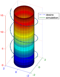
Figure 4. Helical motion of new variable thrust vector underwater vehicle
The underwater robots can be used to inspect the underwater constructions [29, 30]. For the inspection of a cylindrical tank under the sea, this new tilt thruster underwater vehicle with helical motion can be used, that require simultaneously control of surge, sway and heave. For this motion, sinusoidal desired path is considered for surge and cosine desired path for sway.
$\begin{aligned} x_{\text {desired }} &=r \sin (\omega t) \\ y_{\text {desired }} &=r \cos (\omega t) \\ z_{\text {desired }}=a t, a &=.25, r=2, \omega=\pi / 10 \end{aligned}$ (7)
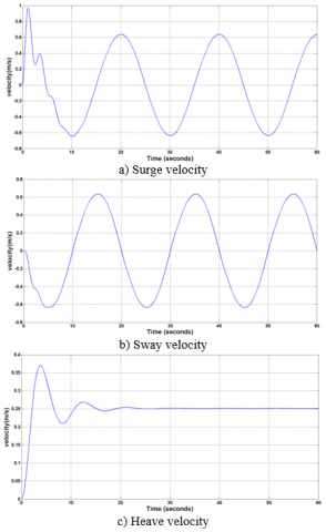
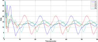
In Figure 4, the underwater vehicle motion in the helical trajectory is observed. In Figure 5 surge, sway and heave velocities are shown. In Figure 6, thrust forces and in Figure 7, rotation of servo motors is determined. F1, F2, F3 and F4 are the forces of thruster 1, thruster 2, thruster 3 and thruster 4, respectively
Figure 5. Surge, sway and heave velocities of underwater vehicle for helical motion
Figure 6. Thruster forces for helical motion
Figure 7. Servo motors rotation of thrusters for helical motion
4.2 Toroidal spiral motion
Now, complex motion is considered. In this motion, underwater torus shape is considered, which is inspected by robot. This torus has a diameter of m and radius of the center line is 3 m.
$x_{\text {desired }}=\cos (\omega t)(b+\operatorname{asin}(c \omega t))$ for Surge
$y_{\text {desired }}=\sin (\omega t)(b+\operatorname{asin}(c \omega t))$ for Sway
$z_{\text {desired }}=a \cos (c \omega t)$ for Heave, $a=1$,
$\quad \mathrm{b}=3, \mathrm{c}=15, \omega=0.04$ (8)
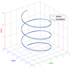
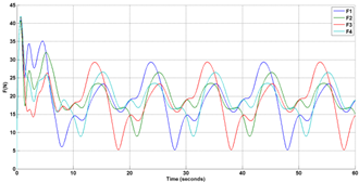
In Figure 8, the underwater vehicle motion in the Toroidal spiral trajectory is observed. New tilt thruster robot can move in toroidal spiral curve. In Figure 9 surge, sway and heave velocities are shown. In Figure 10, thrust forces and in Figure 11, rotation of servo motors is determined.
Figure 8. Toroidal spiral motion of new variable thrust vector underwater vehicle
Figure 9. Surge, sway and heave velocities of underwater vehicle for Toroidal spiral motion
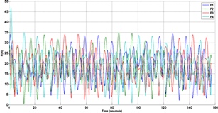
Figure 10. Thruster forces for Toroidal spiral motion
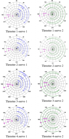
Figure 11. Servo motors rotation of thrusters for toroidal spiral motion
4.3 Loxodrome motion
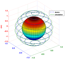
To inspect an underwater spherical tank with a radius of $1 \mathrm{~m}$, this robot is used that able to moves in the direction of loxodrome curve for 2 min and 37 sec to do a full scan.
$x_{\text {desired }}=r \sin (w t)$ cos $(\mathrm{cwt})$ for Surge
$y_{\text {desired }}=r \sin (w t) \sin (\mathrm{cwt})$ for Sway
$z_{\text {desired }}=r \cos (w t)$ for Heave, $r=1.5, \mathrm{c}=20, w=0.02$ (9)
In Figure 12, the robot motion in the specified path is observed. In Figure 13, the surge, sway, heave velocity are shown. In Figure 14 thrust forces and in Figure 15 rotations of servo motors of thrusters is determined.
Figure 12. Loxodrome motion of underwater vehicle
Figure 13. Surge, sway and heave velocities of underwater vehicle for loxodrome motion
Figure 14. Thruster forces for loxodrome motion
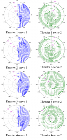
Figure 15. Servo motors rotation of thrusters for loxodrome motion
4.4 Simultaneously control of surge, sway, heave, roll, yaw and pitch with variable inputs
Here, the general-complex motion of the robot is considered. All six degrees of freedom are controlled simultaneously with different inputs. The following trajectory is considered:
$x_{\text {desired }}=2 r \cos (w t / 2)^{2}$
$y_{\text {desired }}=2 r \sin (w t / 2) \cos (w t / 2)$
$z_{\text {desired }}=2 r \sin (w t / 2), w=\pi / 10, r=1$ (10)
The combination of these 3 moves creates Viviani curve. The Viviani curve is the intersection of a sphere of radius $2 r$ with a cylinder of radius $r$ that is tangent to the sphere and passes through the center of the sphere (Figure 16).
Also, it is considered:
$\varphi_{\text {desire }}=(\pi / 2) \sin (w t)$ for roll angle
$\theta_{\text {desire }}=(\pi / 3) \sin (w t)$ for pitch angle
$\psi_{\text {desire }}=(\pi / 2) \sin (w t)$ for yaw angle, $w=\pi / 10$ (11)
Simulation results are shown by the Figure 17.
Figure 16. Viviani curve as complex trajectory
Figure 17. Comparison of desired orientation and position with orientation and position of simulation for Viviani curve
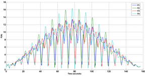
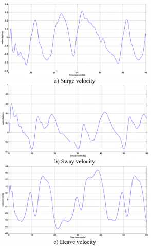
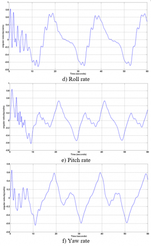
In Figure 18 surge, sway, heave, roll, pitch and yaw velocities are shown. In Figure 19 thrust forces and in Figure 20 rotation of servo motors of thrusters are determined.
The tracking of these complex trajectories demonstrates the flexibility and powerful of the new variable thrust vector underwater vehicle. Therefor this underwater vehicle can be used for underwater complex missions and operations.
This paper has presented a robotic platform that with continuous and independent orientation of each thruster will be able to simultaneously control six degrees of freedom. In this platform, the orientation of each thruster is controlled by two perpendicular servo motors. While, ODYSSEY-IV [6] provides four degrees of freedom control; the Nereus [7] has fixed main thrusters; hovering motion is not possible for the thrust-vectoring mechanism in the ref. [8]; thrusters could only switch between 0 and 90 degrees in underwater robotic platform presented in the ref. [10], that, due to frequent switching of the thruster configuration, the control of the six degrees of freedom will be along with error and robot depreciation; most underwater robots, that can control six degrees of freedom, need an over actuated mechanism with eight fixed thrusters [27, 28]. Underwater vehicle proposed in current paper presents a specific type of tilt thruster underwater vehicle with four thrusters that the orientation of each of them is as a function of time allowing simultaneously control of six degrees of freedom.
Figure 18. Surge, sway, heave, roll, pitch and yaw velocities of underwater vehicle for Viviani curve motion
Figure 19. Thruster forces for Simultaneously control of surge, sway, heave, roll, yaw and pitch
Figure 20. Servo motors rotation of thrusters for Simultaneously control of surge, sway, heave, roll, yaw and pitch
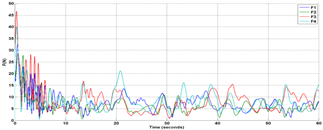
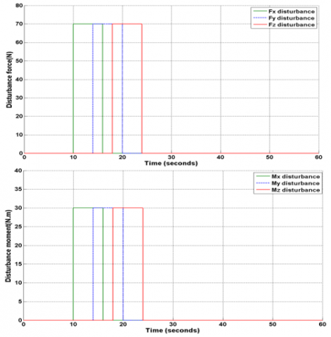
The disturbances are caused by underwater flow or forces and moments created by mechanical manipulator mounted on the robotic platform. For evaluation of robustness in the presence of disturbances, forces and moments disturbances are considered as Figure 21. As shown in Figure 21 forces and moment disturbance are applied within 10 to 24 seconds and they overlap each other.
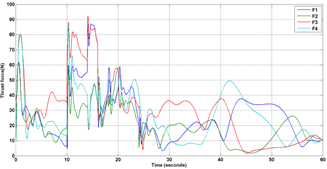
Thrust forces created under the disturbance are shown in Figure 22. Comparison between X, Y and Z desired and X, Y and Z simulation and comparison between Roll, Pitch and Yaw desired and Roll, Pitch and Yaw simulation under the disturbance are shown in Figure 23.
Figure 21. Force and moment disturbances
Figure 22. Thrust forces created under the disturbance
Figure 23. Comparison between X, Y, Z, Roll, Pitch and Yaw desired and X, Y, Z, Roll, Pitch and Yaw simulation
These results have shown that the system and controller are robust against environmental disturbances.
For evaluation robot controller resistance against uncertainty of hydrodynamic parameters, it is assumed that, in the worst case, hydrodynamic coefficients obtained from the laboratory to 100% is incompatible with real values, thus increasing the hydrodynamic coefficients to 100% and the robustness of the controller is evaluated.
Figure 24. Helical motion by considering 100% of the difference between laboratory coefficients with actual values
Figure 25. Thruster forces by considering 100% of the difference between laboratory coefficients with actual values
Therefore, by placement 2×MADD instead of MADD and 2×CADD instead of CADD and 2×D instead of D in dynamic equations in helical motion Figure 24 is obtained.
By comparing the Figures 24 and 25 with Figure 4 and 6 identified that the error rate increased slightly and thruster forces increased about 7 N. Since these changes are very small, therefore, it can be said that this system and controller is robust against uncertainty of hydrodynamic parameters.
This paper presented specific types of underwater robotic platform having four thrusters with variable thrust vectoring which each thruster includes two perpendicular servo motors. Independent time-varying orientation of each thruster made it possible to simultaneously control up to six degrees of freedom that results in high maneuverability in comparing the other underwater vehicles, so that this new tilt thruster underwater vehicle can track the complex trajectories. Also, system and controller are investigated under environmental disturbances and uncertainty of hydrodynamic parameters, and the robustness is demonstrated. Capabilities and advantages of this new robot allow using in underwater structures and many applications.
[1] Amirkolaii, F.S., Ghasemi, R.H. (2016). Representation of an autonomous underwater vehicle and trajectory controller design for in-water ship hull inspection. Modares Mechanical Engineering, 15(10): 12-22.
[2] Amirkolaii, F.S., Ghasemi, R.H. (2020). The control of a new underwater vehicle with high stability and maneuverability in order to chase the target. Journal of High Speed Craft Engineering, 18(55): 28-39.
[3] Mehrabani A.H., Ghasemi, R.H. (2020). Representation of dynamic positioning on hovering type autonomous underwater vehicle in precise welding operations. Journal of Harbin Institute of Technology. https://doi.org/10.11916/j.issn.1005-9113.2019049
[4] Karimi, A., Ghasemi, R.H. (2017). Equipping of a hovering type autonomous underwater vehicle with ballast tanks and its effect on degrees of freedom. Modares Mechanical Engineering, 17(7): 397-404.
[5] Karimi, A., Ghasemi, R.H. (2021). Dynamic Modeling of a Hovering Type Autonomous Underwater Vehicle (HAUV) with Ballast Tank. International Journal of Modelling, Identification and Control, in press.
[6] Eskesen, J., Owens, D., Soroka, M., Morash, J., Hover, F.S., Chrysosstomidis C. (2009). Design and performance of ODYSSEY IV: A deep ocean hover-capable AUV. MIT Sea Grant College Program Report, Dept. Mech. Eng., MIT.
[7] Jakuba, M.V., Yoerger, D.R., Whitcomb, L.L. (2007). Longitudinal control design and performance evaluation for the Nereus 11000 m underwater vehicle. Oceans Conference, Vancouver, BC, pp. 1-10. https://doi.org/10.1109/OCEANS.2007.4449305
[8] Kopman, V., Cavaliere, N., Porfiri, M. (2012). MASUV-1: A Miniature underwater vehicle with multidirectional thrust vectoring for safe animal interactions. IEEE/ASME Trans. Mechatronics, 17(3): 563-571. https://doi.org/10.1109/TMECH.2011.2108307
[9] Lopez, R., Torres, I., Escareño, J., Salazar, S., Palomino, A., (2010). Quad-tilting thrusters micro submarine: Modeling and control of the attitude. 20th International Conference on Electronics, Communications and Computers (CONIELECOMP), Cholula, pp. 85-89. https://doi.org/10.1109/CONIELECOMP.2010.5440791
[10] Jin, S., Kim, J., Kim, J., Seo, T. (2014). Six-degree-of-freedom hovering control of an underwater robotic platform with four tilting thrusters via selective switching control. IEEE/ASME Transaction on Mechatronics, 20(5): 2370-2378. https://doi.org/10.1109/TMECH.2014.2378286
[11] Gertler, M., Hagen, G. (1967). Standard equations of motion for submarine simulation. Naval Ship Research and Development Center.
[12] Yuh, J., (1990). Modeling and control of underwater robotic vehicles. IEEE Transaction on Systems, Man and Cybernetics, 20(6): 1475-1483. https://doi.org/10.1109/21.61218
[13] Nahon, M. (1996). A simplified dynamics model for autonomous underwater vehicles. Proceedings of the Symposium on Autonomous Underwater Vehicle Technology, Monterey, CA, USA, pp. 373-379. https://doi.org/10.1109/AUV.1996.532437
[14] Conte, G., Serrani, A. (1996). Modeling and simulation of underwater vehicles. Proceedings of Joint Conference on Control Applications Intelligent Control and Computer Aided Control System Design, Dearborn, MI, USA, pp. 62-67. https://doi.org/1010.1109/CACSD.1996.555198
[15] Yuh, J., Holley, W.E. (1988). Application of discrete-time model reference adaptive control to industrial robots: A computer simulation. Journal of Manufacturing Systems, 7(1): 47-56. https://doi.org/10.1016/0278-6125(88)90032-5
[16] Fossen, T. (1994). Guidance and Control of Ocean Vehicles. John Wiley & Sons, New York.
[17] Antonelli, G., Chiaverini, S., Sarkar, N., West, M. (2001). Adaptive control of an autonomous underwater vehicle: Experimental results on ODIN. IEEE Transactions on Control Systems Technology, 9(5): 756-765. https://doi.org/10.1109/87.944470
[18] Zilouchian, A., Jamshidi, M. (2001). Intelligent Control Systems Using Soft Computing Methodologies, CRC Press, Boca Raton.
[19] Hasanzadeh Ghasemi, R., Khodayari, M.H. (2019). Sliding mode control of an autonomous underwater vehicle with parametric uncertainty and sensors noises. Journal of Mechanical Engineering, 48(4): 107-116.
[20] Zarenezhad, S., Ghasemi, R.H. (2016). Investigation and calculation of hydrodynamic coefficient for an AUV by analytical-experimental method. 18th Marine Industries Conference, Kish Island, Iran. http://iraname.com/book/proceedings/MIC2016EN.pdf
[21] Kadkhodaei, A., Hasanzadeh Ghasemi, R., (2017). Inspection of undersea oil and gas pipelines by new variable thrust vector underwater robotic platform. Marine Engineering, 12(24): 127-133.
[22] Prestero, T. (2001). Verification of a six-degree of freedom simulation model for the REMUS autonomous underwater vehicle. Master Thesis, Massachusetts Institute of Technology.
[23] Pyo, J., Joe, H.G., Kim, J.H., Elibol, A., Yu, S.C. (2013). Development of hovering-type AUV “Cyclops” for precision observation. 2013 OCEANS - San Diego, San Diego, CA, pp. 1-5. https://doi.org/10.23919/OCEANS.2013.6741060
[24] Choi, H.T., Hanai, A., Choi, S.K., Yuh, J. (2003). Development of an underwater robot, ODIN-III. Proceedings 2003 IEEE/RSJ International Conference on Intelligent Robots and Systems (IROS 2003) (Cat. No.03CH37453), Las Vegas, NV, USA, 1: 836-841. https://doi.org/10.1109/IROS.2003.1250733
[25] Newman, J.N. (1997). Hydrodynamics of Slender Bodies. MIT Press.
[26] Georgiades, C. (2005). Simulation and control of an underwater hexapod robot. Master thesis, Department of Mechanical Engineering, McGill University, Canada.
[27] Ribas, D., Palomeras, N., Ridao, P., Carreras, M., Mallios, A. (2012). Girona 500 AUV: From survey to intervention. IEEE/ASME Transactions on Mechatronics, 17(1): 46-53. https://doi.org/10.1109/TMECH.2011.2174065
[28] Zhao, S., Yuh, J. (2005). Experimental study on advanced underwater robot control. IEEE Transactions on Robotics, 21(4): 695-703. https://doi.org/10.1109/TRO.2005.844682
[29] Zhang, F.T., Thon, J., Thon, C., Tan, X.B. (2014). Miniature underwater glider: Design and experimental results. IEEE/ASME Transactions on Mechatronics, 19(1): 394-399. https://doi.org/10.1109/TMECH.2013.2279033
[30] Serchi, F.G., Arienti, A., Laschi, C. (2013). Biomimetic vortex propulsion: Toward the new paradigm of soft unmanned underwater vehicles. IEEE/ASME Transactions on Mechatronics, 18(2): 484-493. https://doi.org/10.1109/TMECH.2012.2220978