Balamurugan Manoharan* | Sarat Kumar Sahoo
© 2021 IIETA. This article is published by IIETA and is licensed under the CC BY 4.0 license (http://creativecommons.org/licenses/by/4.0/).
OPEN ACCESS
This paper presents the Direct Power Control (DPC) strategy for Multilevel Multistring Inverter fed Photovoltaic (PV) system to control the instantaneous active and reactive power. The proposed system consists of PV strings, boost converter and three phase three level cascaded H-bridge (CHB) inverter. In multistring topology, each PV string is connected to the dc/dc converter and the distributed MPPT control algorithm is connected to the central inverter. The Space Vector Modulation (SVM) based DPC approach is used to obtain the constant switching frequency and reduced power ripple. The detailed model of the proposed system is developed in Matlab to evaluate the performance. A laboratory based prototype of the proposed system is developed to realize the system in real time. dSPACE DS1103 is used as the control interface to perform the real time implementation (RTI). Power Quality Analyser (PQ-Box 200) is used to analyse the system parameters like voltage, current and Total Harmonic Distortion (THD) of inverter. The effectiveness of the proposed system has been validated with the help of simulation and the experimental results.
photovoltaic systems, maximum power point tracker, digital signal processor, Matlab, reactive power control, power quality
In recent years, there is a great attention in the development of renewable energy sources due to the depletion of fossil fuels and burning of those fuels causes the environment pollution. Renewable energy sources are pollution free energies and they contribute to reduce the greenhouse effects. Solar, Wind, Tidal, biomass are the different types of renewable energy sources are utilized to generate electricity. Out of these four sources, solar energy is one of the most prominent alternative sources of energy because of surplus amount of energy from the sun and also the financial support provided by the government and in recent times solar panel costs are drastically decreased, which will lead to the reduction in the amount of per unit electricity generated. Based on the Global Status report of Renewable 2015, Global Installed Capacity of Solar PV is 3.7 GW in 2004 and it is increased up to 177 GW in 2014.
Due to the increase in the capacity of PV, the dependence of grid power is reduced and therefore the solar energy is evolved has an alternative to conventional energy. PV systems are mostly rated for domestic, industrial and commercial application from few kilowatts to several megawatts in roof top mounted or building-incorporated systems. Nowadays, most of PV systems are integrated with grid because for stand-alone systems, batteries are required to store the energy which will increase the cost of the entire system. The government has announced the subsidies those who are generating the power on their own and also injected the generated power into the grid, therefore people shift their focus towards the PV system. [1].
Conventionally most of the applications use three phase rectifiers to interface the renewable energy sources into the grid. It is very simple structure but it has the drawback of unidirectional power flow, power factor is low and the high distortion of input current. Then the two-level voltage source inverter (VSI) is used for converting the direct current (DC) to alternative current (AC) in order to deliver the power into the grid. However, this topology has very high switching stress because this circuit has only six switches therefore when very high dc voltage is applied to the inverter the switch has to withstand the voltage so the stress has been very high. To avoid this problem Multilevel inverters (MLI) are introduced in grid connected systems. Neutral Point Clamped MLI (NPC-MLI), Flying Capacitor MLI (FC-MLI) and Cascaded H-Bridge MLI (CHB-MLI) are the three different types of MLI. However, CHB-MLI has been widely used in the application of renewable energy systems because of the separate DC source for each bridge and it is also easy to interface with the hybrid systems [2].
There are four different types of PV configurations which are centralized topology, string topology, ac module topology and multistring topology. In most of the large power plant, centralized topology is installed where the large numbers of panels are connected in series or parallel in one string with central inverter. The major advantages of this topology are the simple structure and less maintenance. This topology has highly suffered due to the partial shading and also fails to determine the peak point because of the centralized MPPT algorithm [3, 4].
In String topology, the panels are divided into separate sections, where each string is connected to DC/DC converter and DC/AC inverter where the distributed MPPT scheme is applied to improve the power produced the strings. The advantages of these topologies are the higher power production and distributed MPPT scheme. This topology has applicable to small scale systems because of the complex structure and also cost of the topology is very high.
AC-Module topology has one dedicated converter for each module and this topology is widely used in domestic and small-scale applications. The drawback of the topology is high cost and complex structure.
Therefore, by combining the merits of centralized topology and string topology the new topology is evolved and it is called as multistring topology. In multistring topology, each PV string is connected to the dc/dc converter and the distributed MPPT control algorithm is connected to the central inverter. This topology has been mostly used in medium voltage high power applications because of the modularity structure and it is easy to increase rating of the system by connecting the additional string to the topology.
Because of the penetration of non-conventional energy sources into the grid advanced control techniques are essential to ensure the power quality. There are two advanced control techniques which are mostly used in grid connected systems which are Voltage Oriented Control (VOC) and Direct Power Control (DPC). Both of these methods provide very good dynamic response with low harmonic distortion [5, 6]. However, VOC is called as indirect power control because it consists of modulator to generate the switching pulse. The presence of modulator will distort the voltage and current when it is delivered into the grid. To avoid this problem bulky filter inductance and capacitance are connected on the load side to eliminate the non-linearity in the system. On the other hand, DPC is called as the direct control because the switching pulses are generated with the estimated power and voltage instead of modulator. DPC has become more popular because of robustness and provides an excellent transient response in terms of dynamic operating conditions [7-12].
The most frequently used DPC strategy is Look-up table DPC (LUT-DPC) which consists of non-linear hysteresis controller. Based on the estimation of grid voltage, generated power and the grid voltage position sector the LUT is generated for different sectors. LUT contains the information when the switch has to turn on/off based on the location of the voltage vector. This method is very simple to implement and there is no coordinated transformation in DPC and the inner current control arrangement is also eliminated. But, drawback in this control technique is the presence of very high ripple and variable switching frequency [13-16]. Virtual Flux DPC (VF-DPC) is used to eliminate problem of variable switching frequency by estimating the virtual flux, power and voltage. Instead of grid voltage position sector virtual flux is estimated by using the transformation equations [17-19]. This control strategy offers excellent steady state response and fast control. However, it is very difficult to realize the system in real time because very high processors are required to calculate the sample time [20].
Space Vector Modulation (SVM-DPC) technique used to eliminate the power ripples and variable switching frequency with the addition of Proportional Integral (PI) controllers is used to generate the voltage reference. This control strategy uses certain complex equations to generate the switching pulse [21-24]. The concept of Predictive control is also introduced in DPC such as Model Predictive control (MPC). MPC is used to generate the control pulse by predicting the behavior of switching instants by using the cost function analysis. MPC offers very high control compared to conventional techniques but if the prediction is wrong the behavior of the entire system is changed. Therefore, this strategy offers best control only when the prediction is correct [25-29].
Even though the concept of DPC was proposed almost two decades ago still the issues have not been solved yet [30, 31]. The problems related to tuning and the strategies used for implementation and the certain evaluation of experimental results has not been analyzed [32-34]. The research in the area of multilevel inverters where the DPC strategy is implemented is very less when compared to two level VSI.
The main contribution of this paper is to interface PV string with the grid through the boost converter and multilevel inverter. Maximum Power Point Tracking (MPPT) algorithm is implemented to generate duty cycle for the converter. DPC strategy is applied to the multilevel inverter to analyse the performance of the system. In this paper the three phase CHB-MLI inverter is used to interface the PV system with the grid. The simulation studies are performed for the proposed system to analyse the performance of the proposed system for static and dynamic conditions by using DPC. A laboratory based prototype of the entire system is developed to realize the system in real time. This paper has organized in the subsequent sections. Section II presents description of the proposed system and the DPC-SVM strategy has been discussed in Section III. The simulation results of the system have been presented in Section IV and in Section V the experimental validations have been discussion. Finally, the conclusion has been discussed in Section VI.
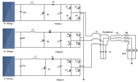
The Multilevel Multistring inverter fed PV system is displayed in Figure 1 which consists of three phase three level CHB inverter has one H-bridge which consists of four switches along with DC source in each phase. Therefore, in each phase, one PV string along with the boost converter is connected to the H-bridge. Each PV string has 6 panels where 2 panels are connected in series likewise 3 sets of panels are connected in parallel with the capacity of 1500W.
Figure 1. Schematic diagram of the proposed system
The Capacitor Cpv is connected across each string to reduce the ripples produced by panels. The DC/DC boost converter remains connected to each string to raise the voltage level generated by the panel in order to connect to the grid. To operate the PV string at the maximum level several distributed Maximum Power Point Tracking (MPPT) techniques are used to determine the maximum operative point during various climatic conditions. Since this work is based on DPC control not much focus is given to the MPPT. Therefore, conventionally used Perturb and Observe (P&O) method is used to determine peak point and produce the duty cycle for the boost converter by matching the load impedance along with source impedance. The inverter is coupled to the grid through the isolation transformer with filter inductance Lf and filter Capacitance Cf to eliminate the ripples in the system. The Lg and Rg represents the impedance of the grid.
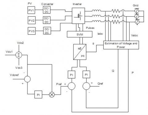
Figure 2. DPC control scheme
Direct Power Control for multilevel inverter is used to estimate the voltage by using the currents measured and the system parameters instead of measuring the voltage through the sensors to eliminate the complexities in the system. The constant switching frequency has been accomplished by integrating the linear voltage vector along with the average voltage vector. The control scheme of DPC-SVM is presented in Figure 2. To generate the active power reference Pref summation of all three DC link voltage is taken as measured voltage which is subtracted from the DC reference voltage and error is generated. PI controller is used to minimize error and it is multiplied with the DC link voltage. The reactive power reference Qref is reserved as zero to preserve unity power factor. The space vector diagram of three phase inverter is shown in Figure 3 which consists of six sectors where the duration of each sector is around 60○. There are 27 voltage vectors is generated for the inverter. Out of these 27 vectors, 19 vectors are active switching states and the remaining 9 vectors are redundant switching states. The space vector consists of three layers which are external layer, central layer and the internal layer. The external layer of the vector is formed by one switching state, the central layer and the internal layer are formed by two switching states. At the origin three switching vectors are present which are called null vectors. To calculate the instantaneous active and reactive power can be designed by
$p(s)={{u}_{a}}*{{i}_{a}}+{{u}_{b}}*{{i}_{b}}+{{u}_{c}}*{{i}_{c}}$ (1)
$q(s)=\frac{1}{\sqrt{3}}\left[ \left( {{u}_{a}}-{{u}_{b}} \right)*{{i}_{c}}+\left( {{u}_{b}}-{{u}_{c}} \right)*{{i}_{a}}+\left( {{u}_{c}}-{{u}_{a}} \right)*{{i}_{b}} \right]$ (2)
where, ua, ub, uc are the voltage generated by the grid, ia, ib, ic are the current generated by the inverter and p(s) and q(s) are estimated active and reactive power.
The instantaneous active and reactive power can also be designed in stationary reference frame in terms of uα, uβ, iα, iβ by using three phase to two phase transformations is given as follows,
$\left[\begin{array}{l}p(s) \\ q(s)\end{array}\right]=\left[\begin{array}{ll}u_{\alpha} & u_{\beta} \\ -u_{\beta} & u_{\alpha}\end{array}\right]\left[\begin{array}{l}i_{\alpha} \\ i_{\beta}\end{array}\right]$ (3)
The space vector is divided into six sectors which are calculated as follows,
$(n-5)\frac{\pi }{3}\le n<\left( n-1 \right)\frac{\pi }{3}$ (4)
where, n = 1, 2... 6.
$\theta ={{\tan }^{-1}}\left( \frac{{{u}_{\beta }}}{{{u}_{\alpha }}} \right)$ (5)
Figure 3. Vector representation of three level CHB inverter
The grid voltage position vector (θ) is calculated for the voltage generated by two phase transformations and then the pulses are generated by using SVM modulator.
Matlab Simulation software tool is used to simulate the proposed system to determine the performance of the system.
The parameters used for simulation are listed in Table 1. The switching frequency of proposed system is set at 20 kHz and the sampling time is 50us and to preserve unity power factor the reactive power reference is to be set at zero. The specifications of the EMM VEE 250W PV panel are listed in Table 2.
Figure 4 displays the waveforms of voltage, current, power and the DC link voltage of all three PV strings as the result of simulation. At t = 0.05s the MPPT algorithm tracks the peak point therefore the voltage, current and power reaches the maximum level but due to the changes in irradiation and temperature the peak point is changed and the power generated by PV panels is less compared to the previous power and the process is repeated till the maximum power is reached. The dc link voltage is pulsating because of the charging and discharging of the inductor and capacitor in the boost converter.
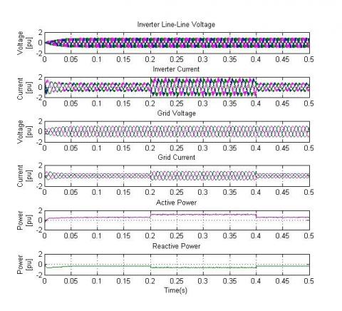
Figure 5 illustrates the waveforms of Inverter voltage & current, Grid voltage & current, Active and Reactive power for all three phase as the result of simulation for static conditions. Here all the quantities are mentioned in p.u instead of actual value. By using DPC-SVM technique the constant switching frequency is obtained and also the rate of reactive power is below zero therefore the instantaneous control is achieved and also the power ripples are very less.
Figure 6 shows the waveforms of Inverter voltage & current, Grid voltage & current, Active and Reactive power for all the three phase as the result of simulation for dynamic conditions. To test the system stability under dynamic conditions the step reference is given at t=0.2 the power is amplified from 0.5 p.u to 1.0 p.u and then reduced to 0.5 p.u at t=0.4.
During these intervals load current follows reference power and track the changes and response time of the system is also very less and the reactive power falls below zero to ensure the instantaneous control and also shows the ability to operate under dynamic conditions by maintaining the voltage regulation.
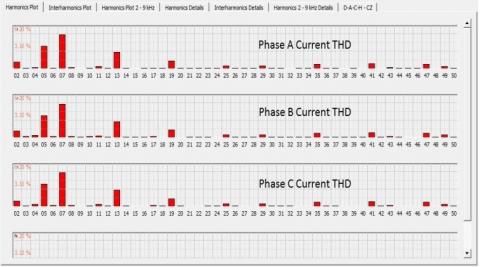
Figure 7 & Figure 8 show harmonic spectrum of grid voltage and grid current respectively. The Total Harmonic Distortion (THD) of voltage and current are 2.78% and 2.80% which are well under 5% and lower order harmonics are also very less as per the IEEE 519-2014 standard.
Table 1. System parameters
|
Parameters |
Value |
|
PV Panel |
250 W |
|
Number of panels connected in series |
2 |
|
Number of panels connected in parallel |
3 |
|
Boost Inductor |
28uH |
|
Boost Capacitor |
1100uF |
|
Capacitor |
2200uF |
|
Filter Inductance |
3.56mH |
|
Filter Capacitance |
50uF |
|
Line Inductance |
40uH |
|
Line Resistor |
0.5Ω |
|
Grid Voltage |
415 V |
|
Switching Frequency |
20kHz |
|
Grid Frequency |
50Hz |
Table 2. PV Panel parameters
|
Parameters |
Value |
|
Rated Power |
250 W |
|
Open Circuit Voltage (Voc) |
37.62 V |
|
Short Circuit Current (Isc) |
8.76 V |
|
Maximum Power Voltage (Vmp) |
29.76 V |
|
Maximum Power Current (Imp) |
8.40 A |
|
Temperature Coefficient of Voc |
- 0.34%/K |
|
Temperature Coefficient of Isc |
+ 0.05%/K |
|
Temperature Coefficient Rated Power |
-0.4%/K |
Figure 4. Simulation waveforms of PV String Voltage, PV String Current, PV String Power and DC link Voltage
Figure 5. Simulation waveforms of Inverter Line-Line Voltage, Inverter Current, Grid Voltage, Grid Current, Active and Reactive Power under static conditions
Figure 6. Simulation waveforms of Inverter Line-Line Voltage, Inverter Current, Grid Voltage, Grid Current, Active and Reactive Power under dynamic conditions
Figure 7. Simulated grid voltage and their spectrum
Figure 8. Simulated grid current and their spectrum
A lab scale prototype of 4.5kW multistring multilevel inverter was developed in the laboratory in order to validate the system. The experimental parameters are as same as used for simulation except load, because for testing purpose the load bank which are available in the laboratory are used. The experimental setup of the proposed system is displayed in Figure 9 which consists of PV source, dSPACE DS1103, gate driver board, Boost converter, multilevel inverter, Resistive inductive load bank, Digital Signal Oscilloscope (DSO) and power quality analyzer (PQ-Box 200).
The PV panels are arranged in the form of string, which are installed in the rooftop is shown in Figure 10. The 10 sq.mm DC cables are used to carry the source from rooftop to laboratory, from where it is delivered to the converters through the Miniature Circuit Breaker (MCB).
dSPACE DS1103 is used as the control interface to realize the real time implementation of the system. The gate pulses for the switches have been given through the gate drive board which consists of optoisolator to isolate the switches and the control signals. Semikron SKM100GB12T4 power modules are used as the switches for the boost converter and the H-bridge inverters. PQ-Box 200 is used to measure and record voltage, current and power. In addition to that, it also able to perform the fault recorder function, Load calculation analysis, ripple control analysis and transient analysis as per the EN50160 and IEC61000-2-2 standards for the low voltage and medium voltage networks.
The voltage and current generated by PV string1 is shown in Figure 11. The voltage generated by the string is around 67 V is nearly equal to the maximum voltage as per the specification listed in Table. But there is a huge difference in the generated current value because of two reasons. One reason is due to the losses in DC cables where it is flown from roof top to the laboratory around 180m and the other reason is due to the amount of load applied.
For testing purpose load banks available in the laboratory are utilized therefore the value of the generated current is reduced to 7.8 A therefore the power generated from the PV string is also reduced from 1500 W to 550 W.
Figure 12 shows DC link voltage of Phase A where voltage is distorted due to the changes in the atmospheric conditions in real time and the generated voltage is around 140 V. P&O MPPT algorithm is used to track the operating point where the voltage is sensed through LV 25-P differential transducer and the current is sensed through LA 55-P current transducer.
Figure 9. Experimental prototype setup in laboratory
Figure 10. Solar panels installed in rooftop
Figure 11. Experimental PV string voltage and current of phase A
Figure 12. Experimental DC link voltage of phase A
Figure 13. Experimental Line-Line Voltage (50 V/div) and Current (1 A/div)
Figure 14. Experimental current harmonic spectrum
Figure 15. Experimental active and reactive power in [p.u]
The sensed signals are given to the ADC channels in dSPACE where the control algorithm is built and the duty signal is generated through the Master bit I/O channels. Then the signals are delivered to the corresponding switches through the gate driver board.
The voltage and the current generated by the inverter for all the three phases are shown in Figure 13 and it is recorded using PQ-Box 200. The generated Line-Line voltage is around 205 V and the current is around 5.8 A, but all the values are expressed in p.u.
The waveforms clearly the synchronization between the three phase and also has phase lag in current waveform due to RL Load. The current waveform is slightly distorted but it follows the pattern of sinusoidal waveform.
The harmonic plot for the current is shown in Figure 14. The harmonic plot is plotted for 2 – 9 kHz upto the harmonic order of fifty. The plot is shown as per the EN50160 and IEC61000-2-2 standard which is the inbuilt standard in PQ-Box 200.
The Active and reactive power plot is shown in Figure 15. By using the SVM-DPC technique the instantaneous control of power is obtained. The Active power P is maintained at 0.8 p.u and the reactive power Q has been maintained at -0.5 p.u to ensure the instantaneous control. The waveform shows no ripple but actually the ripples are present in the active and reactive power. It is not presented here because the plots are shown using timing diagram.
In this paper, the instantaneous control of active and reactive power using DPC strategy for Multilevel Multistring Inverter fed PV system has been presented. The DC link voltages have been controlled independently by using distributed MPPT algorithm which increases the power delivered by the PV system. The SVM based DPC approach has been implemented in the system in stationary reference frame to ensure the constant switching frequency has been maintained and the reduced power ripple has been achieved. The simulation has been done for steady state conditions and for dynamic conditions a step response is introduced in power to test the proposed approach ability to perform in various conditions. The prototype of the proposed system has been developed in the laboratory and verified with the control scheme to maximize the power produced by PV system and results are expressed in terms of p.u. Thus, with the help of experimental prototype results and simulation results the system has been validated as the proof of concept.
This work has been supported by the Department of Science and Technology (DST), Government of India, Project no. DST/TSG/NTS/2013/59.
[1] Kouro, S., Malinowski, M., Gopakumar, K. (2010). Recent advances and industrial applications of multilevel converters. IEEE Trans. Ind. Elect., 57(8): 2553-2580. https://doi.org/10.1109/TIE.2010.2049719
[2] Xiao, B.L., Hang, L.J., Mei, J., Riley, C., Tolbert, L.M., Ozpineci, B. (2015). Modular cascaded H-Bridge multilevel PV inverter with distributed MPPT for grid-connected applications. IEEE Trans. Ind. Appl., 51(2): 1722-1731. https://doi.org/10.1109/TIA.2014.2354396
[3] Riviera, S., Kouro, B., Alepuz, M.M., Rodriguez, C.P. (2014). Multilevel direct power control—a generalized approach for grid-tied multilevel converter applications. IEEE Trans. Power Electron., 29(10): 5592-5604.
[4] Alonso-Martinez, J., Eloy-Garcia, J., Arnaltes, S. (2010). Direct power control of grid connected PV systems with three level NPC inverter. Solar Energy, 84(7): 1175-1186. https://doi.org/10.1016/j.solener.2010.03.023
[5] Hu, J.F., Zhu, J.G., Dorell, D.G. (2014). In-depth study of direct power control strategies for power converters. IET Power Electron., 7(7): 1810-1820. https://doi.org/10.1049/iet-pel.2013.0632
[6] Gui, Y., Kim, C., Chung, C.C., Guerrero, J.M., Guan, Y., Vasquez, J.C. (2018). Improved direct power control for grid-connected voltage source converters. IEEE Trans. Ind. Appl., 65(10): 8041-8051. https://doi.org/10.1109/TIE.2018.2801835
[7] Nian, H., Song, Y. (2014). Direct power control of doubly fed induction generator under distorted grid voltage. IEEE Trans. Power Electron., 29(2): 894-905. https://doi.org/10.1109/TPEL.2013.2258943
[8] Nian, H., Shen, Y.B., Yang, H.Y., Quan, Y. (2015). Flexible grid connection technique of voltage-source inverter under unbalanced grid conditions based on direct power control. IEEE Trans. Ind. Appl., 51(5): 4041-4050. https://doi.org/10.1109/TIA.2015.2428219
[9] Kazemi, M.V., Yazdankhah, A.S., Kojabadi, H.M. (2010). Direct power control of DFIG based on discrete space vector modulation. Ren. Energy, 35: 1033-1042. https://doi.org/10.1016/j.renene.2009.09.008
[10] Zhang, Y.C., Long, J.T., Zhang, Y.C., Lu, T. (2013). TABLE-BASED direct power control for three-level neutral point-clamped pulse-width modulated rectifier. IET Power Electron., 6(8): 1555-1562. https://doi.org/10.1049/iet-pel.2012.0431
[11] Monfared, M., Sanatkar, M., Golestan, S. (2012). Direct active and reactive power control of single-phase grid-tie converters. IET Power Electron., 5(8): 1544-1550. https://doi.org/10.1049/iet-pel.2012.0131
[12] Tsengenes, G., Adamidis, G. (2011). A multi-function grid connected PV system with three level NPC inverter and voltage oriented control. Sol. Energy, 85: 2595-2610. https://doi.org/10.1016/j.solener.2011.07.017
[13] Brando, G., Dannier, A., Pizzo, A.D., Noia, L.P.D., Spina, I. (2015). Quick and high performance direct power control for multilevel voltage source rectifiers. Elect. Power System Res., 121: 152-169. https://doi.org/10.1016/j.epsr.2014.12.008
[14] Zhang, Y., Xie, W., Zhang, Y. (2013). Deadbeat direct power control of three-phase pulse-width modulation rectifiers. IET Power Electron., 7(6): 1340-1346. https://doi.org/10.1049/iet-pel.2013.0563
[15] Cirrincione, M., Pucci, M., Vitale, G. (2011). Direct power control of three-phase VSIs for the minimization of common-mode emissions in distributed generation systems. Elect. Power System Res., 81: 830-839.
[16] Ma, J.P., Song, W.S., Jiao, S.L., Zhao, J.H., Feng, X.H. (2016). Power calculation for direct power control of single-phase three-level rectifiers without phase-locked loop. IEEE Trans. Ind. Electron., 63(5): 2871-2882. https://doi.org/10.1109/TIE.2016.2516959
[17] Song, Z.F., Tian, Y.J., Zhuo, Y., Chen, Z. (2016). Direct power control for three-phase two-level voltage-source rectifiers based on extended-state observation. IEEE Trans. Ind. Electron., 63(7): 4593-4603. https://doi.org/10.1109/TIE.2016.2547859
[18] Zhang, Y., Li, Z.X., Zhang, Y.C., Xie, W., Piao, Z., Hu, C.B. (2013). Performance improvement of direct power control of PWM rectifier with simple calculation. IEEE Trans. power Electron., 28(7): 3428-3437. https://doi.org/10.1109/TPEL.2012.2222050
[19] Cheng, P., Nian, H. (2015). Direct power control of voltage source inverter in a virtual synchronous reference frame during frequency variation and network unbalance. IET Power Electron., 9(3): 502-511. https://doi.org/10.1049/iet-pel.2015.0219
[20] Cho, Y., Lee, K.B. (2016). Virtual-flux-based predictive direct power control of three-phase PWM rectifiers with fast dynamic response. IEEE Trans. Power Electron., 31(4): 3348-3359. https://doi.org/10.1109/TPEL.2015.2453129
[21] Restrepo, J.A., Aller, J.M., Viola, J.C., Bueno, A., Habetler, T.G. (2009). Optimum space vector computation technique for direct power control. IEEE Trans. Power Electron., 24(6): 1637-1645.
[22] Zhou, G., Wu, B., Xu, D. (2007). Direct power control of a multilevel inverter based active power filter. Elect. Power System Res., 77(3-4): 284-294. https://doi.org/10.1016/j.epsr.2006.03.005
[23] Tao, Y.K., Wu, Q.H., Wang, L., Tang, W.H., Wang, L. (2015). Voltage sensorless predictive direct power control of three-phase PWM converters. IET Power Electron., 9(5): 1009-1018. https://doi.org/10.1049/iet-pel.2014.0713
[24] Malinowski, M., Jasinski, M., Kazmeirkowski, M.P. (2004). Simple direct power control of three-phase pwm rectifier using space-vector modulation (DPC-SVM). IEEE Trans. Ind. Elect., 51(2): 447-454. https://doi.org/10.1080/09398368.2003.11463529
[25] Serpa, L.A., Ponnaluri, S., Barbosa, P.M., Kolar, J.W. (2007). A modified direct power control strategy allowing the connection of three-phase inverters to the grid through LCL filters. IEEE Trans. Ind. Appl., 43(5): 1388-1400. https://doi.org/10.1109/TIA.2007.904438
[26] Larrinaga, S.A., Vidal, M.A.R., Oyarbide, E., Apraiz, J.R.T. (2007). Predictive control strategy for DC/AC converters based on direct power control. IEEE Trans. Ind. Electron., 54(3): 1261-1271. https://doi.org/10.1109/TIE.2007.893162
[27] Vazquez, S., Sanchez, J.A., Carrasco, J.M., Leon, J.I., Galvan, E. (2008). A model-based direct power control for three-phase power converters. IEEE Trans. Ind. Electron., 55(4): 1647-1657. https://doi.org/10.1109/TIE.2008.917113
[28] Abad, G., Rodriguez, M.A., Poza, J. (2008). Two-level VSC-based predictive direct power control of the doubly fed induction machine with reduced power ripple at low constant switching frequency. IEEE Trans. Energy Conv., 23(2): 570-580. https://doi.org/10.1109/TEC.2007.914167
[29] Cortes, P., Wilson, A., Kouro, S., Rodriguez, J., Abu-Rub, H. (2010). Model predictive control of multilevel cascaded H-bridge inverters. IEEE Trans. Ind. Electron., 57(8): 2691-2699. https://doi.org/10.1109/TIE.2010.2041733
[30] Bouafia, A., Gaubert, J.P., Krim, F. (2010). Predictive direct power control of three-phase pulse width modulation (PWM) rectifier using space-vector modulation (SVM). IEEE Trans. Power Electron., 25(1): 228-236. https://doi.org/10.1109/TPEL.2009.2028731
[31] Portillo, R., Vazquez, S., Leon, J.I., Prats, M.M., Franquelo, L.G. (2013). Model based adaptive direct power control for three-level NPC converters. IEEE Trans. Ind. Inf., 9(2): 1148-1157.
[32] Hu, J., Zhu, J., Dorrell, D.G. (2015). Model predictive control of grid-connected inverters for PV Systems with flexible power regulation and switching frequency reduction. IEEE Trans. Ind. Electron., 51(1): 587-594. https://doi.org/10.1109/TIA.2014.2328785
[33] Scoltock, J., Geyer, T., Madawala, U.K. (2015). Model predictive direct power control for grid-connected NPC converters. IEEE Trans. Ind. Electron., 62(9): 5319-5328. https://doi.org/10.1109/TIE.2015.2410259
[34] Fang, H., Zhang, Z.B., Feng, X.Y., Kennel, R. (2016). Ripple-reduced model predictive direct power control for active front-end power converters with extended switching vectors and time-optimised control. IET Power Electron., 9(9): 1914-1923. https://doi.org/0.1049/iet-pel.2015.0857