Arckarakit Chaithanakulwat* | Nuttee Thungsuk | Teerawut Savangboon | Sakdawut Boontua | Papol Sardyoung
© 2021 IIETA. This article is published by IIETA and is licensed under the CC BY 4.0 license (http://creativecommons.org/licenses/by/4.0/).
OPEN ACCESS
This paper presents the control of grid-connected single-phase inverters with vector control technology based on the D-Q spindle reference frame for photovoltaic systems. This method begins with converting the grid current of the reference sinusoidal signal to a 90-degree phase angle and converting it to a DC signal using the clack conversion principle. The aim of this research is to control the current amount of the D-axis vector and adjust the motion angle lag and lead the Q-axis vector. This mechanism control technology uses a microcontroller TMS3020F28379D This allows control of the inverter modulation to supply active and reactive power to the grid. As a result, the power factor in the system can be controlled close to unity. The simulation results using MATLAB / Simulink, compared to the prototype mechanism can confirm satisfactory accuracy.
pulse width modulation, photovoltaic systems, voltage control, reactive power control, prototype mechanism, D-Q spindle, grid system, vector control
The impact of fossil energy use in Thailand and other countries are increasing, causing massive environmental destruction and ecological changes, resulting in climate change in each region of the world. Today, in every sector of organizations around the world, it is accelerating to explore new renewable energy sources as well as developing mechanisms to apply even more to renewable energy such as solar, wind, etc. The renewable energy that has been discovered and around the world is accelerating its development is photovoltaic power generation because of its obvious advantages. Over the years, however, researchers have developed a highly efficient prototype mechanism to allow photovoltaic power generation to connect a large number of grids. Forecasts by the International Energy Agency (IEA) are likely to show that within the next five years, solar cell capacity and installation capacity will increase by more than 50% all over the world.
Notwithstanding, in Thailand, photovoltaic systems can provide grid-connected power for both single-phase and three-phase systems. Public and private agencies mobilize researchers and experts in collaboration with universities both within and outside the country, expediting the development of mechanisms to enable power transmission from photovoltaic cells to be able to transmit power efficiently for domestic energy security. In this research paper, experts from various universities have joint research and focus on the method to develop a mechanism for converting DC voltage to AC voltage by using an inverter modulation technique with DQ vector control technology. The controlling principle of this mechanism uses an optimization method that can control the current of the D-axis vector based on the DQ-axis reference system and adjust the motion angle according to the lagging and leading of the Q-axis vector. For the modulation control technology of the inverter, it is controlled with a TMS3020F28379D microcontroller. This inverter controls the distribution of active and reactive power to the grid, resulting in almost unity of the power factor in the system. The process of building and testing the prototype mechanism is discussed in the next section.
Energy control both active accordingly reactive of single-phase voltage source inverter (VSI) for grid-connected photovoltaic systems. The proposed method is to control the vector of energy by separating the active accordingly reactive current control to enter the active accordingly reactive current energy into the grid. The objective is to control the power factor at the grid and improve the overall efficiency of the solar power transfer to convert AC power into the grid and reduce the current distortion of the single-phase voltage source inverter. Nevertheless, the results of the system simulation using MATLAB/Simulink software show that the grid input power factor of the grid is nearly unity. The distortion of the system current decreases, resulting in a total harmonic distortion of 5% [1, 2]. Synchronous D-Q frame controllers are recognized because of their high efficiency compared to stationary α-β frames while working with DC quantities causing zero constant errors. In a single-phase system, the D-Q controller using PI cannot be used directly, because the number of input signals is reduced compared to a three-phase system. The method in a single-phase system is to create a signal perpendicular to the base signal of the system in order to obtain DC quantity by converting α-β to D-Q witch components of orthogonal methods. The basic the release of such delay in the system will reduce the dynamic response which will slow down accordingly sway. Nevertheless, using a D-Q controller that does not need to create a perpendicular phase signal makes it easier to operate [3-9]. The current control scheme for the inverter with a D-Q frame connecting to a single-phase grid, signal blocks are required orthogonal (OSQ) to create a perpendicular virtual signal. This OSG block will make the control system more complex accordingly more distracting, resulting in decreased performance. The current controller based on the D-Q frame can be simplified using the OSG method, which does not change the control circuit in any loop [10-13]. D-Q current controller design the frame for a single-phase inverter is a challenging task, as there is only one real current signal in the circuit, so it is necessary to create an orthogonal signal block to create a virtual orthogonal signal.
Nevertheless, AC variable can be changed to equivalent DC variable via α-β/d-q transformations. However, the OSG block complicates the control system and causes temporary distractions and decreased dynamic performance. The method for creating reference currents using OSG includes the analysis of the d-q axes fragment controller, which is widely discussed for a three-phase system but is often ignored for a single-phase system. The two techniques of separation are referenced-current feed-forward control and the quasi-complex vector proportional – Integrator control is used and analyzed [14]. The two-step inverter control topology for photovoltaic applications connected to a single-phase grid is reliable and works well. In general, the second step converts solar energy into alternating current, while the first step uses an increase in photovoltaic voltage when tracking the highest energy points. This configuration typically uses a boost/flyback topology of type DC/DC. However, the converter has faults such as low efficiency and limited voltage, due to power loss. The topology that brings a low-voltage photovoltaic panel that can be connected to the power grid via an inverter using a DC/DC high-gain converter, which has a special feature of controlling current continuously with an AC controller module, resulting in poor control performance due to the gain at the desired frequency. The plug-in duplication control is therefore used to achieve lower total distortion (THDs) and unity power factor and a low input current THD [15]. D-Q vector control is a powerful technique used in high-performance dynamic inverters. The conversion of AC to DC allows zero steady-state error. Nevertheless, AC currents accordingly voltages with PI controllers can be easily applied to a three-phase inverter, nevertheless for a single-phase inverter there are some challenges. The orthogonal (β) required for rotating frame motion is created by the real sliding phase (α), by one-quarter of a line cycle which reduces the dynamic response. Consequently, the dynamic response concept of a single-phase inverter controlled by a vector controlled by the simulation of an orthogonal circuit similar to a three-phase inverter, amplified for working with grid frequencies, can be found in micro-grids [16-19]. The current control methods for inverters connecting single-phase grids to enable and control reactive power. A direct-quadrature (D-Q) synchronous frame reference method can be used for single-phase converters. This method changes the orthogonal pair which consists of the inverter output current accordingly shifts the time of the current from a stationary frame to a rotating frame synchronous with the basic output frequency. Consequently, the current control options that are mentioned will use the constant-state components in the d-q rotated frame as a DC, and PI will be used to control the error to zero [20].
Nevertheless, from the aforementioned literature, there are many different ways to control mechanisms by simulating and implementing them. This research further studied the relevant literature and proposed the design of the prototype mechanism. For controlling single-phase inverters connected to the grid, using inverter voltage regulation principles using PWM signal modulation techniques, the research team focused on inverter controls the distribution of active and reactive power. to the grid, resulting in almost unity of the power factor in the system. A distinctive feature of this research is the current configuration in the DQ control reference frame using solar cells as a source to the inverter, For the control, this inverter is processed using the TMS320K28379D microcontroller to independently adjust the current in the D-axis and adjust the phase angle to lagging and leading on the Q-axis as mentioned above.
In the next section we will discuss Proposed mechanism of single-phase grid-connected inverter for a photovoltaic system, related theories and principles, results of experiments and analysis, as well as their conclusions and applications.
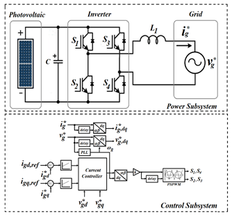
Figure 1 is a prototype mechanism that can be divided into two parts, consisting of a portion of the conductivity of solar cells through a voltage converter mechanism capable of stabilizing the voltage. However, when considering DC-link capacitors they are very important for voltage regulation before being supplied to single phase inverters for grid connection. The second is a vector motion control topology along the D-Q spindle reference frame by converting the grid current to the Clark conversion signal to a phase angle of 90 degrees. Park converter which is equal to the peak of the sinusoidal current fed into the mechanism. For the controller, the PI controls the current according to the specified conditions of the reference frame. The PI controller detects the current to meet the mechanism control conditions to allow the pulse width modulation (PWM) of the inverter device to function for the intended purpose.
Figure 1. Proposed mechanism of single-phase grid-connected inverter for a photovoltaic system
The next section discusses the mathematical principles involved in the research, including D-Q axis transform, the systematic vector control analysis principle, the D-Q axis reference frame transfer function. Notwithstanding, the simulation results are compared with the prototype mechanism produced, in order to verify the results and verify their validity for conclusions and further application.
2.1 Vector control principle with D-Q spindle transformation
Vector transformations are generally applied to three phase induction motors. However, in this research it will be applied to single-phase inverters to control vectors according to the D-Q axis reference frame. This single-phase inverter control is primarily intended to independently control the active and reactive power, which is an advantage of vector control based on the D-Q axis reference frame. This vector coordinate transformation is a variable conversion of voltage and current along the stationary α-β axis reference frame to the D-Q axis reference frame. Likewise, switch from the D-Q axis reference frame to the mobile α-β reference frame, known as Clark's transformation and Clark inverse transform, as shown in Figure 2.
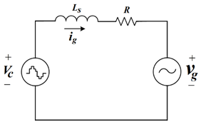
However, considering Figure 3, if Vc is the inverter voltage obtained by converting the photovoltaic DC voltage, Ls and R is the transmission system impedance, Vg is the system voltage grids [21-23]. Analysis of vector control systems for power transmission the grid system can express the equation of the basic system using Kirchhoff's law as Eq. (1).
$-{{V}_{C}}+{{L}_{S}}\cdot \frac{d{{i}_{g}}}{dt}+R{{i}_{g}}+{{V}_{g}}=0$ (1)
Figure 2. Proposed axis conversion for vector control
Figure 3. The equivalent circuit for the transmission of grid systems
Consequently, the inverter voltage will be as:
${{V}_{C}}={{L}_{S}}\cdot \frac{d{{i}_{g}}}{dt}+R{{i}_{g}}+{{V}_{g}}$ (2)
From (2) where ig is the current flowing into the grid system, and write the Laplace transformation equation as:
${{V}_{C}}(S)=s{{L}_{S}}\cdot {{I}_{g}}(S)+R{{i}_{g}}(S)+{{V}_{g}}(S)$ (3)
So the current flowing into the grid system is:
${{I}_{g}}(S)=\frac{1}{(s{{L}_{S}}+R)}\cdot \left( {{V}_{g}}(S)-{{V}_{C}}(S) \right)$ (4)
From Eq. (2), rewrite the time domain form (5)
${{V}_{C}}{{e}^{-j\theta e}}=(s{{L}_{S}}+R)\cdot {{i}_{g}}{{e}^{-j\theta e}}+{{V}_{g}}{{e}^{-j\theta e}}$ (5)
When considered in the expression of $j\theta e$from (5), can be written in the Laplace transform equation as:
${{\vec{V}}_{C}}(S)=R{{I}_{g}}(S)+s{{L}_{S}}{{I}_{g}}(S)+j\omega e{{L}_{S}}{{I}_{g}}(S)+{{V}_{g}}(S)$ (6)
Consider the park's transformation D-Q rotating reference frame as:
$\left[ \begin{align} & \cos \theta \quad \ \ \sin \theta \\ & -\sin \theta \quad \cos \theta \\\end{align} \right]\times {{\vec{V}}_{C}}(S)$ (7)
The conversion of a D-Q axis, the current and voltage converter is displayed in the D-Q reference frame two-axis rotate simultaneously at the specified AC frequency (w) as:
$\left[\begin{array}{l}v_{d, c} \\ v_{q, c}\end{array}\right]=\left[\begin{array}{ll}L_{S}+R & j \omega e L_{S} \\ -j \omega e L_{S} & L_{S}+R\end{array}\right]\left[\begin{array}{l}i_{g} d \\ i_{g} q\end{array}\right]+\left[\begin{array}{l}v_{d, g} \\ v_{q, g}\end{array}\right]$ (8)
Moreover, the voltage equation in the synchronous reference frame D-Q as:
${{V}_{d,c}}=(S{{L}_{S}}+R){{I}_{g}}d-j\omega e{{L}_{S}}{{I}_{S}}q+{{V}_{g}}d$ (9)
${{V}_{q,c}}=(S{{L}_{S}}+R){{I}_{g}}q-j\omega e{{L}_{S}}{{I}_{S}}d+{{V}_{g}}q$ (10)
From the theories and principles mentioned above, when considering the application of D-Q control technology with hysteresis control and others. It was found that the controls were more accurate and resulted in lower losses in switching devices. Likewise, the D-Q control method can be implemented in real time with accurate voltage and current sensing, but the D-Q control has its design drawbacks which are complicated and complicated. Considering Figure 2. fore it, it is found that in the frame rotation, α and β components are required, with zero order components being ignored. Zero order components were ignored as they were balanced components. Based on this principle, this research is applied to energy control by controlling the d-axis component and the reactive power by the q-axis component, as it responds faster compared to other control strategies.
2.2 D-Q spindle reference frame transfer function
The current flow control transfer function within the loop can be done in the D-Q spindle reference frame, which is based on the fundamental relationship of the system model. The control loop consists of a PI controller, which is separated into decoupling factors and feed-forward, can explain the current flow control in the loop by showing the block diagram as shown in Figure 4.
Consider from Figure 4. The equation can be written to the control of PI as:
$R(S)={{K}_{p}}+\frac{{{K}_{i}}}{s}={{K}_{p}}\cdot \left( \frac{1+{{\tau }_{i}}\cdot s}{{{T}_{i}}\cdot s} \right)$ (11)
Figure 4. The block diagram transfer function
Nevertheless, in the case of the proportion of the criteria and the time constant are:
${{T}_{i}}=\frac{{{K}_{p}}}{{{K}_{i}}}$ (12)
From (12) to the specified parameters, then the controlling block of PI as:
$\left( {{I}_{g,ref}}(S)-{{I}_{g}}(S) \right)\left( {{K}_{p}}+\frac{{{K}_{i}}}{S} \right)={{V}_{C}}(S)$ (13)
Considering the PWM converter block, the output voltage is based on the reference signal of the average delay equal to half of the switching circuit due to the switching of VSC. Consequently, write in the equation as:
$Y(S)=\frac{1}{1+{{T}_{a}}\cdot s}$ (14)
From the (14) when, $T_{a}=\frac{T_{s w}}{2}$ consequently, for converting a block as:
$V_{C}^{'}(S)\cdot \frac{1}{(1+s{{T}_{a}})}={{V}_{C}}(S)$ (15)
Moreover, the system transfer function block, from the behaviour of the control system refers to (9) the VSC model equation in a synchronous reference frame with more than one output and more than one input, which is difficult to control [14, 15]. The system equation was therefore rewritten as:
${{v}_{d,c}}-{{v}_{d}}=L\frac{d{{i}_{d}}}{dt}+R{{i}_{d}}-\omega L{{i}_{q}}$ (16)
${{v}_{q,c}}-{{v}_{q}}=L\frac{d{{i}_{q}}}{dt}+R{{i}_{q}}-\omega L{{i}_{d}}$ (17)
The use of internal loop controllers $i_{d}, i_{q}$ and independent isolates. Causes the output of the reference voltage signal of the two axes to feed to the converter, resulting in two references in the system which are the components of D-Q as:
$V_{d,c}^{'}=({{i}_{d,ref}}-{{i}_{d}})\cdot \left( {{K}_{p}}+\frac{{{K}_{i}}}{s} \right)\cdot \frac{1}{(1+s{{T}_{a}})}$ (18)
$V_{q,c}^{'}=({{i}_{d,ref}}-{{i}_{q}})\cdot \left( {{K}_{p}}+\frac{{{K}_{i}}}{s} \right)+\omega L{{i}_{d}}+{{v}_{q}}$ (19)
From (18), substituting (19) and substituting the system equations in (16) and (17) as:
$L\frac{d{{i}_{d}}}{dt}+R{{i}_{d}}={{V}_{d,c}}$ (20)
$L\frac{d{{i}_{q}}}{dt}+R{{i}_{q}}={{V}_{q,c}}$ (21)
Nevertheless, a complete system block diagram can be illustrated in Figure 5.
Figure 5. Complete control block diagram
Figure 5 from the equation of all feedback control systems, it can be mathematically modeled and proportional to the plant in the control system as:
$G(s)=\frac{Y(s)}{U(s)}=\frac{{{I}_{g}}(s)}{{{V}_{c}}(s)}$ (22)
The feedback proportional system of the electrically coupled inductor as:
$G(s)=\frac{1}{R}\ \frac{1}{s\tau +1}$ (23)
where, $\tau $ is the time constant, that is ${Ls}/{R}\;$.
Likewise, the equation of a closed system as:
${{G}_{c,OL}}(s)=kpi\left( \frac{sTii+1}{sTii} \right)\frac{1}{sTa+1}\frac{1}{R}\frac{1}{s\tau +1}$ (24)
Based on the mathematical model of the aforementioned D-Q spindle reference frame transfer function, it can be proved that the control is highly stable compared to the hysteresis control. From the analysis with mathematical and electrical equations it can be seen that control variables can be determined for their intended purpose. In this research, the researchers determined the independent control of active and reactive power to the grid, and this technology could further stabilize the switching frequency conditions. This determination of switching frequencies results in reduced losses from switching devices, which is an advantage mentioned above.
Presenting the literature research and the above-mentioned principles, this research has produced a prototype starting from the design of the control circuit, the power circuit of a single-phase inverter connected to the grid. This prototype consists of a DC voltage capacitor, current filter inductor, IGBT circuit, gate drive circuit, delay circuit, current detection circuit, and a voltage detection circuit. Accordingly, writing commands for processing with the math model function of MATLAB/ Simulink programs into microcontrollers [24-31]. Moreover, active power and reactive power control with vector simplified optimization techniques based on the D-Q spindle reference frame for single-phase grid-connected inverter. The following sections will present the results of the prototype compared to the MATLAB/Simulink program, moreover review the results for further development.
Nevertheless, the following section is a simulation experiment with MATLAB / Simulink, to compare it with the prototype mechanism produced. An experiment for controlling a single-phase grid-connected inverter using a vector control technique based on the D-Q spindle reference frame for photovoltaic systems, consisting of simulating the grid voltage reference sinusoidal signal along the axis reference frame D-Q is compared to the prototype mechanism. Simulate the amplitude control of the current according to the D-axis reference frame supplied to the grid. In addition to the simulation and experiment of the current amplitude control reference frame of the D-axis supplied to the grid, details are given below.
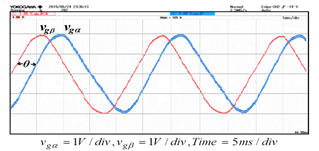
Figures 6 (a) and (b) show the use of a vector control technique based on the D-Q spindle reference frame of a single-phase grid. Performing a transformation in the form of a Clark shift that adjusts the angle of the lagging motion voltage equal to 90 degrees, can be confirmed in principle. Likewise, Figures 7 (a) and (b), when transformed in the Park's transformation model using the magnitude of the reference sine voltage and modulating the PI controlled current, the principle can be confirmed as a principle and purpose.
(a)
(b)
Figure 6. Grid reference voltage signal on Clark’s transformation axis
(a)
(b)
Figure 7. Grid reference voltage signal on Park’s Transformation axis
(a)
(b)
(c)
(d)
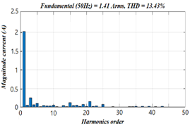
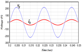
Figure 8. The control of grid currents by specifying the reference current D-axis
Figure 8 (a) simulates grid current control by assigning the reference current of the D-axis equal to 2-A. accordingly, Figure 8 (b) the Total harmonic distortion (THD) is 13.20%. Furthermore, from Figures 8 (c) and (d), when testing the prototype compared to the simulation, THD values the increase to 13.43%, but also found that the third harmonic and fifth harmonic trends persisted due to the loss of the IGBT switch in the inverter.
(a)
(b)
(c)
(d)
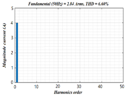
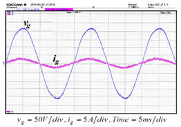
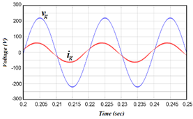
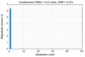
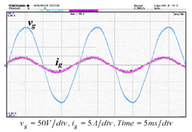
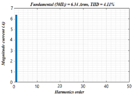
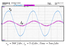
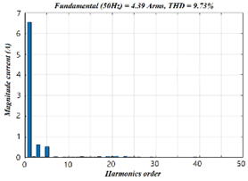
Figure 9. Increasing the reference current of the D-axis
Consider from Figure 9 (a) and harmonic spectrum. Figure 9 (b) when adding the reference current of the D-axis to 4-A, the simulation and comparison with the prototype, it is found that if the current increases, it will cause changes in the good direction. Nevertheless, considering the prototype, it is found that the spectrum of THD is reduced to 9.74%, as shown in Figure 9 (c) and (d). Moreover, it is also found that the harmonic spectrum, third and fifth-order, fell to satisfactory.
(a)
(b)
(c)
(d)
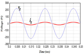
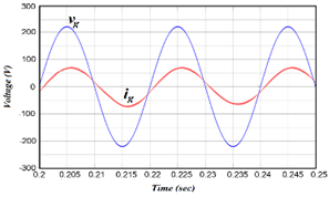
Figure 10. The grid current leading to the grid voltage and harmonic spectrum
The topics presented here are the current control of the Q-axis reference frame, which is the reference axis of the angle between the voltage and current of the grid. Consider from Figures 10 (a), and (c) that the current of the Q-axis reference frame can be adjusted for objective purposes with a positive value and that the current of the D-axis reference frame is constant and greater. The simulation results show that the grid current leading to the grid voltage. Moreover, when determining that the Q-axis current is negative, it is found that the grid current lagging on the grid voltage. Figures 10 (b) and (d) is the harmonic spectrum of the grid currents when the leading and lagging occurs are found, the effects of microcontrollers are controlled TMS320k28379D of the corresponding prototype, the results are satisfactory.
Moreover, Figure 11 (a) and (c) when determining that the Q-axis current is negative, it is found that the grid current lagging on the grid voltage. Figure 11 (b) and (d) harmonic spectrum, the results are satisfactory.
Figures 12 (a) and (b) this section presents the efficiency of the control mechanism of the prototype compared to the simulation with sudden changes from 2-A to 6-A.
(a)
(b)
(c)
(d)
Figure 11. The grid current lagging to the grid voltage and harmonic spectrum
It was found that the response of the mechanism was satisfactory. Moreover, when the grid currents controlled by the currents along the D-axis reference frame with the currents along the Q-axis reference frame equal to zero, accordingly the angle between the voltage and currents of the grid is equal to zero finds that the power factor is nearly unity.
(a)
(b)
(c)
(d)
Figure 12. Performance testing of microcontroller prototypes
Moreover, Figures 12 (c) and (d) if the current decrease from 6-A to 2-A in a sudden, the control mechanism can still be satisfactorily controlled and can also control the modulation of the inverter to supply active and reactive power to the grid.
The simulation results compared with the prototype, it is found that the vector current control technique based on the D-Q axis reference frame of the grid single phase, when converting in the form of Clark's transformation at the angle of both grid voltages lagging together 90-degree, can confirm the accuracy according to moreover principle, grid current control simulation by determining reference D-axis with 2-A posture compared to the prototype were consistent and also showed that the harmonic order the third and fifth remains the system, because of the switch IGBT. Nevertheless, when adding the reference current of the D-axis to 4-A found that when the current increased, it was able to eliminate the third harmonic, fifth order to be reduced as well. For control, according to the Q-axis reference frame, which is the reference axis of the angle between the voltage and current in the grid. The comparison results show that from the grid current prototype, the grid voltage and the harmonics of the grid when the leading is less than the grid current lagging. Because of the optimized D-Q vector control, the TMS320K28379D microcontroller of the prototype is still unstable, nevertheless, when comparing the overall it is acceptable.
However, the research has many flaws, the researchers recommend if someone is interested in applying it to other types of energy systems. The vector control of the D-Q spindle reference frame only calculated the amplitude current in a fundamental frequency system at 50HZ, in the experiment of supplying current to a continuous system with a non-linear load connected to the same system. This causes other low-frequency harmonic currents to be interpolated in the low-magnitude portion of the reference current. Finally, if interested parties should be careful of the output voltage noise of the inverter circuit, such noise is quite large, the design should add a snubber circuit to reduce the interference in this section.
The author would like to thank Thonburi Rajabhat University, Thailand. That provide support for laboratories and tools for research work. In addition, thank you Mr. Borirat Imyaem, a research assistant who provided technical assistance and collection of experimental results.
|
AC |
Alternating current |
|
DC |
Direct current |
|
D-Q |
Vector of D-Q axis |
|
IGBT |
Isolate Gate Bipolar Transistor |
|
PSPWM |
Phase-shift pulse width modulation |
|
THD |
Harmonic Distortion |
|
VSI |
Voltage source inverter |
|
Ig |
Grid current |
|
vg |
Grid voltage |
|
ig,d |
Grid current of D-axis |
|
ig,q |
Grid current of Q-axis |
|
ig,dq |
Grid current of dq-axis |
|
vg,dq |
Grid voltage of dq-axis |
|
$\mathcal{V}_{g, \infty}$ |
Grid voltage of $\infty$-axis |
|
$v_{g, \beta}$ |
Grid voltage of $\beta$-axis |
|
VC |
Voltage of converter |
|
iref |
Reference current |
[1] Samerchur, S., Premrudeepreechacharn, S., Kumsuwun, Y., Higuchi, K. (2011). Power control of single-phase voltage source inverter for grid-connected photovoltaic systems. IEEE/PES Power Systems Conference and Exposition (PSCE), Phoenix, AZ, USA, pp. 1-6. https://doi.org/10.1109/PSCE.2011.5772504
[2] Zmood, D.N., Holmes, D.G. (1999). Stationary frame current regulation of PWM inverters with zero steady-state error. IEEE Trans. Power. Electron., 18(3): 814-822. https://doi.org/10.1109/PSCE.2011.5772504
[3] Mnider, A.M., Atkinson, D.J., Dahidah, M., Armstrong, M. (2016). A simplified DQ controller for single-phase grid-connected PV inverters. 7th International Renewable Energy Congress (IREC), Hammamet, Tunisia, pp. 1-6. https://doi.org/10.1109/IREC.2016.7478941
[4] Li, B., Huang, S., Chen, X., Xiang, Y. (2017). A simplified DQ-frame current controller for single-phase grid-connected inverters with LCL filters. In 2017 20th International Conference on Electrical Machines and Systems (ICEMS), pp. 1-5. https://doi.org/10.1109/ICEMS.2017.8056053
[5] Bassey, O., Chen, B., Butler-Purry, K.L. (2018). Sequential service restoration in distribution systems and microgrids integrating frequency response and varying switching interval. In 2018 IEEE Texas Power and Energy Conference (TPEC), pp. 1-6. https://doi.org/10.1109/TPEC.2018.8312077
[6] Bassey, O., Butler-Purry, K.L. (2019). Modeling single-phase PQ inverter for unbalanced power dispatch in islanded microgrid. In 2019 IEEE Texas Power and Energy Conference (TPEC), pp. 1-6. https://doi.org/10.13140/RG.2.2.25908.50566
[7] Weise, N. (2015). Implementation and validation of DQ current control of a bidirectional sic single-phase AC-DC converter. In 2015 IEEE Applied Power Electronics Conference and Exposition (APEC), pp. 3143-3149. https://doi.org/10.1109/APEC.2015.7104801
[8] Baier, C.R., Torres, M., Muñoz, J.A., Mauricio, J.M., Rohten, J., Rivera, M. (2015). Nonlinear control strategy for current source cascaded H-bridge inverters an approach considering single-phase DQ components. In 2015 IEEE International Conference on Industrial Technology (ICIT), pp. 3079-3084. https://doi.org/10.1109/ICIT.2015.7125553
[9] Bahrani, B., Rufer, A., Kenzelmann, S., Lopes, L. (2011). Vector control of single-phase voltage-source converters based on fictive-axis emulation. IEEE Trans. Ind. Appl., 47(2): 831-840. https://doi.org/10.1109/TIA.2010.210199
[10] Li, B., Huang, S., Chen, X., Xiang, Y. (2017). A simplified DQ-frame current controller for single-phase grid-connected inverters with LCL filters. 20th International Conference on Electrical Machines and Systems (ICEMS), Sydney, NSW, pp. 1-5. https://doi.org/10.1109/ICEMS.2017.8056053
[11] Gou, B., Ge, X., Wang, S., Feng, X., Kuo, J.B., Habetler, T.G. (2015). An open-switch fault diagnosis method for single-phase PWM rectifier using a model- based approach in high-speed railway electrical traction drive system. IEEE Transactions on Power Electronics, 31(5): 3816-3826. https://doi.org/10.1109/TPEL.2017.2691804
[12] Zeng, Z., Yang, H., Zhao, R., Cheng, C. (2013). Topologies and control strategies of multi-functional grid-connected inverters for power quality enhancement: A comprehensive review. Renewable and Sustainable Energy Reviews, 24: 223-270. https://doi.org/10.1016/j.rser.2013.03.033
[13] Choi, W., Morris, C., Sarlioglu, B. (2016). Modeling three-phase grid-connected inverter system using complex vector in synchronous DQ reference frame and analysis on the influence of tuning parameters of synchronous frame PI controller. In 2016 IEEE Power and Energy Conference at Illinois (PECI), pp. 1-8. https://doi.org/ 10.1109/PECI.2016.7459235
[14] Li, B., Huang, S., Chen, X., Wan, S. (2018). Enhanced DQ current control for single-phase voltage-source inverters. IET Power Electronics, 11(9): 1537-1546. https://doi.org/10.1049/iet-pel.2017.0747
[15] Evran, F. (2017). Plug-in repetitive control of single-phase grid-connected inverter for AC module applications. IET Power Electronics, 10(1): 47-58. https://doi.org/10.1049/iet-pel.2015.0950
[16] Ninad, N.A., Lopes, L.A.C. (2012). A vector-controlled single-phase voltage source inverter based grid interface suitable for variable frequency operation in autonomous microgrids. Electric Power Components and Systems, 40(11): 1266-1284. https://doi.org/10.1080/15325008.2012.689416
[17] Patsalides, M., Efthymiou, V., Stavrou, A., Georghiou, G.E. (2016). A generic transient PV system model for power quality studies. Renewable Energy, 89: 526-542. https://doi.org/10.1016/j.renene.2015.12.003
[18] Iffouzar, K., Benkhoris, M.F., Aouzellag, H., Ghedamsi, K., Aouzellag, D. (2019). Behaviour of a six phase induction motor fed by multilevel inverter. International Journal of Computer Aided Engineering and Technology, 11(3): 283-304. https://doi.org/10.1109/INTEE.2015.7416779
[19] Crowhurst, B., El-Saadany, E.F., El Chaar, L., Lamont, L.A. (2010). Single-phase grid-tie inverter control using DQ transform for active and reactive load power compensation. IEEE International conference on Power and Energy, Kuala Lumpur, Malaysia. pp. 489-494. https://doi.org/10.1109/PECON.2010.5697632
[20] Blaabjerg, F., Teodorescu, R., Liserre, M., Timbus, A. (2006). Overview of control and grid synchronization for distributed power generation systems. IEEE Transactions on Industrial Electronics, 53(5): 1398-1409. https://doi.org/10.1109/TIE.2006.881997
[21] Teodorescu, R., Blaabjerg, F., Borup, U., Liserre, M. (2004). A new control structure for grid-connected LCL PV inverters with zero steady-state error and selective harmonic compensation. In Nineteenth Annual IEEE Applied Power Electronics Conference and Exposition, 2004. APEC'04., 1: 580-586. https://doi.org/10.1109/APEC.2004.1295865
[22] Chaithanakulwat, A., Kinnares, V., Thungsuk, N. (2012). Single-phase grid-connected photovoltaic system with active power filter functionality. In 2012 15th International Conference on Electrical Machines and System (ICEMS), Sapporo, pp. 175-177. https://doi.org/10.1109/icems.2013.6713323
[23] Chaithanakulwat, A., Kinnares, V. (2017). Implementation of a low-cost single-phase grid-connected photovoltaic system with active filtering mechanism. International Review of Electrical Engineering (IREE), 12(2): 175-182. https://doi.org/10.15866/iree.v12i2.11383
[24] Chaithanakulwat, A. (2019). Track the maximum power of a photovoltaic to control a cascade five-level inverter a single-phase grid-connected with a fuzzy logic control. International Journal of Power Electronics and Drive System (IJPEDS), 10(4): 1863-1874. https://doi.org/10.11591/ijpeds.v10.i4
[25] Raja Mohamed, S., Aruna Jeyanthy, P., Devaraj, D. (2018). Hysteresis-based voltage and current control techniques for grid connected solar photovoltaic systems: comparative study. International Journal of Electrical and Computer Engineering (IJECE), 8(1): 2671-2681. https://doi.org/10.11591/ijece.v8i5
[26] Chandra Shekar, S., Ravi Kumar, G., Lalitha, S.V.N.L. (2019). A transient current based micro-grid connected power system protection scheme using wavelet approach. International Journal of Electrical and Computer Engineering (IJECE), 9(1): 14-22. https://doi.org/10.11591/ijece.v9i1.pp14-22
[27] Chaithanakulwat, A. (2020). Optimization of shunt active power filtering with pi control in a three-phase three wire system. European Journal of Electrical Engineering, 22(1): 39-47. https://doi.org/10.18280/ejee.220105
[28] Chaithanakulwat, A. (2019). Design of solar-powered aeration system for shrimp ponds of farmers in Thailand. European Journal of Electrical Engineering, 21(6): 539-546. https://doi.org/10.18280/ejee.210608
[29] Chaithanakulwat, A. (2020). Development of DC voltage control from wind turbines using proportions and integrals for Three-phase grid-connected inverters. International Journal of Electrical and Computer Engineering (IJECE), 10(2): 1701-1711. https://doi.org/10.11591/ijece.v10i2
[30] Zaamouche, F., Saad, S., Hamiche, L. (2020). Discontinuous PWM applied for a three-phase five-level CHB inverter fed by PV solar-boost converter. European Journal of Electrical Engineering, 22(2): 153-161. https://doi.org/10.18280/ejee.220209
[31] Liu, D.D., Zhou, L., Sai, X.Y. (2020). Vector- proportional-integral control of inductor-capacitor- inductor active power filter under the alpha-beta stationary coordinate system. European Journal of Electrical Engineering, 22(1): 79-86. https://doi.org/10.18280/ejee.220110