Badreddine Babes* | Amar Boutaghane | Noureddine Hamouda | Sami Kahla | Ahmed Kellai | Thomas Ellinger | Jürgen Petzoldt
© 2020 IIETA. This article is published by IIETA and is licensed under the CC BY 4.0 license (http://creativecommons.org/licenses/by/4.0/).
OPEN ACCESS
This article aims to improve the permanent magnet DC (PMDC) motor performance for photovoltaic (PV) wire-feeder systems (PVWFSs) of arc welding machines. The considered technique is designed by direct speed control based on optimal Fractional-order Fuzzy PID FO-Fuzzy-PID controller. The purpose is to ensure optimal control of wire feed speed reference to reduce torque ripples and hence, the performance of the WFS is improved. The dynamic reaction of the proposed solar PVWFS relies upon the scaling factors of FO-Fuzzy-PID controller, which are optimized by using teaching-learning algorithm based on Particle Swarm Optimization (PSO) method. The maximum power point tracking (MPPT) is achieved using an intelligent FO-Fuzzy-PID current controller based Perturb and Observe (P&O) MPPT algorithm. The PVWFS system incorporating the proposed method is tested and compared with the conventional PID control scheme under different weather conditions. The simulation of the proposed system by MATLAB\SIMULINK is carried out. The simulation results indicate the effectiveness of the considered control strategy in terms of the reduction in torque oscillations, optimizing electrical power and wire feed speed.
solar photovoltaic (PV) module, wire feeder systems (WFSs), DC-DC buck converter, MPPT control, FO-Fuzzy PID controller, particle swarm optimization (PSO) algorithm
The gas metal arc welding (GMAW) process is commonly utilized in modern welding industry of metal materials, due to its flexibility, rapidity, high efficiency and extensive applications [1]. Its process is characterized by nonlinear, strong time varying and coupling among diverse parameters. During the GMAW process, wire feed rate, which is also the wire feed speed, plays a vital role in determining the weld characteristics, and its value must equal the melting rate of a consumable electrode for stable welding operation [2]. So, the wire-feeder system (WFS) is a fundamental device of the standard GMAW process. A number of welding WFSs have been developed to generate a control signal which controls the wire-feed speed of a consumable electrode or the level of the welding current to prevent weld splatter and arc outage [3]. However, such WFSs are often limited by significant tolerances between motors on comparable spool guns. Such limitations may lead to welding under non-optimal conditions due to wire feed speeds that are outside the optimal range for the given welding operation, owing to the natural tolerances of wire drive motors and related mechanisms. Numerous solutions have been proposed in the literature to improve the wire-feed speed responses of WFSs, either by developing new systems with different types of PMDC motors or by designing robust wire-feeder controllers [4-8].
Now, the modern welding WFSs are generally equipped with a permanent magnet DC motor (PMDC), since this device has some merits such as: a high performance, a big starting torque, a low noise and so on. The PMDC motors provides an attractive other option to AC servo motors in better speed control applications. In addition, PMDC motors are exclusively well known in low-power and high exact servo applications because of their reasonable cost and facility of control.
The perfect design of wire-feeder regulator is important to grant productivity, wide range welding capability, and comfort level to the welder user. One of the most widely utilized wire-feed speed control schemes is the proportional-integral-derivative (PID) regulator [5]. It is a simple and stable regulator that offers a consistent control effort. However, the design of the accurate wire feeder controller for PMDC motor of the WFSs using the traditional PID controller require accurate modeling of the PMDC motor that considers the non-linear dynamics. It is feasible to utilize a traditional PID regulator to manage the wire-feed velocity of WFSs [5]. But, traditional PID regulators do not yield reasonable performance over a wide range of working situations. In other hand, Fractional-order (FO) hybrid fuzzy logic controllers (FLCs) are the results of the mixture of FLCs and fractional-order PID controller. Under such combination, the FLC based on fractional-order PID regulator has a superior performance, stability and robustness than conventional PID controller for a wide range of dynamical systems [9].
The current article investigates the effectiveness of a fractional-fuzzy PDI (FO-Fuzzy-PID) controller at producing better wire feed speed regulation compared to traditional PID controller. Parameter adjustment is a vital step to develop applications with the proposed FO-Fuzzy-PID controller. This method is long and time consuming, since it is generally conducted through trial and error. Therefore, the parameter calibration in FO-Fuzzy-PID controller can be handled by evolutionary optimization techniques. Due to its faster convergence and flexibility, a particle swarm optimization (PSO) method is adopted in this article for the optimal tuning of the proposed FO-Fuzzy-PID controller.
The present work is a part of an ongoing project entitled “Systems and Methods for Wire Feed Speed Control of GMAW Processes”, and principally relates to a direct control of the wire-feed speed and a power supply of the WFSs, which aiming at developing a holistic wire-feeder system that includes a solar photovoltaic (PV) system. In fact, the intelligent MPPT controllers of the solar energy conversion system are a major research issue we are tacking in this project, such that the WFS power supplied by the solar PV system is maximized. There are numerous types of welding power supplies utilized for a variety of welding processes in isolated area. The diesel generators called diesel engine-driven welding machines are utilized for gas metal arc welding (GMAW), shield metal arc welding (SMAW), and gas tungsten arc welding (GTAW), etc., since they are simple to install, but these kinds of power supplies incorporate a diesel fueled engine attached to an electrical generator cause numerous problems such as fuel cost, maintenance, transportation, pollution, noise, and short lifetime. The solar photovoltaic-wire feeder system (PVWFS) presents other solution to replace the used diesel generator in welding power supplies at isolated areas, because it generates electricity without damaging the environment, and they are mostly utilized due to high distribution costs/non-availability of grid-power [1]. According to Errouhaa et al. [10], frequent maintenance and repairs of diesel engine-driven welding machines are regularly 2-4 times more than solar PVWFSs. Therefore, the use of PV system as power supply for welding machines can be considered as one of the most promising areas of solar PV application.
The proposed solar PVWFS system requires only a solar PV module with a switching DC-DC buck converter and a storage bank, which will help in the moment when no insolation or power shortage is presented. Moreover, the proposed system works in isolated areas, which needs an efficient and reliable production system to extract the maximum power from the solar energy under different conditions. The solar PV module coupled directly to the DC-DC switching converter can meet these requirements. In the WFS-side, a DC constant voltage power supply based on a DC-DC buck converter is adopted for a PMDC servo motor. The DC-DC buck converter responds to the requirements of the modern WFSs due to high power handling ability and a better use of the power switch. Furthermore, the problem of identifying the maximum power point (MPP) of solar PV module can be solved by using an intelligent Perturb and Observe (P&O) MPPT algorithm combining fractional-order and fuzzy logic controller.
Compared with the conventional (P&O) PID control technique, the proposed FO-Fuzzy-PID based MPPT controller accelerates the MPPT and avoids deviating from the MPP. The major contribution of this paper is, a maiden application has been made to tune all the possible parameters of FO-Fuzzy-PID based MPPT controller of solar PV module and FO-Fuzzy-PID based speed regulator of PMDC motor, simultaneously with PSO gain tuning mechanism to handle the uncertainties caused by the WFS and the solar PV generator.
In this scope, the present work describes how an operation of solar PVWFS can be achieved. Therefore, based on previous discussions and analysis, the main tasks assigned to the proposed solar PVWFS are:
A permanent tracking of the MPP of PV module under different insolation and temperature conditions, by a proper tuning of the DC-DC buck converter duty cycle, using FO-Fuzzy-PID based MPPT controller.
A global flow of the extracted solar PV power to the WFS, via mechanical speed control of the PMDC motor, in order to match its load-speed characteristics.
In order to investigate the proposed solar PVWFS performances, and prior to numerical simulation, each part of the solar PVWFS is modeled. Simulation results present the effectiveness of the proposed hybrid FO-Fuzzy-PID technique under varied operating conditions. To highlight the advantages of the proposed control scheme a comparative study with conventional (P&O) PID control method and FO-PID speed control scheme is made. Consequently, the present work will be prepared as follows:
The description and modeling of the proposed solar PVWFS will be given in Section 2, in Section 3, an overview of fractional calculus, FO-Fuzzy-PID controller & PSO algorithm will be covered for use with FO-Fuzzy-PID controllers of solar PVWFS, while in Section 4, all the optimized FO-Fuzzy-PID controllers will be detailed. In Section 5, the simulation results of all the optimized FO-Fuzzy-PID controllers will be discussed and results compared to more classical PID control methods.
The proposed solar PVWFS system is depicted in Figure 1. It composed of four main elements: solar PV module, DC-DC buck converter for MPPT, and storage bank (batteries) connected to the WFS of arc welding machine driven by PMDC motor. In this study a DC-DC buck converter is utilized to control the solar PV module current. The control unit is based on the idea of an indirect MPPT control loop. In this manner, the first FO-Fuzzy-PID current loop adjusts the inductor current (IPV) through the change in the duty ratio (d), while the MPPT algorithm tracks the MPP through the change in the reference of inductor current. The reference current is given by an enhanced P&O MPPT algorithm.
Figure 1. Description of the solar photovoltaic powered wire feeder system
A constant DC source is utilized because it simplifies the analysis, giving the possibility of representing solar PV systems with a battery charge or solar PV systems with a second energy conversion stage [11]. The second stage is composed of a DC source connected to the WFS via a second DC-DC power converter. In the speed control loop of WFS, the speed error signal obtained by comparing the real PMDC motor velocity and the reference velocity is driven to the second FO-Fuzzy-PID regulator. Figure 1 shows the schemes of the proposed controllers that will be detailed later.
2.1 Solar PV generator model
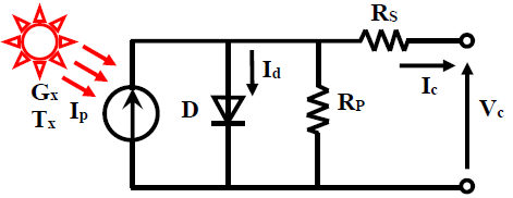
Solar cells are frequently approximated as current generators with dependent voltage sources. Figure 2 illustrates the equivalent circuit of o single solar cell which comprises a single-diode (D), parallel resistor (Rp), and serial resistor (Rs). Resistance Rs denotes an internal resistor to the current flow. By applying kerchief’s current law, the output current of the solar cell is written by [12]:
${{I}_{c}}\,=\,{{I}_{p}}-{{I}_{o}}\left[ \exp \left( A({{V}_{c}}+{{R}_{s}}.{{I}_{c}} \right)-1 \right]-\frac{{{V}_{c}}+{{R}_{s}}.{{I}_{c}}}{{{R}_{p}}}$ (1)
where, Ip is the produced photocurrent (A), Ic is the output current (A), Id is the diode current (A), Vc is the output voltage, I0 is the diode-reverse saturation current (A), A is the ideality factor of the diode (from 1 to 2).
Figure 2. Single solar cell model
Other variables in Eq. (1) can be determined by:
${{I}_{p}}\,={{I}_{sc}}+\,\left[ {{K}_{i}}\left( T-{{T}^{*}} \right) \right]\frac{G}{1000}$ (2)
${{I}_{S}}\,={{I}_{rs}}{{\left( \frac{T}{{{T}^{*}}} \right)}^{3}}\exp \left[ \frac{q.{{E}_{go}}}{{{K}_{o}}.A}\left( \frac{1}{{{T}^{*}}}-\frac{1}{T} \right) \right]$ (3)
${{I}_{rs}}\,=\frac{{{I}_{sc}}}{\exp \left[ \frac{q.{{V}_{oc}}}{{{N}_{c}}.{{K}_{o}}.A.T} \right]-1}$ (4)
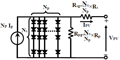
where, T* is the solar cell reference temperature, Irs is the reverse-saturation current at reference temperature, Isc is short circuit current at T* and solar radiation G, Ego is the energy band gap of the photo-diode (Ego =1.12ev) and Ki is the short-circuit temperature coefficient (0.0024 A/K). q is the charge of the electron (1.6 ×10⁻¹⁹ C), Ko is the Boltzmann’s constant (1.38×10⁻²³ J/K), Voc is the solar cell open-circuit voltage and Nc is the number of solar cells. The power generated by a single solar cell is inadequate to drive such solar PVWFS system, then, a group of solar cells are coupled collectively in parallel and in series in the solar PV generator to reach a power, which is capable to run the collection of PMDC motor-WFS at nominal situations. The model of solar PV generator is written by the following relationship [13].
${{I}_{PV}}\,=\,{{I}_{pg}}-{{I}_{og}}.\left[ \exp \left( {{A}_{g}}\left( {{V}_{PV}}+{{R}_{sg}}.{{I}_{PV}} \right) \right)-1 \right]\,-\frac{{{V}_{PV}}+{{R}_{sg}}.{{I}_{PV}}}{{{R}_{pg}}}\,$ (5)
where, Ipg = Np×Ip (A) and Iog = Np×Io (A) are the saturation current and the photocurrent of solar PV generator, respectively. IPV is the output PV generator current, VPV is the output PV generator voltage, Rpg and Rsg are the parallel and the series resistor of the solar PV generator, respectively. Ag=A/Ns is the solar PV generator constant, Ns is the number of PV modules coupled in series, and Np is the number of PV modules coupled in parallel.
The equivalent circuit of the solar PV generator is represented in Figure 3.
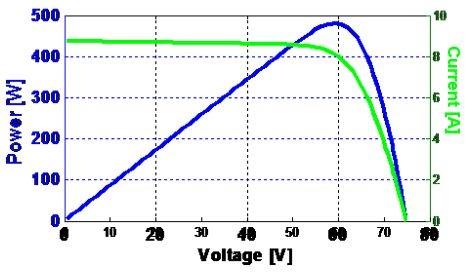
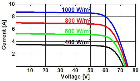
Utilizing the Eqns. (1) to (5), the solar PV generator can be modeled. In this article, the investigated solar PV generator is “Sharp ND-240QCJ Poly PV solar module” with a peek power of 240 W at a standard test condition (STC). Specifications of sharp ND-240QCJ Poly PV solar module, according to the technical requirement sheet, are summarized in Table 1. While the typical PPV-VPV and IPV-VPV characteristics of 480 W module are illustrated in Figure 4 at a constant ambient temperature of T = 25℃ and irradiance level of G =1000 W/m². Figure 5 illustrates IPV–VPV characteristic of solar PV generator under diverse irradiance levels, but at a constant ambient temperature of 25℃.
Figure 3. Solar PV generator model
Figure 4. Typical PPV-VPV and VPV-IPV characteristics curve of 480 W PV solar module at STC
Figure 5. IPV-VPV characteristic of 480 W PV solar module at T=25℃ and diverse irradiance levels
Table 1. Specifications of sharp ND-240QCJ Poly PV solar module at STC
|
Parameter |
Variable |
Value |
|
Maximum power |
PMPP |
240 W |
|
Current at the MPP |
IMPP |
8.19 A |
|
Voltage at the MPP |
VMPP |
29.3 V |
|
Open-circuit voltage |
Voc |
37.5 V |
|
Short-circuit current |
Is |
8.75 A |
|
Series resistance |
Rs |
0.409 Ω |
|
Parallel resistance |
Rp |
158.774 Ω |
|
Temp. coefficient of current |
Ki |
0.53m A/K |
|
Temp. coefficient of voltage |
Kv |
-36m V/K |
|
Number of cells per module |
Ncells |
60 cell |
2.2 DC–DC buck converter model
The DC-DC buck converter offers an output voltage that may be less than the input voltage. All components in the proposed solar PVWFS system are interconnected through two DC-DC buck converters, the first DC-DC converter is intermediated between the solar PV module and the DC source (E), in order to oblige the solar PV module to work at the MPP. Whereas, the second DC-DC converter is placed between the DC source (E) and the PMDC motor, to drive the WFS to work at the desired wire feed speed. The DC-DC buck converter used for solar PV module is composed by a solar PV panel, a self-inductance (L), a power diode (D), a power switch (S), an output capacitance (C) and a source voltage (E), as depicted in Figure 6.
Figure 6. Electrical scheme of solar PV module along with DC-DC power Converter
The DC-DC buck converter is driven by control input u(t) produced by the PWM modulator. Its principal of operation can be expressed by duty ratio (d) and switching cycle (Ts) as follows:
$u(t)=\left\{\begin{array}{ll}1, & 0 \leq t<d T_{s} \\ 0, & d T_{s} \leq t \leq T_{s}\end{array} u\left(t-T_{S}\right)=u(t) \forall t\right.$ (6)
Applying the Kirchhoff’s laws on the electrical circuit of Figure 6 distinctly in two modes of operation, ‘on’ and ‘off’, a state-space equation in a compact structure can be obtained by Eq. (7):
${{\dot{I}}_{PV}}\,=\,\frac{{{{\dot{V}}}_{PV}}}{L}d+\frac{1}{L}\left( {{V}_{PV}}-E \right)\left( 1-d \right)$ (7)
This representation is called switched form as it explains the switching behaviors of the DC-DC converters [14]. The minimum values of the self-inductance (L) and output capacitance (C) for the DC-DC power converter are precisely designed as follows:
${{L}_{\min }}\,=\,\frac{d\left( 1-d \right){{V}_{in}}}{{{f}_{s}}\Delta I}$ (8)
${{C}_{\min }}\,=\,\frac{d\left( 1-d \right){{V}_{in}}}{8\,L\,f_{s}^{2}\Delta V}$ (9)
where, Vin is the input voltage, ΔV and ΔI are the output voltage and inductance current ripples, respectively, and fs is the switching frequency of the DC-DC power converter. The parameters of both DC-DC power converters are calculated for a current ripple of 5%, a voltage ripple of 10%, a power rating of 480 W, a maximum input voltage of 200 V, an output voltage in the range of 12-48 V, and a switching frequency of 20 kHz, which can drive the Sharp ND-240QCJ Poly solar PVWFS. The parameters of the DC-DC buck converter were approximated as mentioned in Table 2.
Table 2. DC-DC buck converter design parameters
|
Parameter |
Value |
|
Self-inductor (L) |
4 mH |
|
Output capacitor (C) |
0.47 µF |
|
Switching frequency (fs) |
20 kHz |
2.3 Group wire feeder system and GMAW process model
The graphic illustration of WFS for GMAW process application is depicted in Figure 7. The wire-feed servo motor is in itself a feedback regulated system, which is able of distributing wire of wire spool to the weld process at a controlled wire-feed velocity Vf (m/s). In ordinary of cases, the value of Vf is kept constant at preferred value Vf*.
Figure 7. Physical representation of WFS for GMAW process application
The dynamic model for the electrical-circuit of GMAW process is:
${{V}_{1}}\,=\,{{L}_{1}}\frac{d{{I}_{w}}}{dt}+{{R}_{1}}{{I}_{w}}+{{V}_{arc}}$ (10)
where, V1 is the open-circuit voltage of arc welder power source, Iw is the welding current, R1 is the Thevenin resistor of arc welder power source plus cabling resistor, and L1 is the inductor of arc welder power source. The dynamic model of arc voltage Varc is given by [8]:
${{V}_{arc}}\,=\,{{k}_{a}}{{l}_{arc}}+{{k}_{p}}{{I}_{w}}+{{V}_{c}}$ (11)
where, ka, kp, Vc are coefficients of arc characteristics, and larc is the arc length. The dynamic model of arc length larc, is:
$\frac{d{{l}_{arc}}}{dt}={{V}_{m}}-{{V}_{f}}$ (12)
where, Vm characterizes the wire melting speed may be defined as follows:
${{V}_{m}}\,=\,{{k}_{m}}{{I}_{w}}$ (13)
where, km denotes the gain of wire melting speed. The dynamic model of the power supply V1 is:
${{V}_{1}}\,=\,\left( {{R}_{u}}+{{k}_{1}}{{I}_{w}} \right){{k}_{0}}$ (14)
where, Ru is the control input of the power supply, k0 is coefficient of power supply and k1 is feedback coefficient.
2.4 PMDC motor driven wire feeder system model
WFSs are available in different configurations among them the PMDC motor is the most commonly utilized type as it has high efficiency with low torque ripple [15]. PMDC motor converts electrical power provided by a solar PV generator and a DC supply voltage via a DC-DC buck converter to mechanical power provided by a spinning rotor by means of magnetic coupling. The equivalent circuit of the wire feed servo motor is illustrated in Figure 8. The armature winding of the PMDC motor can be presented by an inductor (La) in series with resistor (Ra) in series with an induced voltage (Ea) which opposes the voltage source (Va).
Figure 8. Equivalent circuit of the wire feed servo motor
According to the Kirchhoff’s voltage equation around the electrical loop, the torque equation, the back EMF equation and the motion equation of the PMDC motor of the WFS, the corresponding mathematical model of PMDC motor is as follows [7]:
${{V}_{a}}\,=\,{{R}_{a}}{{I}_{a}}+{{L}_{a}}\frac{d{{I}_{a}}}{dt}+{{k}_{a}}\omega$ (15)
${{T}_{em}}\,=\,B\omega +J\frac{d\omega }{dt}+{{T}_{L}}$ (16)
${{T}_{L}}\,=\,3.27+0.38\sin (2*\pi *{{f}_{d}}*t)$ (17)
where, Ia and Va are the phase current and voltage of the PMDC motor, Ra is the winding resistor, La is the winding inductor, J is the rotor inertia, B is the motor friction coefficient, ka is the back EMF coefficient. ω is the rotor velocity. TL and fd are the disturbance load torque and disturbance frequencies of the PMDC motor, respectively.
The parameters and their values which were utilized in simulating the PMDC motor of WFS are listed in Table 3.
Table 3. Parameters for PMDC motor of WFS
|
Parameters |
Value |
|
Armature resistance (Ra) |
1.2 Ω |
|
Armature inductance (La) |
0.96 mH |
|
Rotary inertia (J) |
1*10-7 kg.m2 |
|
Viscous damping coefficient (B) |
1.29*10-3 N.m.s/rad |
|
Back EMF coefficient (ka) |
0.057 V.s/rad |
|
Electromagnetic torque constant (k3) |
0.057 N.m/A |
|
DC input voltage (E) |
24 |
3.1 Fractional calculus
Fractional calculus is a standout amongst the basic branches of calculus in which the order of the differential and integral can be represents as a non-integer value. In FO calculus, dα/dtα can have fractional negative or positive α values. Generalized fundamental FO operator ${ }_{a} D_{t}^{\alpha}$ can be defined as below [16]:
${}_{a}D_{t}^{\alpha }\,=\,\left\{ \begin{matrix} \frac{{{d}^{\alpha }}}{d{{t}^{\alpha }}},\,\,\,\,\,\,\,\,\,\,\,\,\,\,\,\,\alpha >0\,\,\,\,\,\,\,\,\,\, \\ 1,\,\,\,\,\,\,\,\,\,\,\,\,\,\,\,\,\,\,\,\,\,\alpha =0\,\,\,\,\,\,\,\,\,\, \\ \int\limits_{\alpha }^{t}{{{(d\tau )}^{\alpha }},\,\,\,\,\,\,\,\,\,\alpha <0\,\,\,\,\,\,\,\,\,} \\\end{matrix} \right.$ (18)
where, a and t are the operation limits, whereas α is the order of integration or differentiation ($\alpha \in \mathbb{R}$). Liouville-Riemann (e.g., in FO calculus), Caputo (e.g., in physics and mathematical integration), and Letnikov-Grunwald (e.g., control and communications) definitions of FO operators are the most commonly utilized ones in an FO system [17, 18].
The situation with FO Linear-Time-Invariant (LTI) systems is dissimilar from Integer-order (IO) LTI systems, where FO systems may have roots in the right-half in the complex plane and can be still stable. Linear-Time-Invariant (LTI) FO differential equation is in the structure of the following equation:
$\begin{align} & {{a}_{n}}{{D}^{{{\alpha }_{n}}}}y(t)+\,{{a}_{n-1}}{{D}^{{{\alpha }_{n-1}}}}y(t)+\cdot \cdot \cdot +{{a}_{0}}{{D}^{{{\alpha }_{0}}}}y(t)= \\ & {{b}_{m}}{{D}^{{{\beta }_{m}}}}u(t)+{{b}_{m-1}}{{D}^{{{\beta }_{m-1}}}}u(t)++\cdot \cdot \cdot +{{b}_{0}}{{D}^{{{\beta }_{0}}}}u(t) \\\end{align}$ (19)
The system (19) can then be presented as follows:
$\sum\limits_{k=0}^{n}{{{a}_{k}}{{D}^{{{\alpha }_{k}}}}y(t)}\,=\,\sum\limits_{k=0}^{m}{{{b}_{k}}}{{D}^{{{\beta }_{k}}}}u(t)$ (20)
Applying the Laplace transformation to (19) with zero initial conditions, the continuous transfer function of the FO system can be obtained as follows:
$G(s)\,=\,\frac{{{b}_{m}}{{s}^{{{\beta }_{m}}}}+\cdot \cdot \cdot +{{b}_{1}}{{s}^{{{\beta }_{1}}}}+{{b}_{0}}{{s}^{{{\beta }_{0}}}}}{{{a}_{n}}{{s}^{{{\alpha }_{n}}}}+\cdot \cdot \cdot +{{a}_{1}}{{s}^{{{\alpha }_{1}}}}+{{a}_{0}}{{s}^{{{\alpha }_{0}}}}}$ (21)
where, αk, βk (k=0,1,2,…) are real number, αk<αk-1<…<α0, βk<βk-1<…<β0 and ak, bk (k=0,1,2,…) are arbitrary parameters.
For the implementation of FO systems in practical or simulation studies, approximations using integer-order (IO) transfer functions must be carried. The higher-order Oustaloup’s filter is one of the well-known approximation methods [19]. Who employs recursive distribution of K gain, N zeros and N poles. Hence, in this research work, the higher-order analog filter is employed for estimation of FO operators and defined by the following relations:
${{s}^{\alpha }}\,\cong {{G}_{f}}(s)=\,K\prod\limits_{k=-N}^{N}{\frac{s+\omega _{k}^{'}}{s+{{\omega }_{k}}}}$ (22)
where, $\alpha \in(0,1)$ is the order of fractional differ-integration and N is the order of approximation. The gain K, the frequencies of the zeros ωk and the poles ωk’ of the aforementioned filter are calculated from Eqns. (23) and (24) [16]:
${{\omega }_{k}}\,={{\omega }_{l}}{{\left( \frac{{{\omega }_{h}}}{{{\omega }_{l}}} \right)}^{\frac{K+N+\frac{1}{2}(1+\alpha )}{2N+1}}}\,,\omega _{k}^{'}\,={{\omega }_{l}}{{\left( \frac{{{\omega }_{h}}}{{{\omega }_{l}}} \right)}^{\frac{K+N+\frac{1}{2}(1-\alpha )}{2N+1}}}$ (23)
$K\,=\,\omega _{k}^{\alpha }$ (24)
where, ωl and ωh are the ranges of low and high frequencies [19]. For this work, frequency range is used as ω= [10-3; 103] rad/s and the 4th order Oustaloup’s recursive filter is utilized.
3.2 Fractional-order fuzzy logic PID controller
Fractional-order Fuzzy logic PID (FO-Fuzzy-PI) structure utilized in this research paper has fractional-order Fuzzy PI and Fractional-order Fuzzy PD controllers [6]. On this basis, we realized a FO-Fuzzy-PID controller for solar PVWFS system and its structure is illustrated in Figure 9. In this configuration, the derivative operator of error (DE) at the input and integral (IE) at the output are modified by their fractional counterparts [20]. Under this design, the integral action supports the elimination of the final steady-state error.
Figure 9. Fractional-order fuzzy logic PID control block diagram
In this figure Dβ is the fractional derivative and I-α is the fractional integrator orders. The values of the fractional orders {α, β}, along with the input–output scaling factors {KP, KD, KI, KU} of the FO-Fuzzy-PID regulator are the optimization variables in the PSO algorithm (presented in subsection 3.5). For the FO-Fuzzy-PID regulator presented in Figure 9, the fuzzy rule-bases can be created in the Mamdani type inference in order to investigate the nonlinearity effects of fractional operators and fuzzy mapping. The acting of all rule-bases generates the control action (U) which is a non-linear mapping function of the error (E), the fractional derivative-error (DE) and the integral-error (IE) with the following simple formula:
$U(t)=\left( f\left( {{K}_{P}}e(t)+{{K}_{D}}\frac{{{d}^{\beta }}}{dt}e(t) \right)+{{K}_{I}}\frac{{{d}^{-\alpha }}}{dt}e(t) \right){{K}_{U}}$ (25)
where, non-linear function f(.) is an input-output mapping of the fuzzy logic controller.
Figure 10 provides the non-linear decision surface of the agreed fuzzy rule-bases. Under such control surface. Table 4 presents a 7×7 rule-base employed by the FO-Fuzzy-PID regulator to be designed.
Figure 10. Rule-base for nonlinear control surface
Table 4. Rule-base of the FO-Fuzzy-PID regulator to be calibrated
|
E/DE |
NL |
NM |
NS |
ZR |
PS |
PM |
PL |
|
NL |
NL |
NL |
NL |
NL |
NM |
NS |
ZR |
|
NM |
NL |
NL |
NL |
NM |
NS |
ZR |
PS |
|
NS |
NL |
NL |
NM |
NS |
ZR |
PS |
PM |
|
ZR |
NL |
NM |
NS |
ZR |
PS |
PM |
PL |
|
PS |
NM |
NS |
ZR |
PS |
PM |
PL |
PL |
|
PM |
NS |
ZR |
PS |
PM |
PL |
PL |
PL |
|
PL |
ZR |
PS |
PM |
PL |
PL |
PL |
PL |
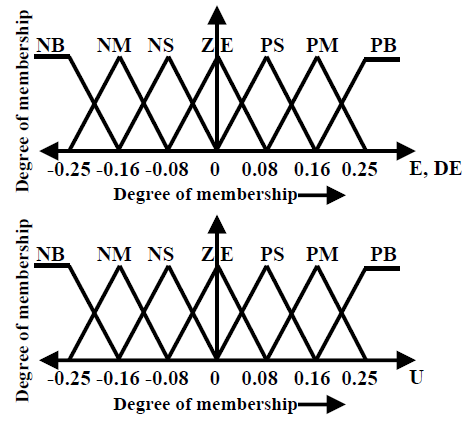
Figure 11. Membership functions for error E, fractional derivative of error DE and FLC output U
The meta-rule of the rule-base is that “IF the system error E and its derivative DE is “Large” L and moderately far from THEN the reference the control input U is “Large” L”. The triangular Membership functions (MFs) are selected for this controller. The fuzzy linguistic terms are arranged as LN, MN, SN, ZE, SP, MP, LP where L, M, S, ZE, N, P symbolize large, medium, small, zero, negative, positive, respectively. The fixed shaped MFs for the premises and consequents of the rule-base of FLC are depicted in Figure 11.
The defuzzified output of the designed FO-Fuzzy-PID controller can be calculated by the centroid of gravity method as:
${{U}_{f}}\,=\,\frac{\sum\limits_{j=1}^{47}{{{\gamma }_{j}}{{\mu }_{j}}}}{\sum\limits_{j=1}^{49}{{{\mu }_{j}}}}$ (26)
where, $\gamma_{j}$ is the vector containing the output fuzzy centers of the membership functions of output (V). $\mu_{j}$ denotes the membership value of the outputs to output fuzzy set j.
The FO-Fuzzy-PID controllers have higher performance when compared to traditional PID regulators [6]. The critical coefficient concerning the FO-Fuzzy-PID regulator is, its performance extremely depends on its scaling factors (i.e. KP, KD, KI, KU) and integral–differential orders {$\alpha, \beta$}. Without exact information concerning the solar PVWFS system, the choice of these parameters would not be perfect. Therefore, the considered FO-Fuzzy-PID regulator may not offer best performance over a wide range of working conditions. To addresses this difficulty, the present work suggests an optimal algorithm, in which FO-Fuzzy-PID controller fractional-orders are adjusted off-line along with MFs scaling factors according to the working conditions.
3.3 Particle swarm optimization (PSO) algorithm
PSO algorithm is a swarm intelligence bio-inspired population-based search process that was introduced by Kennedy for finding approximate solutions in search and optimisation problems [21]. Some utilizations of PSO algorithm are in the domain of nonlinear systems, computer science, robotics, engineering and many others in the real-world applications [6, 22]. Because the PSO algorithm is an outstanding optimization method and a promising approach for solving the optimal controller parameters problem [23]. Based on this analysis, PSO algorithm can be considered as an appropriate approach that can be utilized to search optimal FO-Fuzzy-PID controller parameters. These meta-heuristic algorithms are initialized with a random distributed population P = {p1,…, pn} of the probable candidate solutions, is commonly named ‘swarm’. The possible solutions p1, …, pn are named particles. The PSO method explores the entire space of possible solutions, where the particles ‘move’ to search for the global best-fit solution ‘Gbest’ [6]. Each individual has a velocity Vik and position Xik associated to it. The relationship to update the position and velocity of a particle ‘i’ are determined by Eqns. (27). (28), and (29), respectively.
$X_{i}^{k+1}\,=\,X_{i}^{k}+V_{i}^{k+1}$ (27)
$V_{i}^{k+1}\,=k\left[ \,wV_{i}^{k}+{{c}_{1}}{{r}_{1}}\left( {{P}_{best_{i}^{k}}}-X_{i}^{k} \right)+{{c}_{2}}{{r}_{2}}\left( {{G}_{best_{i}^{k}}}-X_{i}^{k} \right) \right]$ (28)
$k=\frac{2}{\left| 2-\phi -\sqrt{{{\phi }^{2}}-4\phi } \right|},\,\phi ={{c}_{1}}+{{c}_{2}},\,\,\phi >4$ (29)
where, c1, c2 are the acceleration-gains, Gbest is the best position of the group, Pbest is the best position of particle, r1, r2 are random real-numbers uniformly distributed between 0 and 1, k is the constriction factor, and w is the inertial weight. The performance of PSO algorithm can be increased by using a common approach to promote a balance between global and local search. In this approach, w starts with a high value and during the completing of PSO algorithm, it is decreased as shown in Eq. (30):
$w\,=\,\left( \frac{{{w}_{\max }}-{{w}_{\min }}}{ite{{r}_{\max }}} \right)\left( ite{{r}_{\max }}-iter \right)+{{w}_{\min }}$ (30)
where, wmin and wmax are the minimum and maximum values of inertial weight parameter, respectively, iter and itermax are the number of the current iteration and a maximum number of total iterations, respectively. Updated position and velocity of the swarms for one iteration in PSO algorithm are illustrated in Figure 12.
Figure 12. PSO search mechanism in multidimensional search space
3.4 The optimization problem
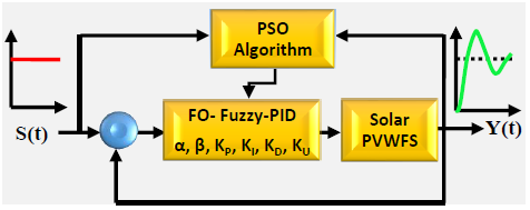
In the design stage of FO-Fuzzy-PID controller, the coefficients calibration process is transformed into a multidimensional optimization problem where fractional-orders (α and β), as well as scaling factors of the fuzzy logic controller (KP, KI, KD, KU), are both considered as decision variables. Under this strategy, the complexity of the optimization problem tends to create multi-modal error surfaces whose cost functions are significantly difficult to minimize. This work presents an algorithm for the optimal parameter calibration of FO-Fuzzy-PID controller. To calculate the gains, the optimization algorithm employs the particle swarm optimization (PSO) technique. The PSO calibration process consists of finding the optimal FO-Fuzzy-PID controllers gains that present the best possible performance for the regulation of a solar PVWFS. It executes offline search to get optimized parameters of FO-Fuzzy-PID controllers that provide better results in dynamic and steady-state. Figure 13 illustrates the PSO scheme for the parameter calibration process of a solar PVWFS.
Figure 13. Operations of the optimisation process performed by the PSO algorithm
Under such situations, the FO-Fuzzy-PID regulator gains represent the dimensions of each candidate solution for the optimization problem. To evaluate the performance of FO-Fuzzy-PID regulator under each parameter configuration (candidate solution), the Integral of Time multiply Absolute Error (ITAE) criterion has been adopted in this work based on the instantaneous error of PV module output current control loop e1(t) and instantaneous error of motor speed control loop e2(t) to get a better solution in a minimum computation time and precision. The ITAE index J measures the resemblance between the closed-loop step response Y(t) created by a determined parameter configuration and the step signal S(t). Consequently, the quality of each candidate solution is calculated according to the following objective function:
$J={{J}_{1}}+\lambda {{J}_{2}}\,=\,\int\limits_{0}^{{{t}_{sim}}}{t\left| {{e}_{1}}(t) \right|dt+}\lambda \int\limits_{0}^{{{t}_{sim}}}{t\left| {{e}_{2}}(t) \right|dt}$ (31)
where, λ is weighting factor and tsim is the time of simulation. Whereas, the problem of parameter calibration of FO-fuzzy-PID controllers for a solar PV-WFS can be formulated as a typical constrained optimization problem with twelve parameters, including: KP1, KP2, KI1, KI2, KD1, KD2, KU1, KU2, α1, α2, β1, β2:
$\begin{align} & Minimize\,\,J(x)\,\,x=\left( {{\alpha }_{1}},{{\beta }_{1}},{{K}_{P1}},{{K}_{I1}},{{K}_{D1}},{{K}_{U1}},{{\alpha }_{2}},{{\beta }_{2}},{{K}_{P2}},{{K}_{I2}},{{K}_{D2}},{{K}_{U2}} \right)\in {{\Re }^{12}} \\ & Subject\,to: 0\le {{\alpha }_{1}},{{\beta }_{1}},{{\alpha }_{2}},{{\beta }_{2}}\le 1\,;\,\,\,\,0\le {{K}_{P1}},{{K}_{P2}}\le 20;\,\,\,\,0\le {{K}_{I1}},{{K}_{I2}}\le 20; \\ & \,\,\,\,\,\,\,\,\,\,\,\,\,\,\,\,\,\,\,\,\,\,\,\,\,\,\,\,\,\,\,\,\,\,0\le {{K}_{D1}},{{K}_{D2}}\le 20;\,\,\,\,0\le {{K}_{U1}},{{K}_{U2}}\le 20 \\\end{align}$ (32)
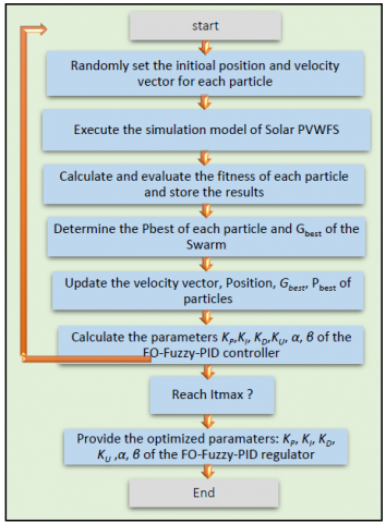
The performance of this objective function is evaluated according to PSO algorithm depicted by the flowchart of Figure 14.
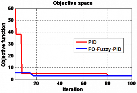
Objective function against number of iteration curve is presented in Figure 15, which shows that the considered FO-Fuzzy-PID regulator converges at a faster rate (18 iterations) compared with that for the traditional PID controller (80 iterations).
Figure 14. Schematic diagram of the PSO algorithm
Figure 15. Objective function against number of iteration curve
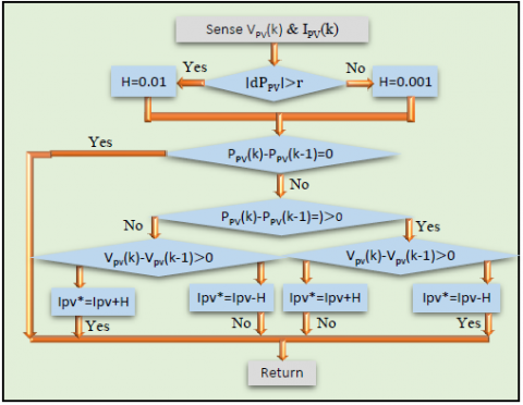
There are numerous kinds of MPPT algorithms for solar PV generators in the literature [24]. Out of all the MPPT algorithms, P&O is the most primary and prominent method. In this work, we consider an enhanced P&O algorithm with adaptive increment-step [24]. Basic principle of this strategy is increment-step variation to converge quicker towards maximal power point (MPP) while reducing oscillations around. Certainly, in order to rapidly converge, increment-step ‘H’ is reduced or adapted from a region to another: H = 0.01 in ‘F’ region and H = 0.001 in ‘G’ region (Figure 16). The diagram for the proposed P&O MPPT algorithm is explained Figure 17.
Figure 16. Basic of the improved P&O MPPT controller with an adaptive step-increment [23]
Figure 17. Diagram of the P&O MPPT controller [23]
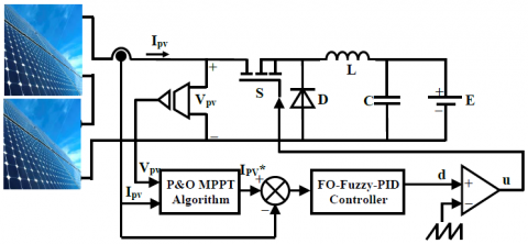
Figure 18. Control structure of FO-Fuzzy-PID current controlled P&O algorithm
Figure 18 illustrates the control structure scheme of the proposed two-stage method for P&O-based MPPT algorithm with FO-Fuzzy-PID controller, where the considered solar PV generator contains two solar PV modules of one string.
The control design composes of two loops: the first one is done based on P&O MPPT algorithm to estimate the real-time maximum power current and the second is for tracking MPP. The VPV and IPV values are measured from solar PV modules and sent to P&O MPPT searching algorithm to generate the maximum power current reference IPV*. Afterwards, the FO-Fuzzy-PID controller tracks this reference.
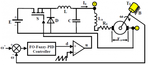
In general, the wire-feed speed regulator is calculated to achieve precise and robust optimal tracking of the desired wire-feed speed from no-load to full-load conditions. Therefore, in this article a robust FO-Fuzzy-PID controller is used to get the design objectives as closely as possible by applying an appropriate required duty ratio to the second DC-DC buck converter. Block diagram for FO-Fuzzy-PID wire feed speed control of PMDC servo motor is as given in Figure 19 below.
Figure 19. FO-Fuzzy-PID speed control of PMDC motor
Simulation results of direct coupling of solar PV modules to WFS system developed using SIMPOWER SYSTEM Toolbox of MATLAB\SIMULINK software are depicted in Figures 20-25. They verify the stability, accuracy and speed reaction of the synthesized wire-feed speed controller and intelligent MPPT algorithm.
The considered optimal FO-Fuzzy-PID regulator parameters and FO integro-differential orders are found out by the PSO algorithm and objective function J. For the optimized parameters choice problem as discussed earlier, the adopted PSO search range for the FO-Fuzzy-PID current regulator coefficients are restricted to {KP1, KI1, KD1, KV1} $\epsilon$[0; 20] and{α1, β1} $\epsilon$ [0; 1], and for the FO-Fuzzy-PID wire feed speed regulator the PSO search range {KP1, KI1, KD1, KV1} $\epsilon$ [0; 20] and{α2, β2} $\epsilon$[0; 1]. In order to perform fair an effective performance comparison the conventional PID-based P&O MPPT algorithm introduced in the study [23] is also considered in the simulation.
In addition, the tuning gains of conventional PID regulator are optimized using the PSO algorithm. The aptitude to find the MPP for the new irradiance levels is necessary. In this paper, we have investigated three test cases in order to demonstrate the tracking capability of the considered PSO-based FO-Fuzzy-PID P&O MPPT algorithm at different irradiance levels conditions. Thus, the simulation was run three times for each particular test. The first one was to display the solar PVWFS performance at constant and uniform irradiance level. The second one was to show the MPPT control performance for ramp-change in the irradiation level. Whereas, the last test was to show the solar PVWFS behavior at step-change in irradiation level.
6.1 Performance test under constant solar irradiance
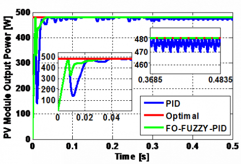
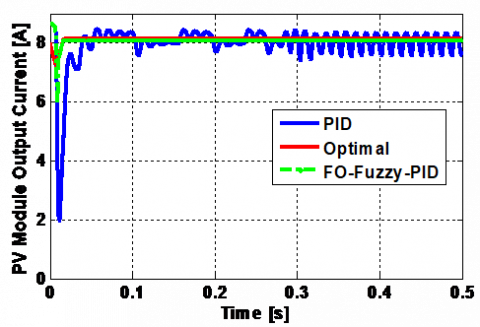
The steady-state behavior of solar PV-WFS system is illustrated in Figure 20. In this situation, the solar PV-WFS was simulated with constant and uniform irradiation on all the PV modules. A constant temperature level of 25℃ and irradiation level of 1000 W/m2 were maintained on the solar PV modules. Here the wire feed speed, and load torque of PMDC motor are maintained at their respective values of 2000 rpm and 0.07 N.m, respectively.
Figure 20. FO-Fuzzy-PID and traditional PID based MPPT control of solar PVWFS
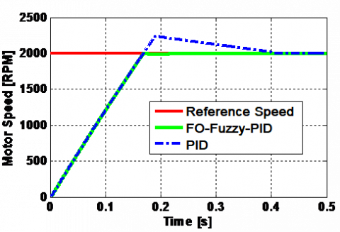
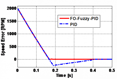
Figure 20 (top) demonstrates that P&O algorithm takes more time response to track the MPP evaluated at 40 ms. While, the proposed method achieves the MPP with quick time evaluated at 34 ms. In addition, continued oscillations are present in PV output power of of traditional method around the MPP. Furthermore, as illustrated in Figure 20 (bottom), it can be observed that the MPPT controller has the ability to track the MPP but the considered control strategy still has a rapid reaction time. Figure 21 depicts the steady-state performance of WFS including the PMDC motor speed and speed error. The results presented in these figures illustrate the rapidity and robust effective control of the response provided by the optimal FO-fuzzy-PID speed controller as well as the overshoot in the motor speed for traditional PID controller under the uniform meteorological conditions. This overshoot is compensated after a delay but leads to poorer not as good as motor speed control.
Figure 21. FO-Fuzzy-PID and traditional PID speed control and speed error of PMDC motor
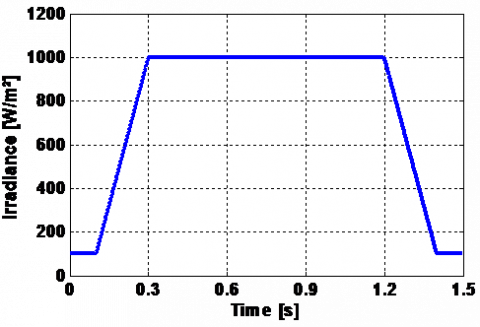
6.2 Performance test under ramp-change in solar irradiance
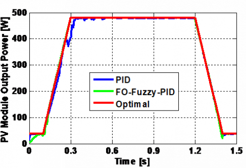
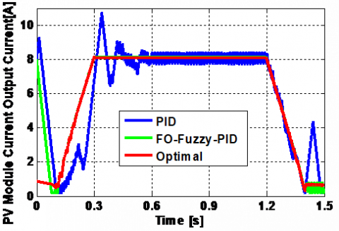
In this case, the PV modules are operated with ramp-change in solar irradiation level, such as solar irradiation level is altered linear from 100 W/m2 to 1,000 W/m2 and then 1,000 W/m2 to 100 W/m2, and corresponding simulation results are obtained for analysis. Solar irradiation in Figure 22 (top) illustrates the result for ramp-change in irradiance level test. In this case also, power of PV modules is increased linearly due to increase in irradiation level and decreased linearly with decrease in irradiance level (Figure 22 (middle)). The obtained results indicate that the proposed FO-Fuzzy-PI based-P&O MPPT algorithm can track the MPP. In fact, the extracted power is very close to the optimal power in all irradiance levels. From analysis in Figure 22, the proposed FO-Fuzzy-PID technique has better power tracking performance than other considered MPPT technique.
The speed response of the PMDC motor for this test is depicted below. The set-point of the rotor speed is changed from 2,000 rpm to 3,000 rpm as illustrated in Figure 23. It is obvious that the response of the PMDC motor speed for the proposed FO-Fuzzy-PID regulator is made significantly superior than the traditional PID regulator.
Figure 22. FO-Fuzzy-PID and traditional PID based MPPT control of solar PVWFS
Figure 23. FO-Fuzzy-PID and traditional PID speed control of PMDC motor
6.3 Performance test under step-change in solar irradiance
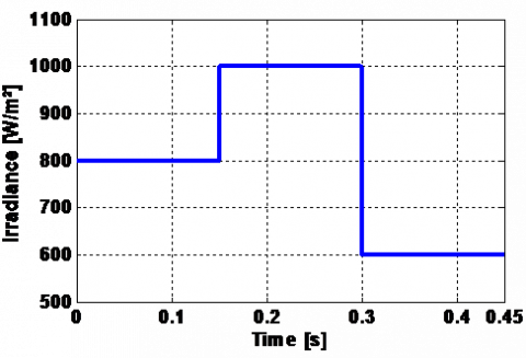
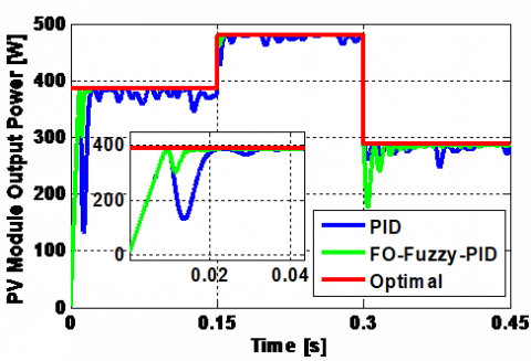
In this case, the solar PVWFS is operated with step-change in solar irradiation level in order to simulate the rapidly varying irradiation condition, such as solar irradiation level is changed arbitrarily at 0.15 s time interval and corresponding simulation results are obtained for analysis. For an extensive examination, three step-changes in solar irradiation level are implemented successively. In this test, the solar irradiation level is rapidly increased from 800 W/m2 to 1,000 W/m2, and then rapidly decreased to 600 W/m2. Figure 24 illustrates the results for step-change in solar irradiance level condition. As shown in this Figure 24 (middle), the power of solar PV modules is increased and decreased due to increase and decrease in irradiation level.
Figure 24. FO-Fuzzy-PID and traditional PID based MPPT control of solar PVWFS
Figure 24 (bottom) shows also that the proposed FO-Fuzzy-PID based MPPT strategy has the highest tracking performance than its competitor. When increasing or decreasing the irradiance level, the considered control strategy is fast to track the MPP as compared to the P&O with an efficiency of 98.95% at 800 W/m2. The MPPT tracking efficiency formula was employed, as expressed in Eq. (33):
${{\eta }_{MPPT}}\,=\,\frac{\int_{0}^{t}{{{P}_{real}}(t)dt}}{\int_{0}^{t}{{{P}_{\max }}(t)dt}}$ (33)
where, Preal and Pmax are the real and optimal power of the solar PV modules, respectively. From analysis in statistical results of Table 5, the proposed FO-Fuzzy-PID based MPPT algorithm has better tracking performance than other considered MPPT technique in terms of the tracking time (ts), the power production (Preal), the power oscillation at MPP (∆Pmax) and the efficiency of MPPT algorithm (η).
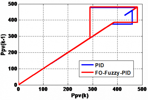
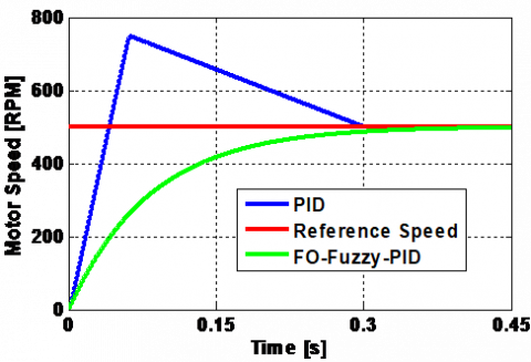
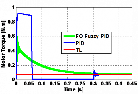
Figure 25 depicts the performance of the PMDC motor speed for the controlled WFS, and its load torque using FO-Fuzzy-PID controller at step-change in irradiance levels and constant temperature. These figures also show the resulting speed and load torque obtained with the traditional PID regulator. The comparison of their results shows that the settling-time, the overshoot and the ripples with the considered FO-Fuzzy-PID regulator are much less as compared to the traditional PID regulator.
Table 5. The performances of the two compared techniques at 800 W/m2
|
Evaluated parameters |
Considered method |
P&O based PID controller [23] |
|
Tracking speed (s) |
0.023 |
0.033 |
|
Power production (W) |
386.2 |
378 |
|
Power oscillation (W) |
1 |
26 |
|
MPPT efficiency (%) |
98.95 |
96.83 |
Figure 25. FO-Fuzzy-PID and traditional PID speed control and torque of PMDC motor
From all test cases, the proposed optimized FO-Fuzzy-PID-current controlled MPPT algorithm and optimized FO-Fuzzy-PID wire feed speed controller has superior performance in terms of smaller rise-time, settled rapidly to MPP, simply track the MPP from solar PV modules, and accurate velocity reached in the PMDC motor for all irradiance level, and it is an appropriate MPPT controller for maximum energy extraction in solar PV generator.
In this work, an advanced synthetic study of a standalone solar PVWFS is introduced. It includes: solar PV generator modeling, an improved P&O MPPT algorithm with an adaptive step-increment, a detailed method to the modeling of DC-DC buck converter, WFS and PMDC motor, and a thorough PSO algorithm for calculating the optimal coefficients of the FO-Fuzzy-PI controllers utilized for MPPT algorithm and wire feed speed control of PV module and PMDC servo motor of WFS, respectively.
This work has yielded some improvement simulation results: the response time presented by the proposed FO-Fuzzy-PID MPPT algorithm is almost less than that given by the traditional PID based P & O MPPT algorithm. The control test results confirm the FO-Fuzzy-PI speed regulator robustness and tracking effectiveness for the PMDC motor drive. The proposed FO-Fuzzy-PI control design is simple in establishment and does not demand extensive computational. The correctness of the proposed FO-Fuzzy-PI control design for solar PVWFS is guaranteed by the offline successive error driven tuning algorithm. Finally, this article with its amount of information, its references and its synthetic aspect will be helpful for researchers and PhD students, who required a simple and effective way to model, control and simulate PVWFS driven by PMDC motor.
[1] Boussiala, B., Nezli, L., Mahmoudi, M.O., Deboucha, A. (2018). Novel welding machine based on small PMSG wind turbine. Journal of Renewable and Sustainable Energy, 10: 053304. https://doi.org/10.1063/1.5042609
[2] Naidu, D.S., Ozcelik, S., Moore, K.L. (2003). Modeling Sensing and Control of Gas Metal Arc Welding. Elsevier Publications. https://doi.org/10.1016/B978-0-08-044066-8.X5000-9
[3] Greene, B.W. (1988). Arc Current Control of a Robotic Welding System: Modeling and Control System Design. B.S., University of Illinois.
[4] Jiluan, P. (2003). Arc Welding Control. Woodhead Publishing Limited and CRC Press LLC.
[5] Chaouch, S., Hasni, M., Boutaghane, A., Babes, B., Mezaache, M., Slimane, S., Djenaihi, M. (2018). DC-motor control using arduino-uno board for wire-feed system. In Proceedings of the IEEE 3rd CISTEM’18 Algiers, Algeria. https://doi.org/10.1109/CISTEM.2018.8613492
[6] Hamouda, N., Babes, B., Boutaghane, A., Kahla, S., Mezaache, M. (2020). Optimal tuning of PIλDμ controller for PMDC motor speed control using ant colony optimization algorithm for enhancing robustness of WFSs. 020 1st International Conference on Communications, Control Systems and Signal Processing (CCSSP), EL OUED, Algeria, pp. 364-369. https://doi.org/10.1109/CCSSP49278.2020.9151609
[7] Hamouda, N., Babes, B., Boutaghane, A. (2021). Design and analysis of robust nonlinear synergetic controller for a PMDC motor driven wire-feeder system (WFS). In: Bououden, S., Chadli, M., Ziani, S., Zelinka, I. (eds) Proceedings of the 4th International Conference on Electrical Engineering and Control Applications. ICEECA 2019. Lecture Notes in Electrical Engineering, vol 682. Springer, Singapore. https://doi.org/10.1007/978-981-15-6403-1_26
[8] Hamouda, N., Babes, B., Kahla, S., Boutaghane, A., Beddar, A., Aissa, O. (2020). ANFIS controller design using PSO algorithm for MPPT of solar PV system powered brushless DC motor based wire feeder unit. 2020 International Conference on Electrical Engineering (ICEE), Istanbul, Turkey, pp. 1-6. https://doi.org/10.1109/ICEE49691.2020.9249869
[9] Jegatheesh, A., Agees Kumar, C. (2020). Novel fuzzy fractional order PID controller for non linear interacting coupled spherical tank system for level process. Microprocessors and Microsystems, 72: 102948. https://doi.org/10.1016/j.micpro.2019.102948
[10] Errouhaa, M., Derouicha, A., Nahid-Mobarakeh, B., Motahhir, S., El Ghzizal, A. (2019). Improvement control of photovoltaic based water pumping system without energy storage. Solar Energy, 190: 319-328. https://doi.org/10.1016/j.solener.2019.08.024
[11] Gil, G.M.V., Rodrigues, L.L., Inomoto, R.S., Sguarezi, A.J., Monaro, R.M. (1993). Weighted-PSO applied to tune sliding mode plus PI controller applied to boost converter in a PV system. Energies, 12(5): 864. https://doi.org/10.3390/en12050864
[12] Hamouda, N., Babes, B., Kahla, S., Soufi, Y., Petzoldt, J., Ellinger, T. (2019). Predictive control of a grid connected PV system incorporating active power filter functionalities. 2019 1st International Conference on Sustainable Renewable Energy Systems and Applications (ICSRESA), Tebessa, Algeria, pp. 1-6. https://doi.org/10.1109/ICSRESA49121.2019.9182655
[13] Pradhan, R., Subudhi, B. (2016). Double integral sliding mode MPPT control of a photovoltaic system. In IEEE Transactions on Control Systems Technology, 24(1): 285-292. https://doi.org/10.1109/TCST.2015.2420674
[14] Bouafassa, A., Rahmani, L., Kessal, A., Babes, B. (2014). Unity power factor converter based on a fuzzy controller and predictive input current. ISA Transactions, 53(6): 1817-1821. https://doi.org/10.1016/j.isatra.2014.08.001
[15] El-Khatiba, M.F., Shaabana, S., Abu El-Sebah, M.I. (2017). A proposed advanced maximum power point tracking control for a photovoltaic-solar pump system. Solar Energy, 158: 321-331. http://dx.doi.org/10.1016/j.solener.2017.09.051
[16] Babes, B., Boutaghane, A., Hamouda, N., Mezaache, M. (2019). Design of a robust voltage controller for a DC-DC buck converter using fractional-order terminal sliding mode control strategy. 2019 International Conference on Advanced Electrical Engineering (ICAEE), Algiers, Algeria, pp. 1-6. https://doi.org/10.1109/ICAEE47123.2019.9014788
[17] Antar, B., Hassen, B., Babes, B., Afghoul, H. (2015). Fractional order PI controller for grid connected wind energy conversion system. 2015 4th International Conference on Electrical Engineering (ICEE), Boumerdes, pp. 1-6. https://doi.org/10.1109/INTEE.2015.7416692
[18] Miller, K.S., Ross, B. (1993). An Introduction to the Fractional Calculus and Fractional Differential Equations. Wiley Inter Science.
[19] Afghoul, H., Krim, F., Beddar, A., Babes, B. (2018). Real-time implementation of robust controller for PV emulator supplied shunt active power filter. In Proceedings of the 6th International Renewable and Sustainable Energy Conference, Rabat, Morocco. https://doi.org/10.1109/IRSEC.2018.8703010
[20] Xu, Y., Zhou, J., Xue, X., Fu, W., Zhu, W., Li, C. (2016). An adaptively fast fuzzy fractional order PID control for pumped storage hydro unit using improved gravitational search algorithm. Energy Conversion and Management, 111: 67-78. https://doi.org/10.1016/j.enconman.2015.12.049
[21] Eberhart, R., Kennedy, J. (1995). A new optimizer using particle swarm theory. Proceedings of Sixth International Symposium on Micro Machine and Human Science, pp. 39-43. https://doi.org/10.1109/MHS.1995.494215
[22] Krama, A., Zellouma, L., Benaissa, A., Rabhi, B., Bouzidi, M. (2019). Design and experimental investigation of predictive direct power control of three-phase shunt active filter with space vector modulation using anti-windup PI controller optimized by PSO. Arabian Journal for Science and Engineering, 44: 6741-6755. https://doi.org/10.1007/s13369-018-3611-6
[23] Kahla, S., Bechouat, M., Amieur, T., Sedraoui, M., Babes, B., Hamouda, N. (2020). Maximum power extraction framework using robust fractional-order feedback linearization control and GM-CPSO for PMSG-based WECS. Wind Engineering. https://doi.org/10.1177/0309524X20948263
[24] Dhaker, A., André, M., Gérar, C., Benoit, R. (2014). Real time supervision for a hybrid renewable power system emulator. Simulation Modelling Practice and Theory, 42: 53-72. http://dx.doi.org/10.1016/j.simpat.2013.12.003