Xiaopin Yang | Xinyu Liu* | Guiyue Kou | Chunxia Xu | Wenhua Zhang | Rui Hu | Cui Wang | Zhiying Zhao
© 2020 IIETA. This article is published by IIETA and is licensed under the CC BY 4.0 license (http://creativecommons.org/licenses/by/4.0/).
OPEN ACCESS
The lubrication needs of wind turbines vary with the operating conditions. To provide a dynamic lubrication scheme for wind turbines under variable conditions, this paper designs a dynamically adjustable lubrication scheme through parallel control of multiple influencing factors. Based on mid- and long-term loads, the proposed scheme fully considers the influence of various sudden changes in addition to slowly changing factors like load, operating hours, and speed, such as to dynamically adjust the injection flow as per the specific operating condition of the turbine. The ideal lubrication effect was tracked through the adjustment of the injection flow or injection time, and used to determine the optimal dynamic lubrication control strategy during turbine operation. The proposed control strategy overcomes the defects of the traditional fixed-time fixed-flow lubrication approach, and provides reasonable on-demand lubrication schemes for wind turbines in different operating conditions. The on-demand injection of lubricant prevents under- or over-lubrication, reduces the rate of mechanical failure, and extends the service life of wind turbines. Suffice it to say that the proposed control strategy can lower power generation cost and save energy, making wind turbines more profitable.
wind turbine, dynamic lubrication, control strategy, multiple factors, parallel control
Wind farms are generally built in harsh environments like deserts, valleys, high mountains, or seas. It is no easy task to maintain the wind turbines. The difficulty of maintenance, coupled with the high cost of wind turbines, highlights the importance of lubrication to the continuous normal operation of wind turbines [1]. Apart from ensuring the safe and stable turbine operations, good lubrication can save lubricant and reduce the electricity cost. The lubrication of a wind turbine should focus on an important mechanical part: the bearing. The wind turbine cannot operate normally, if its bearing is not sufficiently lubricated [2-4].
Currently, wind turbines are lubricated either manually or automatically [5]. In terms of automatic lubrication, the lubricant is injected automatically by the master control system of the wind turbine. This strategy faces multiple defects: the lubrication program occupies the precious resources of the master control program, the feedback signals encroach on the input/output (I/O) points of the master control system, and the manual adjustment of the master control program is sometimes needed to change the lubrication parameters.
Lubrication mainly involves fixed-time fixed-value parameters like lubrication interval and injection flow. The basically manual adjustment of these parameters cannot fully satisfy the lubrication needs. The intelligent functions of the automatic lubrication scheme stop at timing, parameter setting, grouping, and multi-point lubrication. The lubrication scheme cannot be adjusted automatically.
Wind energy is a stochastic and unstable power. During the operation of the wind turbine, the lubrication needs of the bearing depend heavily on load intensity, operating time, environment, and temperature [6, 7]. The current schemes of manual or automatic lubrication only support fixed-flow lubrication at fixed time, failing to provide the lubrication flow according to the actual operating condition of the wind turbine. The equipment will be overlubricated if the time is too short or the flow is too high, and under-lubricated if the time is too long or the flow is too low. In either case, the service life of the wind turbine will be greatly shortened.
Despite its importance, dynamic lubrication has not been extensively studied. Besides, wind power generation is a relatively new concept. The intelligent lubrication of wind turbines has not attracted sufficient attention. In the long run, it is of great significance to develop an adjustable dynamic lubrication scheme, which facilitates the design of maintenance-free wind turbines.
Through the above analysis, this paper proposes a dynamic lubrication control strategy for wind turbines based on the parallel control of multiple influencing factors [8-10]. The lubrication needs under specific operating conditions were determined, in the light of multiple factors, namely, turbine output and relevant environmental impacts. According to the operating condition and lubrication state, adjustable dynamic lubrication was applied to the wind turbine. Under the proposed strategy, it is possible to prepare a reasonable lubrication scheme for the wind turbine, without inducing over- or under-lubrication.
The remainder of this paper is organized as follows: Section 2 analyzes and models the main factors affecting the lubrication of wind turbines [11-14]; Section 3 introduces the principle of parallel control of multiple factors, formulates a preliminary lubrication scheme based on the predicted wind power, and adjusts the scheme in real time according to the error between the predicted data and actual data, as well as the sudden change of operating conditions; Section 4 proves the feasibility of the proposed control strategy through bearing wear experiments, and comparative simulations on wind turbine lubrication; Section 5 puts forward the conclusions.
To prepare a suitable lubrication scheme, it is critical to analyze the factors that greatly affect lubrication, and control their influence effectively during the lubrication [15, 16]. Therefore, this paper probes deep into the impact of internal and external factors on lubrication performance, providing theoretical and practical supports to the design of dynamic lubrication control strategy.
2.1 Geographical location
Wind turbines are often scattered across the wind farm. The large spatial differences between them lead to varied operating conditions. Due to the influence of terrain and aerodynamics, the output of a wind turbine hinges on its position and windward point, and the wind turbines in the same wind farm differ in operating conditions. Those in the prevailing wind direction have greater output than those in the other directions.
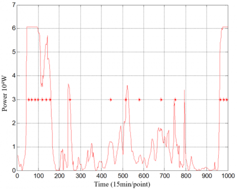
Figure 1 shows the wind power data of four wind turbines collected at the same time in a wind farm to the north of the Poyang Lake. Obviously, even if they belong to the same wind farm, the wind turbines had a sharp difference in the wind power at the same time. Since the wind energy is converted into electrical energy through the main drive chain, the difference in wind power also reflects the huge discrepancy in operating conditions of the wind turbines.
Figure 1. The wind power data of four wind turbines in a wind farm
2.2 Temperature influence
The operating temperature of the bearing is related to many factors. The primary factors include load, speed, operating environment, and type of lubricant. Temperature has a great influence on the lubricant performance, which in turn determines the lubrication effect. The formation of lubricant film on the bearing relies on the viscosity of the lubricant, which is highly sensitive to temperature variation. Therefore, temperature exerts a noneligible impact on the lubrication effect.
The entire wind turbine is exposed to the outdoor environment. In extreme weather in summer and winter, the interior temperature of the turbine has a large gradient, creating a harsh working environment for the bearing.
The temperature variation can be detected by various methods. Theoretically, the temperature change can be estimated by the equation set proposed by T.A. Harris: First, a temperature node system is set up for the bearing and its seating; Then, the equation set is solved by Newton-Raphson method; If the mean squared error is sufficiently small, the current value is taken as the original temperature; After that, the temperature after the variation is solved, and substituted into the viscosity-pressure-temperature equation to derive the viscosity of the lubricant; Finally, the temperature impact on viscosity is quantified.
2.3 Pollution coefficient
Among lubrication pollutions, particle pollution could bring serious consequences. In severe cases, the bearing will fail rapidly. Particle pollution can be divided into the invasion of external particles and the spalling of internal particles. The particle invasion dampens the lubrication effect, and reduces the service life of the bearing. According to the specific size of pollutant particles, the pollution coefficient was designed to quantify the influence of each impurity on the fatigue life of the bearing:
$e_{c}=x_{2} k^{0.68} D_{p w}^{0.55}\left(1-\frac{x_{1}}{D_{p w}^{1 / 3}}\right)$ (1)
Formula (1) can be simplified into:
$e_{c}=\left(3.387-\frac{b_{1}(k)}{k^{b_{2}(k)}}\right)^{5 / 2}$ (2)
where, k is the viscosity ratio; b1 and b2 are parameters related to the bearing model.
2.4 Load
Load is a key external factor that affects friction and wear. The amount of wear and the friction coefficient vary significantly with load. The thickness of lubricant film between contact surfaces also change with load. If the load changes suddenly, the morphology of the lubricant film will inevitably change.
Dynamic pressure effect and squeeze effect are the leading sources of pressure on the lubricant film. Figure 2 presents the pressure distribution on the lubricant film under different squeeze effects.
Only with a proper thickness, can the lubricant film separate two contact surfaces and maintain good lubrication. After the load suddenly doubled, the pressure on the lubricant film changed drastically, indicating that sudden load change is an external factor that affects the lubrication effect.
Under unstable load and speed, the mean equivalent dynamic load P can be derived from the load sequence. When the load P and speed n continues to change, the equivalent dynamic load and speed of the bearing are denoted as P1, P2, P3...Pk and n1, n2, n3...nk, respectively, and the time fraction of each load level is denoted as a1, a2, a3...ak. Then, the mean equivalent speed and mean equivalent dynamic load of the bearing can be respectively expressed as:
$n_{m}=n_{1} a_{1}+n_{2} a_{2}+n_{3} a_{3}+\ldots+n_{k} a_{k}$ (3)
$P_{m}=\sqrt[\tau]{\frac{n_{1} a_{1} P_{1}^{\tau}+n_{2} a_{2} P_{2}^{\tau}+n_{3} a_{3} P_{3}^{\tau}+\ldots+n_{k} a_{k} P_{k}^{\tau}}{n_{m}}}$ (4)
where, τ is an index (τ=3 for ball bearing; τ=10/3 for roller bearing).
Figure 2. The pressure distribution on the lubricant film under different squeeze effects
2.5 Viscosity ratio
The effectiveness of the lubricant mainly depends on the degree of separation between the rolling contact surfaces. To form a film with sufficient lubrication and separation effect, the lubricant must maintain a minimum viscosity when it reaches the working temperature.
The condition for the lubricant to separate the surfaces can be characterized by viscosity ratio k: the ratio of actual kinematic viscosity v to the reference kinematic viscosity v1. Taking the mean diameter 0.5 (d+D) as the diameter of the pitch circle DPW, the reference kinematic viscosity can be computed by:
$v_{1}=45000 n^{-0.83} D_{p w}^{-0.5}(n<1000 r / \min )$
$v_{1}=4500 n^{-0.83} D_{p w}^{-0.5}(n \geq 1000 r / \min )$ (5)
The influence of lubrication state on service life k=Λ1.3 can be deduced from the film thickness ratio Λ:
$\Lambda=\frac{h_{\min }}{\sqrt{\sigma_{1}^{2}+\sigma_{2}^{2}}}$ (6)
A reasonable dynamic lubrication scheme was prepared by tracking and adjusting the rational lubrication state under many disturbance conditions. Firstly, historical data of the wind turbine were analyzed to determine the operating features. Then, the operating intensity and mechanical performance of the turbine were evaluated comprehensively under the predicted conditions, and used to formulate the preliminary lubrication scheme. From the various influencing factors of the control strategy (e.g. weather condition, turbine location, turbine dimension, operating intensity, lubricant requirements, lubricant degradation, and previous lubrication effect) [17-19], the factors with relatively high influence were selected for adjustment. Finally, the final control strategy was prepared and implemented according to the actual operating data. Taking the main bearing in the active drive chain for instance, the preparation of the lubrication scheme is detailed as follows.
3.1 Modification of bearing service life
As mentioned in Rolling Bearings: Dynamic Load Ratings and Rating Life (GB/T6391-2010; ISO281:2007), the service life of the bearing can be calculated by:
$L_{\mathrm{nm}}=\mathrm{a}_{1} a_{\mathrm{ISO}} L_{10}$ (7)
where, Lnm is the modified service life; L10 is the rating service life; a1 is the modification coefficient for reliability; aISO is the modification coefficient for service life. Among them, aISO is the only variable coefficient:
$a_{\mathrm{ISO}}=f\left(\frac{e_{C} C u}{P}, \kappa\right)$ (8)
Formula (8) is a complex function related to pollution coefficient eC, fatigue load limit Cu, equivalent dynamic load P, and viscosity ratio k. By this formula, L10 can be modified under the combined effects of the factors in the dynamic operation of the bearing, namely, the fatigue limit of bearing material, the effectiveness of lubrication, the degree of pollution, and the equivalent dynamic load. To extend the service life of the bearing, it is possible to increase the modified service life Lnm to the expected length by adjusting the aISO value.
Considering the overall influence of the fatigue limit of bearing material, the effectiveness of lubrication, the degree of pollution, and the equivalent dynamic load over the fatigue life of the bearing, the calculation formula of aISO was derived from Rolling Bearings: Dynamic Load Ratings and Rating Life (GB/T6391-2010; ISO281:2007):
$a_{\mathrm{ISO}}=0.1\left(1-\left(x_{1}-\frac{x_{2}}{k^{e 1}}\right)^{e 2}\left(e_{c} \frac{C u}{P}\right)^{e 3}\right)^{e 4}$ (9)
3.2 Multi-factor parallel control strategy
Before lubrication, a preliminary scheme had been formulated through the analysis on historical and predictive data [20, 21]. However, many influencing factors might change during the turbine operation, such as operating temperature, turbine start/stop, as well as sudden changes of speed and load. These changes will undermine the effect of the preliminary lubrication scheme. This calls for the design of a new lubrication scheme without hindering the application of lubricant. Besides, the new scheme should minimize the disturbance on objective functions like lubrication effect. As a result, it is of practical significance to dynamically optimize the lubrication effect of the preliminary scheme in real time in the presence of interference events, while minimizing the influence of various factors on the lubrication effect.
Let aISO0 be the ideal modification coefficient aISO0. The preliminary scheme was first prepared according to the predicted data. When the injection flow is fixed, the injection interval, equivalent load, and viscosity under ideal condition are denoted as t, P, and k, respectively. Then, the ideal modification coefficient for service life can be defined as:
$a_{\mathrm{ISO} 0}=0.1\left(1-\left(x_{1}-\frac{x_{2}}{k_{0}^{e 1}}\right)^{e 2}\left(e_{c 0} \frac{C u}{P_{0}}\right)^{e 3}\right)^{e 4}$ (10)
Suppose the injection time is ti under the predicted situation. During the injection interval, the equivalent load, viscosity, and pollution coefficient are denoted as Pi, ki, and eci, respectively. Then, we have:
$a_{\mathrm{ISOi}}=0.1\left(1-\left(x_{1}-\frac{x_{2}}{k_{i}^{e 1}}\right)^{e 2}\left(e_{c i} \frac{C u}{P_{i}}\right)^{e 3}\right)^{e 4}$ (11)
If ∀ is a column of original data $\exists t_{i}$ that makes fi→0, then the sequence {ti} of time points corresponding to fi is the preliminary time interval of lubrication injection:
$f_{i}=\min \left\{f\left(\frac{e_{C 0} C u}{P_{0}}, \kappa_{0}\right)-f\left(\frac{e_{C i} C u}{P_{i}}, \kappa_{i}\right)\right\}$ (12)
The preliminary scheme mainly considers the influence of mid- and long-term slow-changing dynamic factors like load, temperature, and speed. For radial roller bearings, the modification coefficient can be defined as:
$a_{\mathrm{ISO}}=\left\{\begin{array}{c}0.1\left(1-\left(1.5859-\frac{1.3993}{k^{0.054381}}\right)\left(e_{c} \frac{C u}{P}\right)^{0.4}\right)^{-9.185} \quad(0.1 \leq k<0.4) \\ 0.1\left(1-\left(1.5859-\frac{1.2348}{k^{0.19087}}\right)\left(e_{c} \frac{C u}{P}\right)^{0.4}\right)^{-9.185}\quad(0.4 \leq k<1) \\ 0.1\left(1-\left(1.5859-\frac{1.2348}{k^{0.71739}}\right)\left(e_{c} \frac{C u}{P}\right)^{0.4}\right)^{-9.185} \quad(1\leq k<4)\end{array}\right.$ (13)
During the operation of the wind turbine, there are often various perturbations of external factors, such as sudden changes in operating conditions and external environment. Under these perturbations, the lubrication effect of the preliminary scheme will be affected. Then, it is necessary to prepare a new lubrication scheme by adjusting the lubrication parameters. The new scheme should ensure the lubrication effect, while minimizing the influence of interference events. In other words, the new scheme should realize real-time dynamic lubrication, and achieve the optimal lubrication effect:
$f_{i}=\min \left\{f\left(\frac{e_{C 0} C u}{P_{0}}, \kappa_{0}\right)-f\left(\frac{e_{C i} C u}{P_{j}}, \kappa_{i}\right) f\left(t, P^{\prime}, H\right)\right\}$ (14)
Treating various influencing factors as perturbations, the parallel control strategy modifies the lubrication scheme throughout the lubrication process, according to the interference situation. Comparing the field data with the predicted data, the modified scheme attaches importance to sudden factors like sudden load change, rapid temperature rise, and manual finetuning, in addition to slowly changing factors.
4.1 Simulation
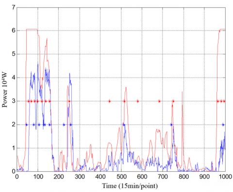
Figure 3. The comparison between predicted wind speed and measured wind speed
Figure 4. The comparison between predicted power and the power of the preliminary scheme
Based on the data from a wind farm in southeastern China’s Jiangxi province, the authors prepared a fixed-time variable-flow lubrication strategy and a variable-time fixed-flow lubrication strategy. The simulation results of the two strategies are displayed in Figures 3-8.
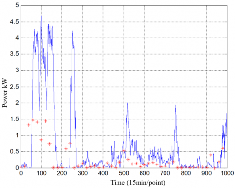
Figure 5. The comparison between measured power and the power of the modified scheme
Figure 6. The comparison between the preliminary scheme and the modified scheme
Considering the features of the lubricant injection device, the authors prepared a time adjustable lubrication scheme, and a flow adjustable lubrication scheme. Both suddenly changing factors and slowly changing factors were fully considered during scheme preparation. As can be seen from data analysis and simulation figures, the slowly changing factors had a limited impact on the modified scheme, due to their small changes; suddenly changing factors had a significant impact on the scheme. The suddenly changing factors are turbine start/stop, and sudden load change, both of which are present in scheme implementation. From offline testing of lubricant, the particle pollution was rather insignificant. This explains the basically stable trend of the pollution coefficient.
4.2 Physical experiments
The feasibility of the dynamic lubrication scheme was verified through a series of wear experiments in the lab. The wear experiments are destructive. It is difficult to test the whole machine, owing to the high cost of high-power wind turbine. Therefore, the bearing of the active drive chain was selected as the target of physical experiments [22]. Without changing its failure mechanism, the bearing was subjected to intensified experiments. The actual load on the turbine shaft was scaled, and compiled into a load spectrum, which was applied on the bearing during the wear experiments. The lubrication method was also determined based on the load spectrum.
Figure 7. The preliminary scheme of fixed-time variable-flow lubrication strategy
Figure 8. The modified scheme of fixed-time variable-flow lubrication strategy
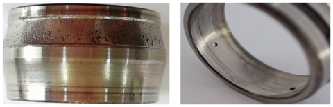
Figure 9. The morphology of the inner and outer rings
Figure 10. The morphology of the roller
Figure 11. The roughness of the inner ring
According to the abovementioned method, different lubrication schemes were formulated for load-temperature rise, lubrication-wear experiments. Each group of experiments lasted 190h on a BLT-M2C testing machine. After the experiments, the bearing was disassembled and inspected. The morphology and main results of the typical sample under each condition are presented below.
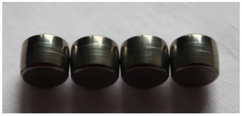
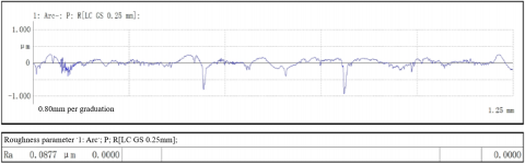
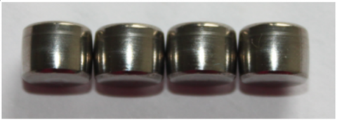
(1) Figures 9, 10, and 11 show the morphology of the inner and outer rings, the morphology of the roller, and the roughness of the inner ring of the bearing without being treated with the dynamic lubrication scheme, respectively. It can be seen that the surface of the inner ring was fatigued, the roller surface was seriously damaged, and the bearing was in the failure state.
(2) Figures 12, 13, and 14 show the morphology of the inner and outer rings, the morphology of the roller, and the roughness of the inner ring of the bearing under the control of slowly changing factors. Judging by the morphology and roughness, the bearing maintained good mechanical performance.
(3) Figures 15 and 16 show the morphology of the inner and outer rings, and the morphology of the roller of the bearing without controlling the suddenly changing factors (e.g. sudden temperature rise, and sudden load change). It can be seen that the inner and outer ring surfaces were discolored and burned to varied degrees, owing to sudden temperature rise, sudden load change, and insufficient lubrication. Burns can reduce the hardness or induce microcracks on parts surface, posing a serious threat to the mechanical properties of the bearing.
Figure 12. The morphology of the inner and outer rings
Figure 13. The morphology of the roller
Figure 14. The roughness of the inner ring
Figure 15. The morphology of the inner and outer rings
Figure 16. The morphology of the roller
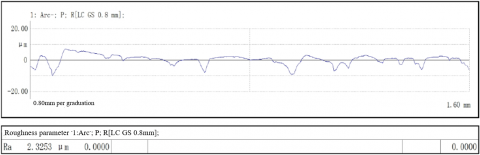
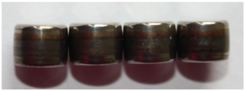
(4) Figures 17, 18, and 19 show the morphology of the inner and outer rings, the morphology of the roller, and the roughness of the inner ring of the bearing through the parallel control of multiple factors, including suddenly changing factors. The morphology and roughness demonstrate the good mechanical properties of the bearing.
Figure 17. The morphology of the inner and outer rings
Figure 18. The morphology of the roller
Figure 19. The roughness of the inner ring
Through surface roughness comparison, it can be inferred that the contact surfaces were much less worn under the dynamic lubrication scheme than under the fixed-time fixed-flow scheme. This means the dynamic lubrication scheme is more effective than the traditional approach in bearing protection, and lubrication. Under dynamic lubrication control, the lubrication effect is fully displayed to safeguard the normal operation, extend the service life, and reduce the fault and stop rates of wind turbines, thereby lowering the cost and resource consumption of wind power generation.
Dynamic lubrication of wind turbine aims to continuously adjust the lubrication scheme according to the actual operating state of the turbine. However, many random factors exist in the lubrication process, namely, temperature rise, sudden change of operating condition, and the lack of lubricant. These factors severely limit the effectiveness of the lubrication scheme. To solve the problem, this paper proposes a multi-factor parallel control strategy to realize dynamic lubrication of wind turbine. Under the strategy, an ideal lubrication scheme is formulated based on the predicted data. Taking the various influencing factors as random disturbances, the actual and ideal operating conditions were analyzed, and the preliminary scheme was modified to improve the lubrication effect. Simulation and experimental results demonstrate the effectiveness of the proposed strategy. The future research will carry out large sample experiments on the proposed strategy, and investigate the cross influence between even more factors.
This paper is supported by National Natural Science Foundation of China (Grant No.: 51567018, 51667015, 51765044, 21603093), Natural Science Foundation of Jiangxi Province (Grant No.: 20202BABL204050) and Science and Technology Project Founded by the Education Department of Jiangxi Province in China (Grant No.: GJJ180934, GJJ180960).
[1] Yang, X.P., Sun, Y.F., Song, C.H., Zhang, S.H. (2014). The distributed intelligent lubricating system for wind turbines. In Advanced Materials Research, 1008: 169-172. https://doi.org/10.4028/www.scientific.net/AMR.1008-1009.169
[2] Hu, R., Xu, C. (2017). Influence of magnetic fluids’ cohesion force and squeeze dynamic effect on the lubrication performance of journal bearing. Advances in Mechanical Engineering, 9(9): 1687814017732671. https://doi.org/10.1177/1687814017732671
[3] Hu, R., Hewson, R., Morina, A., Liu, Z. (2014). Influence of material properties and operating conditions on the predicted performance of poroelastic faced bearings. Proceedings of the Institution of Mechanical Engineers, Part J: Journal of Engineering Tribology, 228(2): 131-139. https://doi.org/10.1177/1350650113511598
[4] Dai, Y., Wu, W., Zhou, H.B., Zhang, J., Ma, F.Y. (2018). Numerical simulation and optimization of oil jet lubrication for rotorcraft meshing gears. International Journal of Simulation Modelling, 17(2): 318-326. https://doi.org/10.2507/IJSIMM17(2)CO6
[5] Li, L., Zhang, D., Xie, Y. (2019). Effect of misalignment on the dynamic characteristic of MEMS gas bearing considering rarefaction effect. Tribology International, 139: 22-35. https://doi.org/10.1016/j.triboint.2019.06.015
[6] Jang, J.Y., Khonsari, M.M. (2019). Performance and characterization of dynamically-loaded engine bearings with provision for misalignment. Tribology International, 130: 387-399. https://doi.org/10.1016/j.triboint.2018.10.003
[7] Xiang, G., Han, Y., Wang, J., Xiao, K., Li, J. (2019). A transient hydrodynamic lubrication comparative analysis for misaligned micro-grooved bearing considering axial reciprocating movement of shaft. Tribology International, 132: 11-23. https://doi.org/10.1016/j.triboint.2018.12.004
[8] Yang, X.P., Gao, X.L. (2018). Optimization of dynamic and multi-objective flexible job-shop scheduling based on parallel hybrid algorithm. International Journal of Simulation Modelling, 17(4): 724-733. https://doi.org/10.2507/IJSIMM17(4)CO19
[9] Yang, X.P., Gao, Y.L. (2019). Production scheduling problem based multifactor dynamic analysis algorithm. Academin Journal of Manufacturing Engineering, 17: 146-152.
[10] Zhang, H.P., Ye, J.H., Yang, X.P., Muruve, N.W., Wang, J.T. (2018). Modified binary particle swarm optimization algorithm in lot-splitting scheduling involving multiple techniques. International Journal of Simulation Modelling, 17(3): 534-542. https://doi.org/10.2507/IJSIMM17(3)CO13
[11] Li, Z.P., Zhang, J.L., Zhang, H.J., Hua, G.W. (2017). Optimal selection of movable shelves under cargo-to-person picking mode. International Journal of Simulation Modelling, 16(1): 145-156. https://doi.org/10.2507/IJSIMM16(1)CO2
[12] Yu, H. (2018). Numerical simulation of European option payoff based on stochastic differential delay equations. Mathematical Modelling of Engineering Problems, 5(2): 102-107. https://doi.org/10.18280/mmep.050207
[13] Burdett, R.L., Kozan, E. (2015). Techniques to effectively buffer schedules in the face of uncertainties. Computers & Industrial Engineering, 87: 16-29. https://doi.org/10.1016/j.cie.2015.04.024
[14] Gürel, S., Cincioğlu, D. (2015). Rescheduling with controllable processing times for number of disrupted jobs and manufacturing cost objectives. International Journal of Production Research, 53(9): 2751-2770. https://doi.org/10.1080/00207543.2014.980452
[15] Xu, M., Dai, Q., Huang, W., Wang, X. (2020). Using magnetic fluids to improve the behavior of ball bearings under starved lubrication. Tribology International, 141, 105950. https://doi.org/10.1016/j.triboint.2019.105950
[16] Toumi, M.Y., Murer, S., Bogard, F., Bolaers, F. (2018). Numerical simulation and experimental comparison of flaw evolution on a bearing raceway: Case of thrust ball bearing. Journal of Computational Design and Engineering, 5(4): 427-434. https://doi.org/10.1016/j.jcde.2018.01.004
[17] Olaru, D.N., Bălan, M.R.D., Tufescu, A., Cârlescu, V., Prisacaru, G. (2017). Influence of the cage on the friction torque in low loaded thrust ball bearings operating in lubricated conditions. Tribology International, 107: 294-305. https://doi.org/10.1016/j.triboint.2016.11.042
[18] Qiu, M., Yang, Z., Lu, J., Li, Y., Zhou, D. (2017). Influence of step load on tribological properties of self-lubricating radial spherical plain bearings with PTFE fabric liner. Tribology International, 113: 344-353. https://doi.org/10.1016/j.triboint.2017.02.047
[19] Hu, Z., Wang, Z., Huang, W., Wang, X. (2019). Supporting and friction properties of magnetic fluids bearings. Tribology International, 130: 334-338. https://doi.org/10.1016/j.triboint.2018.10.006
[20] Zheng, L., Zhu, H., Zhu, J., Deng, Y. (2020). Effects of oil film thickness and viscosity on the performance of misaligned journal bearings with couple stress lubricants. Tribology International, 146: 106229. https://doi.org/10.1016/j.triboint.2020.106229
[21] Han, B., Huang, Z., Le, Y. (2017). Design aspects of a large scale turbomolecular pump with active magnetic bearings. Vacuum, 142: 96-105. https://doi.org/10.1016/j.vacuum.2016.12.010
[22] Fekry, M., Mohamed, A.M., Fanni, M., Yoshida, S. (2019). A Comprehensive performance assessment of the integration of magnetic bearings with horizontal axis wind turbine. Mathematics and Computers in Simulation, 156: 1-39. https://doi.org/10.1016/j.matcom.2018.06.011