Ibrahim Chouidira* | Djalal Eddine Khodja | Salim Chakroune
© 2020 IIETA. This article is published by IIETA and is licensed under the CC BY 4.0 license (http://creativecommons.org/licenses/by/4.0/).
OPEN ACCESS
This study aims to display fuzzy logic (FL) technique for diagnosis of fault induction machine. This allows monitoring of fuzzy information from different signals to give more accurate judgment on the health of the engine, through using a multi-winding model of induction machine for the simulation of broken bars. This model allows study the influence of defects and appear the behavior of the machine in the different modes of running conditions (healthy and fault). In this work, we focus the application of a fuzzy logic technique based on the fast Fourier transformation (FFT) by analyzing the stator current for fault detection. The results of the simulation obtained allowed us to show the importance of the fuzzy logic approach based on classification of signals for detecting the faulty.
induction machine, detection, diagnosis, fuzzy logic, fast fourier transformation
Machine monitoring has become a very important operation in the field of maintenance and control of electrical devices. The performance and reliability of all control are linked to the quality of the measurement systems. Any failure of the instrumentation leads to the generation of erroneous information, and therefore a reduction in performance and reliability and sometimes even a security issue [1].
Induction machines play a big role in the industrial and commercial frame because of its important role in the production and its growing demand, due to the many advantages, namely: simplicity of construction, robustness, relatively low manufacturing cost. Consequently, modern industrial machines rely more and more on advanced diagnostic techniques to reach high-performance levels and meet the requirements of industrial companies. The continuous diagnostic function of the equipment through knowing about faults early can prevent a malfunction before it happens and rule out improbable expectations that can slow down machine work [2, 3]. The diagnosis of the machine state is only possible if knowing the vibratory symptoms associated with each fault. Also, consider the faults reasons in electrical machines: their origin in the design, the installation, the operating environment, the nature of the load and the maintenance program where the faults are classified according to their location and the reasons for their presence [4]. However, the failures at the bar of the rotor can damage the surrounding bar and thus, damage can spread leading to several fractures of the bar. When a bus bar fault occurs, flow harmonics are produced according to the next relation: $f_{b r c}=f_{\mathrm{s}}(1 \pm 2 \mathrm{ks})$ [5]. Recently, it led to the interest of researchers at the importance of detection broken bar fault and its maintenance. In this context, it has suggested a novel methodology for rotor broken bar (BRB) detection in IM during both start-up and a steady-state operation regime is proposed. It consists of two main steps. In the first one, the analysis of 3-axes vibration signals using the fractal dimension (FD) theory is carried out. In the second step, a fuzzy logic system for each regime is presented for automatic diagnosis [6]. Whereas Karnavas et al. [7] presented an attempt is made to develop a mechanism to diagnose rotor bars faults in squirrel cage induction machine. The concept is implemented by primarily taking into account the information extracted from the classical, through motor current signature analysis (MSCA) for broken three bars and then a model identification method approach is formulated using data set manipulation known as subtractive clustering. The method is based on adaptive neuro-fuzzy inference system (ANFIS). While Merabet et al. [8], which proposes a reliable method for diagnosis and detection of rotor broken bars faults in induction machine. The detection faults are based on the monitoring of the current signal. Also the calculation of the value of relative energy for each level of signal decomposition using package wavelet, which will be useful as data input of adaptive Neuro-Fuzzy inference system. In this method, fuzzy logic is used to make decisions about the machine state. The adaptive Neuro-Fuzzy inference system can identify the IM bearing state with high precision. Whilst Prins et al. [9] present an online fault detection technique based on multilevel discrete wavelet transform DWT followed by the statistical analysis of the coefficients using correlation coefficient to detect the presence of a broken bar in the rotor of a three-phase induction motor.
To solve these issues, this paper establishes a model based on a multi-winding to simulate broken bars, to study the influence of these faults in the behavior of the machine. Where the fuzzy logic provides an insight into the condition of the machine (in case of healthy and fault) and is used as the advantage to extract the details of the indicators when the fault occurs.
This paper has been divided into three parts. The first part deals with introduces model multi-winding to simulate a broken bar, the second describes the way of fuzzy logic working, depending on FFT values. Finally, we present the results of fuzzy logic and evaluation of induction machine behavior for detecting the faults.
The application of extended Park transformation of rotor system to transform the system in Nr phases in a system (d, q). The mathematical model of the squirrel cage induction motor can be written as:
$[\mathrm{L}] \frac{\mathrm{dI}}{\mathrm{dt}}=[\mathrm{V}]-[\mathrm{R}][\mathrm{I}]$ (1)
While the principal inductance of the magnetizing stator phase is:
$\mathrm{L}_{\mathrm{sp}}(\theta)=\frac{\phi_{\mathrm{sp}}}{\mathrm{i}_{\mathrm{a}}}=\frac{2 \mu_{0} \mathrm{N}_{\mathrm{s}}^{2} \mathrm{RL}}{\mathrm{e} \pi \mathrm{p}^{2}}$ (2)
Therefore the total inductance of a phase is equal to the sum of the magnetizing and leakage inductances, thus
$\mathrm{L}_{\mathrm{s}}=\mathrm{L}_{\mathrm{sp}}+\mathrm{L}_{\mathrm{sf}}$ (3)
The mutual inductance between the stator phases is computed as:
$\mathrm{M}_{\mathrm{s}}=-\frac{\mathrm{L}_{\mathrm{s}}}{2}$ (4)
The form of the magnetic induction produced by a rotor mesh in the air-gap is supposed radial, the principal inductance of a rotor mesh can be calculated from the magnetic induction distribution. The total inductance of the kth rotor mesh is equal to the sum of its principal inductance, the inductance of leakage of the two bars and inductance of the leakage of two portions of rings of the short circuit closing the mesh k, as in the following relations:
$\mathrm{L}_{\mathrm{rp}}=\frac{\mathrm{N}_{\mathrm{r}}-1}{\mathrm{N}_{\mathrm{r}}^{2}} \mu_{0} \frac{2 \pi}{\mathrm{e}} \mathrm{RL}$ (5)
$\mathrm{L}_{\mathrm{rr}}=\mathrm{L}_{\mathrm{rp}}+2 \mathrm{L}_{\mathrm{p}}+2 \mathrm{L}_{\mathrm{e}}$ (6)
$\mathrm{M}_{\mathrm{rr}}=-\frac{1}{\mathrm{N}_{\mathrm{r}}^{2}} \frac{2 \pi \mu_{0}}{\mathrm{e}} \mathrm{RL}$ (7)
The expression for the mutual inductance stator-rotor can be calculated using the flux and is given by:
$\mathrm{M}_{\mathrm{srnk}}=-\mathrm{M}_{\mathrm{sr}} \cos \left(\mathrm{p} \theta_{\mathrm{r}}-\mathrm{n} 2 \pi+\mathrm{ka}\right)$ (8)
where,
$\mathbf{a}=\mathbf{p} \frac{2 \pi}{N_{\mathrm{r}}} \quad$ And $\quad \mathbf{M}_{\mathrm{sr}}(\boldsymbol{\theta})=\frac{4 \mu_{0} \mathrm{N}_{\mathrm{s}} \mathrm{R} \mathrm{L}}{\mathrm{ep}^{2} \mathrm{r}} \sin \left(\frac{\mathrm{a}}{2}\right)$
For defect model of the rotor to simulate of rotor broken bars, a fault resistance RRF is added to the corresponding element of the rotor resistance matrix RR:
$\left[\mathrm{R}_{\mathrm{RF}}\right]_{\mathrm{N}_{\mathrm{R}} \mathrm{x} \mathrm{N}_{\mathrm{R}}}=\left[\mathrm{R}_{\mathrm{R}}\right]_{\mathrm{N}_{\mathrm{R}} \times \mathrm{N}_{\mathrm{R}}}-\left[\mathrm{R}_{\mathrm{F}}\right]_{\mathrm{N}_{\mathrm{R}} \mathrm{x} \mathrm{N}_{\mathrm{R}}}$ (9)
$\left[\mathbf{R}_{\mathbf{R F}}\right]=\left[\mathbf{R}_{\mathbf{R}}\right]+\left[\begin{array}{ccccccc}\mathbf{0} & \cdots & \mathbf{0} & \mathbf{0} & \mathbf{0} & \cdots & & \cdots \\ \vdots & \ldots & \vdots &\vdots & \vdots & \vdots & & \cdots \\ \mathbf{0} & \cdots & \mathbf{0} & \mathbf{0} & \mathbf{0} & \mathbf{0} & & \cdots \\ \mathbf{0} & \ldots & \mathbf{0} & \mathbf{R}_{\mathbf{b k}} & -\mathbf{R}_{\mathbf{b k}} & \mathbf{0} && \cdots \\ \mathbf{0} & \cdots & \mathbf{0} & -\mathbf{R}_{\mathbf{b k}} & \mathbf{R}_{\mathbf{b k}} & \mathbf{0} && \cdots \\ \mathbf{0} & \cdots & \mathbf{0} & \mathbf{0} & \mathbf{0} & \mathbf{0} && \cdots \\ \vdots & \cdots & \vdots & \vdots & \vdots &\vdots & &\ldots\end{array}\right]$
The new matrix of rotor resistances, after transformations, becomes:
$\left[\mathrm{R}_{\mathrm{RF}}\right]=\left[\begin{array}{ll}\mathrm{R}_{\mathrm{rdd}} & \mathrm{R}_{\mathrm{rdq}} \\ \mathrm{R}_{\mathrm{rqd}} & \mathrm{R}_{\mathrm{rqq}}\end{array}\right]$ (10)
This equation shows the application of summation over all faulty bars [10, 11]:
$\mathrm{R}_{\mathrm{rdd}}=2 \mathrm{R}_{\mathrm{b}}(1-\cos (\mathrm{a}))+2 \frac{\mathrm{R}_{\mathrm{e}}}{\mathrm{N}_{\mathrm{r}}}+\frac{2}{\mathrm{N}_{\mathrm{r}}}(1-$
$\cos (\mathrm{a})) \sum_{\mathrm{k}} \mathrm{R}_{\mathrm{bkf}}(1-\cos (2 \mathrm{k}-1) \mathrm{a})$ (11)
$\begin{aligned} \mathrm{R}_{\mathrm{rqq}}=2 \mathrm{R}_{\mathrm{b}}(1-\cos (\mathrm{a}))+2 \frac{\mathrm{R}_{\mathrm{e}}}{\mathrm{N}_{\mathrm{r}}} \\ &+\frac{2}{\mathrm{N}_{\mathrm{r}}}(1\\ &-\cos (\mathrm{a})) \sum_{\mathrm{k}} \mathrm{R}_{\mathrm{bkf}}(1\\ &+\cos (2 \mathrm{k}-1) \mathrm{a}) \end{aligned}$ (12)
$\left.\mathrm{R}_{\mathrm{rdq}}=-\frac{2}{\mathrm{N}_{\mathrm{r}}}(1-\cos (\mathrm{a})) \sum_{\mathrm{k}} \mathrm{R}_{\mathrm{bkf}} \sin (2 \mathrm{k}-1) \mathrm{a}\right)$ (13)
$\left.\mathrm{R}_{\mathrm{rqd}}=-\frac{2}{\mathrm{N}_{\mathrm{r}}}(1-\cos (\mathrm{a})) \sum_{\mathrm{k}} \mathrm{R}_{\mathrm{bkf}} \sin (2 \mathrm{k}-1) \mathrm{a}\right)$ (14)
Finally, the equations of the model fault of the induction motor can be written as [12, 13]:
$\left[\begin{array}{ccccc}\mathrm{L}_{\mathrm{sc}} & 0 & -\mathrm{N}_{\mathrm{r}} \mathrm{M}_{\mathrm{sr}} / 2 & 0 & 0 \\ 0 & \mathrm{L}_{\mathrm{sc}} & 0 & \mathrm{N}_{\mathrm{r}} \mathrm{M}_{\mathrm{sr}} / 2 & 0 \\ -3 \mathrm{M}_{\mathrm{sr}} / 2 & 0 & \mathrm{L}_{\mathrm{rc}} & 0 & 0 \\ 0 & 3 \mathrm{M}_{\mathrm{sr}} / 2 & 0 & \mathrm{L}_{\mathrm{rc}} & 0 \\ 0 & 0 & 0 & 0 & \mathrm{L}_{\mathrm{e}}\end{array}\right] \frac{\mathrm{d}}{\mathrm{dt}}\left[\begin{array}{c}\mathrm{I}_{\mathrm{ds}} \\ \mathrm{I}_{\mathrm{dr}} \\ \mathrm{I}_{\mathrm{qr}} \\ \mathrm{I}_{\mathrm{e}}\end{array}\right]=$
$\left[\begin{array}{c}\mathrm{V}_{\mathrm{ds}} \\ \mathrm{V}_{\mathrm{qs}} \\ 0 \\ 0 \\ 0\end{array}\right]\left[\begin{array}{ccccc}\mathrm{R}_{\mathrm{s}} & -\mathrm{L}_{\mathrm{sc}} \omega_{\mathrm{r}} & 0 & \mathrm{N}_{\mathrm{r}} \mathrm{M}_{\mathrm{sr}} \omega_{\mathrm{r}} / 2 & 0 \\ \mathrm{L}_{\mathrm{sc}} \omega_{\mathrm{r}} & \mathrm{R}_{\mathrm{s}} & \mathrm{N}_{\mathrm{r}} \mathrm{M}_{\mathrm{sr}} \omega_{\mathrm{r}} / 2 & 0 & 0 \\ 0 & 0 & \mathrm{R}_{\mathrm{r}} & 0 & 0 \\ 0 & 0 & 0 & \mathrm{R}_{\mathrm{r}} & 0 \\ 0 & 0 & 0 & 0 & \mathrm{R}_{\mathrm{e}}\end{array}\right]\left[\begin{array}{c}\mathrm{I}_{\mathrm{ds}} \\ \mathrm{I}_{\mathrm{qs}} \\ \mathrm{I}_{\mathrm{dr}} \\ \mathrm{I}_{\mathrm{fr}} \\ \mathrm{I}_{\mathrm{e}}\end{array}\right]$
where,
[R]=$=\left[\begin{array}{ccccc}\mathrm{R}_{\mathrm{s}} & -\mathrm{L}_{\mathrm{sc}} \omega_{\mathrm{r}} & 0 & \mathrm{N}_{\mathrm{r}} \mathrm{M}_{\mathrm{sr}} \omega_{\mathrm{r}} / 2 & {[\mathrm{R}]} \\ \mathrm{L}_{\mathrm{sc}} \omega_{\mathrm{r}} & \mathrm{R}_{\mathrm{s}} & \mathrm{N}_{\mathrm{r}} \mathrm{M}_{\mathrm{sr}} \omega_{\mathrm{r}} / 2 & 0 & 0 \\ 0 & 0 & \mathrm{R}_{\mathrm{r}} & 0 & 0 \\ 0 & 0 & 0 & \mathrm{R}_{\mathrm{r}} & 0 \\ 0 & 0 & 0 & 0 & \mathrm{R}_{\mathrm{e}}\end{array}\right]$
And:
[L]$=\left[\begin{array}{ccccc}\mathbf{L}_{\mathbf{s c}} & \mathbf{0} & -\mathbf{N}_{\mathbf{r}} \mathbf{M}_{\mathbf{s r}} / \mathbf{2} & \mathbf{0} & \mathbf{0} \\ \mathbf{0} & \mathbf{L}_{\mathbf{s c}} & \mathbf{0} & \mathbf{N}_{\mathbf{r}} \mathbf{M}_{\mathbf{s r}} / \mathbf{2} & \mathbf{0} \\ -\mathbf{3} \mathbf{M}_{\mathbf{s r}} / \mathbf{2} & \mathbf{0} & \mathbf{L}_{\mathbf{r c}} & \mathbf{0} & \mathbf{0} \\ \mathbf{0} & -\mathbf{3} \mathbf{M}_{\mathbf{s r}} / \mathbf{2} & \mathbf{0} & \mathbf{L}_{\mathbf{r}} & \mathbf{0} \\ \mathbf{0} & \mathbf{0} & \mathbf{0} & \mathbf{0} & \mathbf{L}_{\mathbf{e}}\end{array}\right]$
where,
$\mathrm{L}_{\mathrm{rc}}=\mathrm{L}_{\mathrm{rp}}-\mathrm{M}_{\mathrm{rr}}+\frac{2 \mathrm{L}_{\mathrm{e}}}{\mathrm{N}_{\mathrm{r}}}+2 \mathrm{L}_{\mathrm{e}}(1-\cos (\mathrm{a}))$ (15)
And:
$\mathrm{R}_{\mathrm{r}}=\frac{2 \mathrm{R}_{\mathrm{e}}}{\mathrm{N}_{\mathrm{r}}}+2 \mathrm{Rb}(1-\cos (\mathrm{a}))$ (16)
The torque equation is given by:
$\mathrm{C}_{\mathrm{e}}=\frac{3}{2} \mathrm{p} . \mathrm{N}_{\mathrm{r}} . \mathrm{M}_{\mathrm{sr}}\left(\mathrm{I}_{\mathrm{ds}} . \mathrm{I}_{\mathrm{qr}}-\mathrm{I}_{\mathrm{qs}} . \mathrm{I}_{\mathrm{dr}}\right)$ (17)
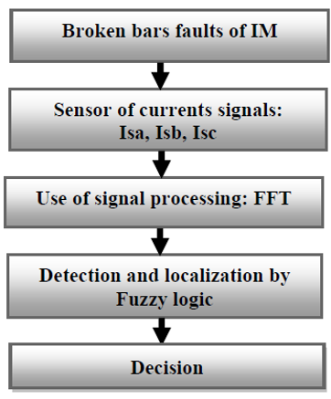
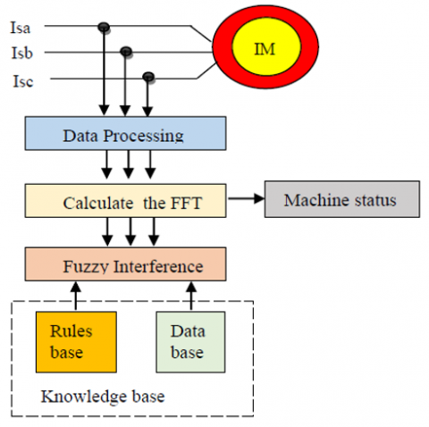
When faults occur in the machine for example (Breaking of the bars), using Signal Sensor for electrical and mechanical magnitude measurements, during the operation of a machine to determine if there is a fault. Then applying the signal processing techniques of the signal to reveal the signatures of the faults and the extraction of the information is necessary to identify several types of faults by a technique, namely: spectral analysis 'FFT'. Then using fuzzy logic to detect and locate faults. Finally, in the failure detection phase, it is necessary to decide whether a fault exists or not, see Figure 1. Shows the general diagram for fault diagnosis [14, 15].
Figure 1. General scheme for fault diagnosis based Fuzzy logic
3.1 Fast fourier transform (FFT)
Fourier analysis makes it possible to know the different frequencies existing in a signal, that is to say, its spectrum, but does not make it possible to know at what instants these frequencies were emitted. This analysis gives global and not local information. The Fourier analysis does not allow the study of signals whose frequency varies over time. Such signals require the establishment of a time-frequency analysis which will allow localization of the periodicities over time and will, therefore, indicate if the period varies continuously if it disappears then reappears subsequently, Where it is given by the following relation [16]:
$X(t)=\int_{-\infty}^{\infty} x(t) e^{-2 \pi f} d t$ (18)
Its inverse is given by:
$X(f)=\int_{-\infty}^{\infty} x(f) e^{-2 \pi f} d f$ (19)
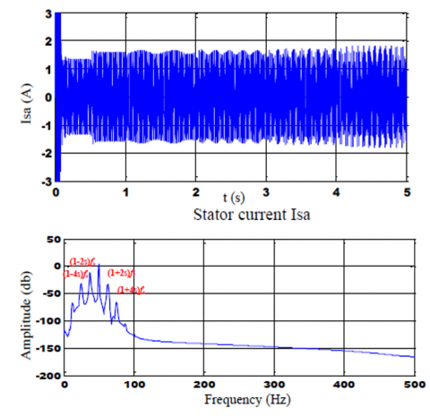
The spectral component associated with broken rotor bars is found at the frequency, by relation (1± 2sk)fs.
where,
s: is the per-unit motor slip,
fs: is the frequency of the power grid in which the motor is connected and k: is the number of the broken bar.
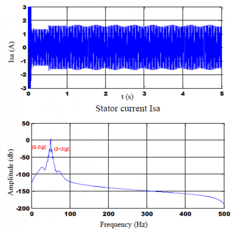
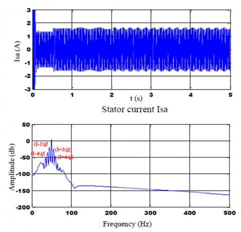
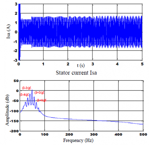
These two frequencies (1-2s)fs and (1+2s)fs, which allow broken rotor bars can be detected by monitoring current spectral components. Using the stator currents Isa phase ‘a’ and follow the machine's behavior in different states healthy and faults (broken one bar, broken two bars, broken three bars, broken four-bar). Frequency spectrum analysis of the current around 50Hz, we note for Figure 1 no lateral line in the healthy state, on the other hand in the fault type breakage of the bars adjacent to Figures 2-6, we observe a lateral line in the vicinity of the fundamental 50 Hz. In our case, the increase in the number of broken bars N° (1, 2, 3 and 4), occurs growth in the values of the amplitude of the lines according to the equation (1 ± 2sk) fs.
Figure 2. Spectral stator current for healthy machine
Figure 3. Spectral stator current with one rotor broken bar
Figure 4. Spectral stator current with two rotor broken bars
Figure 5. Spectral stator current with three rotor broken bars
Figure 6. Spectral stator current with four rotor broken bars
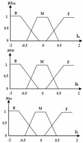
To monitor the behavior of the machine by studying the FFT current indicators, digital data is represented as linguistic information. These functions are determined practically after analysis of the performance of the machine (through the simulation of the healthy and/or faulty model). The schema of the working of fuzzy logic is shown in Figure 7. We take as output variable (LM) and as the input the current variable (Isa, Isb, and Isc). Note that for the output variable the membership functions corresponding to four fuzzy subsets are: S: Healthy, D: Fault, DE: Failure P: Seriously Damaged as shown in Figure 8. And each input variable is transformed into linguistic quantity with three subs - fuzzy set B: Low, M: Medium, F: Strong, as shown in Figure 9. Using the triangular, trapezoidal functions for the three input variables, the fuzzy logic theory, the three stator current inputs, and the machine state output are given as following [17]:
• Inputs
$\left\{\begin{array}{l}I_{s a}=\left\{\mu_{I_{s a}}\left(i_{s a j}\right) / i_{s a j} \epsilon I_{s a}\right\} \\ I_{s b}=\left\{\mu_{I_{s b}}\left(i_{s b j}\right) / i_{s b j} \epsilon I_{s b}\right\} \\ I_{s c}=\left\{\mu_{I s_{c}}\left(i_{s c j}\right) / i_{s c j} \epsilon I_{s c}\right\}\end{array}\right.$ (20)
• Output
$L M=\left\{\mu_{L M}\left(l f_{i}\right) / l f_{j} \epsilon L M\right\}$ (21)
Figure 7. Basic diagram for diagnostics
Figure 8. Membership functions for output variables
Figure 9. Membership functions for the input variable
Inferences link the measured quantities and the output variables by linguistic rules. A fuzzy rule, in this case, is the combination of symptoms and defects. In the case of diagnosis, these rules must group the failures, suffered by the induction machine, associated with their symptoms, the fuzzy logic process consists of two parts are the data acquisition and the design of the rules. To analysis these symptoms it is necessary to use the algorithms of Mamdani.
For the fuzzy inference, we chose of Mamdani method based on the Max-Min inference method. where this method carries out the operator "AND" by the function "Min", the conclusion "THEN" of each rule by the function "Min" and the connection between all the rules (operator "OR") by the function Max.
The name of this method, called Max-Min or "Mamdani implication", is due to the way of performing the THEN and OR operators of the inference.
Inputs to a fuzzy system are generally measured using measuring devices which are most often of the analog type. Since the implementation of the fuzzy system is almost always done digitally, it is first necessary to provide for an analog/digital conversion. When implementing this conversion, adaptation factors must be introduced which take into account the format chosen for the converted quantities.
This conversion is linked on the one hand to a quantification of the signals, because of the finite length of the digital quantities, and on the other hand to a sampling. Assigning degrees of belonging to each input value is a transition from physical quantities to linguistic values.
Linguistic variables are defined by their linguistic values. In our study case, we have corresponded to the input variables (Ia, Ib, and Ic) membership functions which in general are triangles or trapezoids. These functions are determined empirically after analysis of the functioning of the system (through the simulation of the healthy and / or faulty model). For each variable we define zones in fuzzy sets as follows (low, medium, strong). The inputs and outputs of the system are defined using the theory of fuzzy logic as follows:
The set of measured values of the universe of the measurable quantities is Isa, sb, sc = {B: Low, M: Medium, F: Strong}.
The state of the engine, LM, is chosen as being the output of the fuzzy system with LM = {S: Healthy, D: Default, DE: Failure P: Seriously Damaged}.
Inferences link the measured quantities and the output variables by linguistic rules. A fuzzy rule, in this case, is the combination of symptoms - faults.
The rules used are of type:
If < Isa = Small > AND < Isb = Large > then <fault LM = Large.
The fuzzy rules are in general indicated on the if-then formula used in the study system can be summarized as follows:
Rule (1): if Isa is B and Isb is B and Isc is B Then LM is P
Rule (2): if Isa is B and Isb is B and Isc is M Then LM is DE
Rule (3): if Isa is B and Isb is B and Isc is F Then LM is P
Rule (4): if Isa is B and Isb is M and Isc is B Then LM is DE
Rule (5): if Isa is B and Isb is M and Isc is M Then LM is D
Rule (6): if Isa is B and Isb is M and Isc is F Then LM is DE
Rule (7): if Isa is B and Isb is F and Isc is B Then LM is P
Rule (8): if Isa is B and Isb is F and Isc is M Then LM is DE
Rule (9): if Isa is B and Isb is F and Isc is F Then LM is P
Rule (10): if Isa is M and Isb is B and Isc is B Then LM is P
Rule (11): if Isa is M and Isb is B and Isc is M Then LM is D
Rule (12): if Isa is M and Isb is B and Isc is F Then LM is DE
Rule (13): if Isa is M and Isb is M and Isc is B Then LM is D
Rule (14): if Isa is M and Isb is M and Isc is M Then LM is S
Rule (15): if Isa is M and Isb is M and Isc is F Then LM is DE
Rule (16): if Isa is M and Isb is F and Isc is B Then LM is DE
Rule (17): if Isa is M and Isb is F and Isc is M Then LM is DE
Rule (18): if Isa is M and Isb is F and Isc is F Then LM is P
Rule (19): if Isa is F and Isb is B and Isc is B Then LM is P
Rule (20): if Isa is F and Isb is B and Isc is M Then LM is DE
Rule (21): if Isa is F and Isb is B and Isc is F Then LM is P
Rule (22): if Isa is F and Isb is M and Isc is B Then LM is DE
Rule (23): if Isa is F and Isb is M and Isc is M Then LM is DE
Rule (24): if Isa is F and Isb is M and Isc is F Then LM is P
Rule (25): if Isa is F and Isb is F and Isc is B Then LM is P
Rule (26): if Isa is F and Isb is F and Isc is M Then LM is P
Rule (27): if Isa is F and Isb is F and Isc is F Then LM is P
When correctly processing the breakout data of the adjacent bars and then using fuzzy membership functions and rules, which reduces the cost of fault diagnosis and improves efficiency. The following Figure 10 shows the role of fuzzy logic for diagnosing the faults by introducing the FFT technique to extract the indicators of these signals. Then using fuzzy logic to make decisions on the state of the machine in case of healthy or defect and represent the values of the membership function of the input and output variables.
Figure 10. Diagram general for diagnostics the faults
This method consists in taking the abscissa corresponding to the center of gravity of the membership function. Formally, it is expressed by the following formula [18, 19]:
$X^{*}=\frac{\int_{x_{0}}^{x_{1}} x \cdot U(x) \cdot d x}{\int_{x_{0}}^{x_{1}} U(x) \cdot d x}$ (22)
This method gives much better results and is also widely used in fuzzy systems. However, it has the disadvantage of being very expensive. Indeed, to apply this method of Defuzzification, it is necessary to calculate the center of gravity of the surface (see Figure 11) under the membership function and to take the abscissa of this center of gravity. To do this, you need to break down the membership function into small pieces and integrate each piece [20, 21].
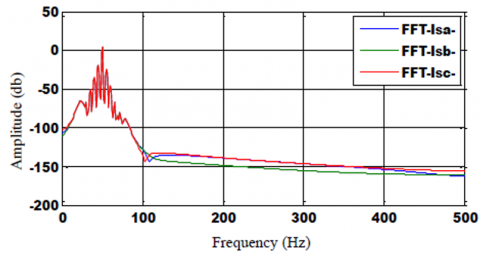
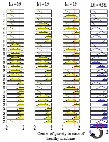
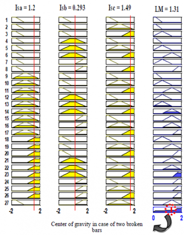
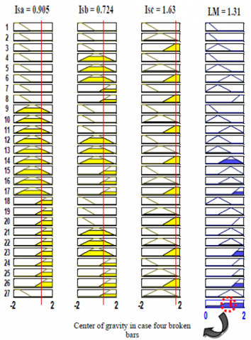
When using signal processing the four broken bars by fuzzy logic, which introduce the role fuzzy logic for detecting and locating the faults. Using the FFT technique to extract the indicators of these signals that their use to make decisions on the state of the machine in case of healthy or defect. These represent the values of the membership function of the input and output variable. The Figures 12-16 below represent a current of the stator by using fast Fourier Transform algorithm (FFT) represented of stator currents (FFT-Isa, FFT-Isb, FFT-Isc) which will be used as indicator values in the fault diagnosis system and the fuzzy logic for the healthy state and various rotors faults (breakage of four bars) and with machine supplied directly by the three-phase network. We apply a load of Cr = 3.5 Nm, at t = 0.5s, the value of the resistance of the broken bars will be considered equal to eleven (11) times. To examine the efficiency of the fuzzy logic system, we use the current of the stator to study the behavior of the machine in healthy and fault breakage of the rotor bars. In this case, the stator current is transformed to the frequency domain using a Fast Fourier Transform algorithm (FFT), which depends on signal analysis in the frequency domain. Then extract the amplitudes in case of four broken adjacent bars. The Figures 17-21, presents fuzzy inference for output Values. These values represent the center of gravity calculated in each of case of healthy and faulty (four broken bars) by tracking the developments of the three currents (Isa, Isb, Isc) and the state of the machine (LM) according to the following stages:
*Input the currents (Isa=0.9, Isb=0.9, Isc=0.9).
Output LM=0.681
*At t = 1s one broken bar
Input the currents (Isa=1.26, Isb=0.148, Isc=1.41)
Output LM=1.29
* At t = 2s two broken bars
Input the currents (Isa=1.2, Isb=0.293, Isc=1.49)
Output LM=1.31
* At t = 3s three broken bars
Input the currents (Isa=1.37, Isb=0.12, Isc=1.49)
Output LM=1.35
* At t = 4s four broken bars
Input the currents (Isa=0.905, Isb=0.724, Isc=1.63)
Output LM=1.31
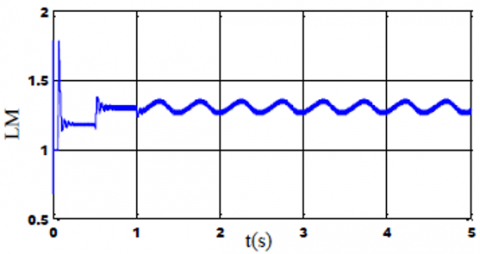
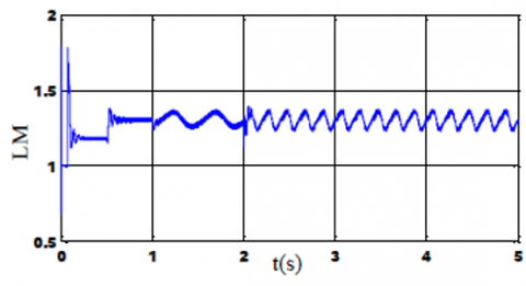
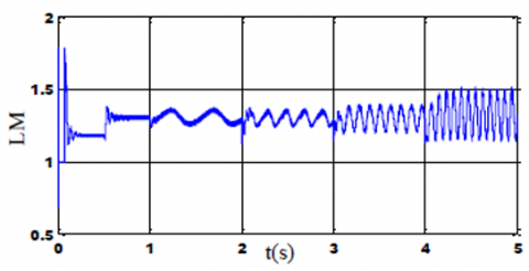
Then we move on towards the fuzzy logic which translates the three stator current (Isa, Isb, Isc) considered as input variables in the fuzzy system and the condition of the machine (LM) is considered as an output variable for the detection and diagnosis of broken bar faults (the decision). The advantages of fuzzy logic are illustrated by the approximate reasoning capacity when a fault occurs and capable of separating and identifying the faults according to time as shown in Figures 22-26, we notice an increase in the undulations of the current stator and increases according to the number of broken bars. As shown in Table 1.
Table 1. Value calculated in center of gravity
|
Type faults |
One bar |
Tow bars |
Three bars |
Four bars |
|
Output fuzzy Values LM |
1.37 |
1.38 |
1.4 |
1.5 |
Figure 11. Defuzzification by the center of gravity
Figure 12. FFT of the stator currents (Isa- Isb- Isc) in healthy case
Figure 13. FFT of the stator currents (Isa- Isb- Isc) in case one broken bar
Figure 14. FFT of the stator currents (Isa- Isb- Isc) in case two broken bar
Figure 15. FFT of the stator currents (Isa- Isb- Isc) in case three broken bars
Figure 16. FFT of the stator currents (Isa- Isb- Isc) in case four broken bars
Figure 17. Fuzzy inference for Output Values in case of a healthy machine
Figure 18. Fuzzy inference for Output Values in case of one broken bar
Figure 19. Fuzzy inference for Output Values in case two broken bars
Figure 20. Fuzzy inference for Output Values in case broken three bars
Figure 21. Fuzzy inference for Output Values in case of four broken bars
Figure 22. System output of fuzzy in the healthy case
Figure 23. System output of fuzzy in case of one broken bar
Figure 24. System output of fuzzy in case broken two bars
Figure 25. System output of fuzzy in case of three broken bars
Figure 26. System output of fuzzy in case of four broken bars
Recent technological developments in fault diagnosis in induction machines become the most widely used in the field of control systems. However, fault detection and diagnosis through the use of modern methods allow us to monitor and control by taking preventive measures to detect these sudden accidents. The proliferation of electrical disturbances is due to an increase in the number of faults that occur in the machine for example: break of bars.
Monitoring a machine comprises diagnosing faults by detecting an abnormal transposition in the behavior or state of a system and in locating its cause. The aim is to guarantee security and continuity of service and to record events useful for curative maintenance or feedback. In this paper, we presented the induction machine fault by using the multi-winding model for simulation of broken bars.
The proposed detection technique could be used by artificial intelligence represented fuzzy logic (FL) based on Fast Fourier Transform (FFT) for extracting the necessary information to identify faults. Depending on the center of gravity. This method gives much better results and is also widely used in fuzzy systems. These results signify that the proposed fuzzy logic has great importance and a better way with signal and the uncertainties for fault determination. Finally, this technique is a simple and effective tool to implement diagnosis in the early stage.
This work was supported by Electrical Engineering Laboratory (LGE), at the University of Mohamed Boudiaf- M’sila, (Algeria). We like to thank Dr. Djalal Eddine Khodja and Dr. Salim Chakroune for their help in the preparation of this paper.
Appendix for simulation broken bar
|
Symbol Definition Value |
|||
|
Pn |
output power |
1.1 |
kW |
|
Vs |
stator voltage per phase |
220 |
V |
|
Fs |
stator frequency |
50 |
Hz |
|
p |
poles pair number |
1 |
|
|
Rs |
stator resistance |
7.58 |
Ω |
|
Rr |
rotor resistance |
6.3 |
Ω |
|
Rb |
rotor bar resistance |
0.15 |
m Ω |
|
Re |
resistance of end ring segment |
0.15 |
m Ω |
|
Lb |
rotor bar inductance |
0.1 |
μH |
|
Le |
inductance of end ring |
0.1 |
μH |
|
Lsf |
leakage inductance of stator |
0.0265 |
H |
|
Nr |
number of rotor bars |
16 |
|
|
Ns |
number of turns per stator phase |
160 |
|
|
J |
moment of inertia |
0.0054 |
kg m2 |
|
e |
Air-gap mean diameter |
2 |
mm |
[1] Boubaya, N., Saad, B., Maazouz, M. (2016). Radial active magnetic bearing control using fuzzy logic. AMSE JOURNALS-2016-Series: Modelling A, 89(1): 92-100.
[2] Leonidopoulos, G. (2016). Modelling and simulation of electric power transmission line current as wave. AMSE JOURNALS-2016-Series: Modelling A, 89(1): 1-12.
[3] Shuai, Z., Peng, Y., Liu, X., Li, Z., Guerrero, J.M., Shen, J. (2019). Parameter stability region analysis of islanded microgrid based on bifurcation theory. IEEE Transactions on Smart Grid, 10(6): 6580-6591. https://doi.org/10.1109/TSG.2019.2907600
[4] Bednarz, S., Dybkowski, M. (2019). Induction motor windings faults detection using flux-error based MRAS estimators. Diagnostyka, 20(2): 87-96. https://doi.org/10.29354/diag/109092
[5] Seera, M., Chee Peng, L., Ishak, D., Singh, H. (2012). Fault detection and diagnosis of induction motors using motor current signature analysis and a hybrid FMM - CART model. IEEE Transactions on Neural Networks and Learning Systems, 23(1): 97-107. https://doi.org/10.1109/TNNLS.2011.2178443
[6] Amezquita-Sanchez, J.P., Valtierra-Rodriguez, M., Perez-Ramirez, C.A., Camarena-Martinez, D., Garcia-Perez, A., Romero-Troncoso, R.J. (2017). Fractal dimension and fuzzy logic systems for broken rotor bar detection in induction motors at start-up and steady-state regimes. Measurement Science and Technology, 28(7): 1-29. http://doi.org/10.1088/1361-6501/aa6adf
[7] Karnavas, Y.L., Chasiotis, I.D., Vrangas, A. (2017). Fault diagnosis of squirrel-cage induction motor broken bars based on a model identification method with subtractive clustering. IEEE 11th International Symposium on Diagnostics for Electrical Machines, Power Electronics and Drives (SDEMPED), 1: 304-310. https://doi.org/10.1109/demped.2017.8062372
[8] Merabet, H., Bahi, T., Drici, D., Halam, N., Bedoud, K. (2017). Diagnosis of rotor fault using neuro-fuzzy inference system. Journal of Fundamental and Applied Sciences, 9(1), 170-182. http://doi.org/10.4314/jfas.v9i1.12
[9] Prins, S., Mini, V.P., Mayadevi, N., Harikumar, R. (2018). Detection of broken rotor bars using multilevel wavelet decomposition. 2nd International Conference on Trends in Electronics and Informatics (ICOEI). http://doi.org/10.1109/ICOEI.2018.8553821
[10] Menacer, A., Nait-Said, M., Drid, S. (2004). Stator current analysis of incipient fault into asynchronous motor rotor bars using fourier fast transform. Journal of Electrical Engineering, 55(6): 122-130.
[11] Kechida, R., Menacer, A., Benakcha, A. (2010). Fault detection of broken rotor bars using stator current spectrum for the direct torque control induction motor. World Academy of Science, Engineering and Technology, 1230-1235.
[12] Khalaf, S.G., Mohamed, H. (2010). Diagnosis and fault tolerant control of the induction motors techniques a review. Australian Journal of Basic and Applied Sciences, 4(2): 227-246.
[13] Kechida, R., Menacer, A., Benakcha, A. (2010). Fault detection of broken rotor bars using stator current spectrum for the direct torque control induction motor. Journal of Electrical and Computer Engineering, 4(6): 988-993.
[14] Yaghobi, H., Ansari K., Rajabi, H. (2011). Analysis of magnetic flux linkage distribution in salient pole synchronous generator with different kinds of inter turn winding faults. Iranian Journal of Electrical & Electronic Engineering, 7(4): 260-272.
[15] Nemec, M., Ambrožič, V., Fišer, R., Nedeljković, D., Drobnič, K. (2019). Induction motor broken rotor bar detection based on rotor flux angle monitoring. Energies, 12(5): 794-811. https://doi.org/10.3390/en12050794
[16] Rababaah, A.R., Arumala, J., Dabipi, I.K., Fotouhi, K., Hura, G., Dudi, A. (2016). Mechanical system fault detection using intelligent digital signal processing. Journal of Machinery Manufacturing and Automation, 5(1): 27-39.
[17] Filippetti, F., Franceschini, G., Tassoni, C., Vas, P. (2000). Recent developments of induction motor drives fault diagnosis using AI techniques. IEEE Transactions on Industrial Electronics, 47(5): 994-1004. https://doi.org/10.1109/41.873207
[18] Michael Gr, V. (2015). Defuzzification of fuzzy numbers for student assessement. American Journal of Applied Mathematics and Statistics, Electronics, 3(5): 206-210. https://doi/ 10.12691/ajams-3-5-5
[19] Užga-Rebrovs, O., Kuļešova, G. (2017). Comparative analysis of fuzzy set defuzzification methods in the context of ecological risk assessment. Information Technology and Management Science, 20(1): https://doi.org/10.1515/itms-2017-0004
[20] Fawzi, G., Chemseddine, R., Djamel, B., Boualem, M. (2019). Bearing fault diagnosis based on feature extraction of empirical wavelet transform (EWT) and fuzzy logic system (FLS) under variable operating conditions. Journal of Vibroengineering, 21(6): 1636-1650. https://doi.org/10.21595/jve.2019.20092
[21] Anjana, P., Jeena, T. (2015). Performance assessment for students using different defuzzification technique. IJIRST–International Journal for Innovative Research in Science & Technology, 2(6): 43-53.