Mohamed Asaad Abdelrazik* | Amir Taher Elsheikh | Mohamed A. Zayan | Abo-Bakr M. Elhady
OPEN ACCESS
The development of complex systems with multiple constraints is the research hotspot in recent decades. The models-based systems engineering (MBSE) methodologies are often adopted to develop such systems, but they cannot cover all system development dimensions (SDDs). Therefore, this paper attempts to propose a new methodology for developing the said systems, aiming to minimize development time and cost and maximize system quality, orgaizational efficiency and user satisfaction. The transdisciplinary quality system development lifecycle (TQSDL) model was modified to serve as a generic MBSE methodology. Both Quality Function Deployment (QFD) and the dependency structure matrix (DSM) were integrated into the TQSDL process. The proposed MBSE methodology fully cover all SDDs, the roles of the Systems Engineering Manager (SEM) and the systems engineering (SE) processes. In addition, the methodology enables developers to estimate the changes of development cost induced by changing user demands.
transdisciplinary quality system development lifecycle (TQSDL) model, model-based systems engineering (MBSE), dependency structure matrix (DSM), quality function deployment (QFD), systems engineering (SE)
Rapid variations in the world economy and technology have put excessive pressures on designers or decision makers to create new methodologies that used to develop the systems. The variations that have the greatest effect on the systems development are the growth in the size and complexity of the systems, which required in the market today. Furthermore, the increase in the rate of change in customer needs with which the development organizations must quickly implement to get a competitive advantage. Generally, the development of these large complex systems requires the implementation of technical activities along with managerial activities. Hence, these two groups of activities have to be combined in one approach to facilitating the development process.
Systems Engineering (SE) discipline is a structured approach that integrates the above activities to deal with the development processes [1]. Traditionally, large systems were developed using a document-based system engineering approach to achieve SE activities [2]. This approach is characterized by the development of many documents either specifications or design in electronic file format or hard copy, which are exchanged between stakeholders [1]. The document-based approach has some limitations as [2]:
(1) Completeness and relations between stakeholders’ needs, requirements, design, and verification are hard to evaluate because of the propagation of information across several documents.
(2) Difficulty to maintain the documentation synchronized with the update of the design.
(3) Traceability and change management are difficult to implement.
(4) Poor relationship between the high level of system requirements and lower level requirements for software and hardware.
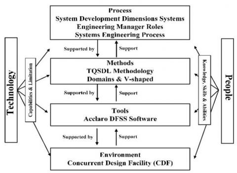
All of these limitations will affect the quality of the final system. Consequently, MBSE has been used to overcome these limitations. MBSE considers as a recipe and defined as a collection of process, methods, and tools within a certain environment as shown in Figure 1 [3]. This approach has been used by engineering disciplines (electrical, mechanical) for decades to support the process of product development. SE is one of the recent engineering disciplines that used model-based in its work.
Figure 1. MBSE methodology elements
Generally, MBSE depends on a graphical language and is used to generate the system details related to requirements, design, verification, and validation. Moreover, it provides a chance to overcome the limitations of the document-based approach. The main benefits of MBSE are as follows [1]:
(1) Enhanced communications between stakeholders.
(2) Improved the capability of managing the complexity of systems.
(3) Reduced risk during development.
(4) Increased system quality.
(5) Improved the capability to capture the knowledge and reuse the information in more standardized ways.
(6) Reduced schedule time and development costs.
(7) Supported system developers to more efficiently assess the impact of changes in the design.
(8) Enhanced the capability to learn and teach SE fundamentals.
There are many MBSE had been developed such as IBM Telelogic Harmony, INCOSE Object-Oriented Systems Engineering Method (OOSEM), IBM Rational Unified Process (RUP SE), and Vitech [3]. However, these methodologies were not able to cover all SDD processes. This is one of the most important problems encountered by the users of these methodologies during the development of complex systems.
To solve this problem, this paper establishes a new MBSE methodology that covers all the missed processes during the development of large complex systems.
Table 1 summarizes the MBSE methodologies that have been established. As well as it provides a comparison between these methodologies and the new generic MBSE methodology that is proposed in this study.
Thus, the MBSE methodologies have become more and more accepted as well as they can be the basis for superior management of the whole system development processes. The new proposed MBSE methodology in this study is based on the TQSDL model which was developed in 2107 [4]. During the development of this new MBSE, it has taken into account four aspects:
(1) System development dimensions (SDD).
(2) Systems engineering manager’s roles.
(3) Systems engineering process.
(4) The previously established MBSE methodologies.
To develop the new generic MBSE methodology, which achieves the above aspects, the following actions have been taken:
(1) Modify the TQSDL model domains in order to cover all the SDD. Hence, the TQSDL model process will be modified also.
(2) Integrate the DSM and QFD into the TQSDL process to enhance the system development process as well as to support the SEM to estimate the change in the development cost due to the change in stakeholder needs.
The reminder of this study is organized as follows: Section 2 presents overview on the transdisciplinary quality system development lifecycle (TQSDL) methodology aspects. Section 3 introduce TQSDL methodology domains in brief. Section 4 presents the new proposed theorems. Section 5 explains the new MBSE methodology process. Section 6 presents the proposal for the environment in which the new MBSE will be worked followed by the conclusion in Section 7.
Table 1. Comparison between the new proposed methodology and leading MBSE
|
Item |
Harmony SE |
INCOSE OOSEM |
RUP SE |
Vitech CORE |
New proposed methodology |
|
Identify stakeholders |
|
|
|
|
√ |
|
Collect needs from all stakeholders |
|
|
|
|
√ |
|
Analyze stakeholders needs |
|
√ |
|
|
√ |
|
Define system requirements |
√ |
√ |
√ |
√ |
√ |
|
Analysis system requirements |
√ |
√ |
√ |
√ |
√ |
|
Function requirements analysis |
√ |
|
|
√ |
√ |
|
Analyze design (uncouple, decouple, couple) |
|
|
|
|
√ |
|
Define tasks interactions |
|
|
|
|
√ |
|
Develop system architecture |
√ |
√ |
|
√ |
√ |
|
Synthesis of architecture |
|
√ |
|
|
√ |
|
Analysis of physical interactions |
|
|
|
|
√ |
|
Optimize and evaluate alternatives |
|
√ |
|
|
√ |
|
Identify supplier |
|
|
|
|
√ |
|
Analysis of suppliers |
|
|
|
|
√ |
|
Validate and verify system |
|
√ |
√ |
√ |
√ |
|
Be able to integrate with SE tools |
|
|
|
|
√ |
|
Graphical modeling language |
√ |
√ |
√ |
√ |
√ |
|
Mathematical foundation |
|
|
|
|
√ |
|
Allow back and forward traceability from identified stakeholders to the verification method |
|
|
|
|
√ |
|
Provide a framework for SEM |
|
|
|
|
√ |
|
Total processes |
5 |
8 |
4 |
6 |
20 |
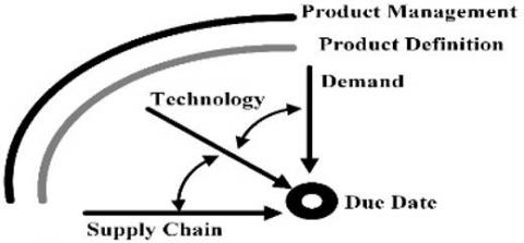
Change in the developed systems is very significant for endurance in a fast-moving market. Consequently, high responsibilities will be put on the people interested in the system development to compete in this environment. Each new system is a new chance for the organization to succeed. Traditionally, organizations compete in the market by using new technologies only in the developed systems. But this is not enough to be the leader in the market. Therefore, the organization has to be good in all SDD. System development can be seen in three dimensions [5] (Figure 2):
(1) Demand dimension, which is the activities that interact with the stakeholders to create the demands of the developed system.
(2) Technology dimension, which is the system functional view and how to fulfill these functions.
(3) Supply dimension, which is the activities that clarifying the connection between the suppliers, manufacturer, distributor, retailer, customer, and service center.
Figure 2. System development dimensions
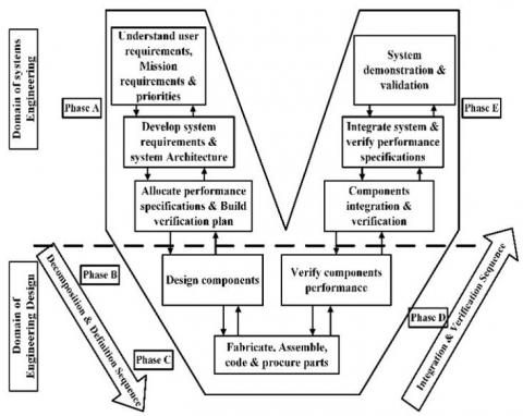
Figure 3. Vee model
Figure 4. The PMTE elements of TQSDL methodology
Concerning SEM roles aspect, there are ten different roles have to be performed by SEM during the development process of complex systems. These roles are abridged as follows [6]:
(1) Identification of stakeholders’ needs and the linkage between them.
(2) Requirements Management (RM) and Change Management (CM).
(3) Architecture and control the design of large systems.
(4) Integration.
(5) Analysis and testing.
(6) Process management.
(7) Risk and technical management.
(8) Leading, coordinating, and managing.
(9) Logistics and supply management.
(10) Information management.
Concerning the SE process, complex systems have been created through the use of various system lifecycle models. These models are helpful in describing the beginning, end and tasks suitable to the system lifecycle phases [1]. Vee model is one of these models that had been proposed by Forsberg and Mooz to cover the whole system development processes as well as the technical aspect of the project lifecycle as shown in Figure 3.
As mentioned previously, the MBSE methodology is a recipe and can be defined as a collection of process, methods, and tools within a certain environment. Accordingly, to develop a new MBSE methodology, its elements must be configured. Figure 4 presents the elements of the new proposed MBSE methodology, which will be named as Transdisciplinary Quality System Development Lifecycle (TQSDL) Methodology. In the rest of this study, the elements of the TQSDL methodology will be described. Actually, the first element, process (what) element, has been described in Section 2.
In order to cover the SDD and managing the neglected processes in the established methodologies such as stakeholder management, supplier management, and development cost management the TQSDL model which was developed in 2017 [4] will be modified as follows:
(1) The Customer Domain (CD) has been changed to Need Domain (ND) with Stakeholder Need {SN} and Critical to Quality {CTQ} characteristic vectors.
(2) The Supply Domain (SuD) with Supplier Identification characteristic vector {SUPI} has been added.
(3) The system Component Cost {SCC} has been added to Physical Domain (PD).
(4) Two new theorems have been created to illustrate and control the process of mapping between the characteristic vectors of ND as well as the mapping between the PD and SuD.
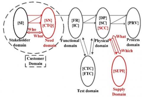
Figure 5 illustrates the domains of the TQSDL methodology that are used to cover all the SDD. The red colour represents the differences that occurred in the TQSDL model.
In the ND domain, the Customer Need (CN) characteristic vector has been changed to Stakeholder Needs {SN} to address the needs of all stakeholders not only customers. Stakeholder needs are statements that are collected from all stakeholders to obtain a figure out about the system. These statements contain the capability and constraints parameters of the system but in the stakeholders’ language. The stakeholders’ needs are the main challenge with the need domain because some stakeholders are not specialist. Therefore, the designer must work with stakeholder to translate these needs into functional requirements. In order to solve this challenge a new characteristic vector called Critical to Quality {CTQ} will be added to ND to translate the vague {SNs} into technical quantitative and measurable terms. The mapping between {SNs} and {CTQs} as well as the {CTQs} and Functional Requirements {FRs}, Input Constraints {ICs} can be mathematically expressed in Equations (1), (2), and (3), respectively as follows:
$\{S N\}=[Q]\{C T Q\}$ (1)
$\{C T Q\}=[N]\{F R\}$ (2)
$\{C T Q\}=[C]\{I C\}$ (3)
Figure 5. TQSDL methodology domains
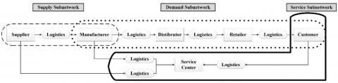
As mentioned before, there are three dimensions must be covered during the System Development Lifecycle (SDL). The TQSDL model does not cover the supply dimension. The supply dimension is often represented as a network that connects between supplier, manufacturer, distributor, retailer, customer, and service centre. This network can be separated into three sub-networks: demand, supply, and service as shown in Figure 6.
In the TQSDL methodology, the Supply Domain (SuD) has been added to the TQSDL model domains to cover the supply dimension. This domain is featured by the supplier identification vector {SUPI}. The SuD focuses on the supply sub-network (as shown in the dashed domain in Figure 6 and its interaction with the PD as illustrated in Figure 5 The linkage between PD and SuD is what (each component) to which (each supplier). Equation (4) presents the mathematical formula of the linking between System Components vector {SC} and {SUPI}.
$\{S C\}=[S C A]\{S U P I\}$ (4)
The main benefits of adding SuD are:
(1) Reduces the supply risks.
(2) Visualizes the relationships between all suppliers and SCs.
(3) Minimizes the opportunistic behaviour of suppliers.
(4) Encourages suppliers to improve their performance.
In the TQSDL methodology, improving the credibility of managing the changes in the development cost are one of the main objectives of this methodology. System component cost {SCC} is a new characteristic vector that is added to PD to get the cost breakdown structure (CBS) of the {SCs}. This new vector will be used to predict the variations in the materials cost (part of the development cost) due to the variations in the {FRs} and their corresponding {DPs}. Furthermore, it will help to offer a clear view of the cost of each {DP} through the direct mapping between {DPs} and {SCC}. This view will present the initial perception of the effect of DPs changes on the development cost. Equation (5) presents the mathematical formula of the {DPC}.
$\{D P C\}=[S S]\{S C C\}$ (5)
The rest of the mathematical formulas that represent the mapping between TQSDL methodology characteristic vectors are presented in Equations (6) to (12) as follows:
{SI}=[SA]{SN} (6)
{FR}=[A]{DP} (7)
{IC}=[CA]{DP} (8)
{DP}=[SS]{SC} (9)
{SC}=[P]{PRV} (10)
{SC}=[CT]{CTC} (11)
{FR}=[FT]{FTC} (12)
Figure 6. Supply dimension networks
Generally, the Axiomatic Design (AD) theory started with two axioms. These axioms consider as guidelines for the system developers. Prof. Suh presented several theorems and corollaries based on the AD axioms to facilitate the mapping process between the domains [7].
In 2008, Gumus modified the AD by adding the test domain to develop the Transdisciplinary System Development Lifecycle (TSDL) model [8]. Moreover, seven theorems were developed to complement the theorems of AD. These seven theorems have an important effect on the continued implementation of AD.
In 2017, the TSDL model has been modified by adding the stakeholder domain (SD) to develop the TQSDL model [4]. A new theorem was created to control the process of mapping and zigzagging between the SD and CN domain.
Similarly, in the TQSDL methodology, two new theorems are created to supplement the previously theorems of AD, TSDL model, and TQSDL model. These theorems are used to control the process of mapping between:
(1) The vectors in the need domain.
(2) The physical domain and the supply domain.
The new theorems can be stated as follows:
Theorem 1 (Mapping Need vector {SN} to Critical to Quality vector {CTQ}): Since the stakeholder needs have been collected, they should be mapped to one or more critical to quality parameters that represents the means of attaining stakeholder satisfaction.
Theorem 2 (Allocate system components vectors {SC} to supplier identification vector{SUPI}): The system components vector {SC} is allocated to supplier identification vector {SUPI} without restricting to independence axiom. Multiple system components allocate to one supplier or several suppliers mapping to one system component.
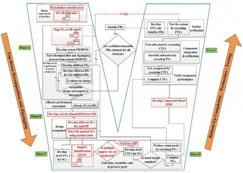
As presented in section 2, there are many processes missing in the previously established MBSE methodologies, which often lead to weakness in technical management process through the SDL and hence will effect on achieving the roles of SEM. The objective of this section is to present the TQSDL processes, which are tasked with providing a solution to SEM to perform his/her roles. Moreover, to mold the theoretical description of TQSDL methodology domains into a complete implementable sequence. A roadmap of the TQSDL methodology processes is presented in a V-shaped process as depicted in Figure 7.
Figure 7. Proposed TQSDL process
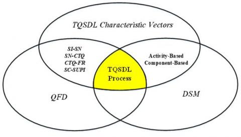
The TQSDL methodology process has three components that presenting the intersection of the TQSDL characteristic vectors, QFD, and DSM as depicted in Figure 8. These tools individually have presented massive concern in the engineering field. Consequently, the TQSDL methodology process gains additional strength by integrating these tools to address the missing processes that were appeared in the previously established MBSE methodologies. The TQSDL process concentrates on developing a comprehensive process that uses its components to cover all the roles of SEM, including SE process.
Figure 8. TQSDL methodology process elements
The TQSDL methodology phases cover all the SDL and compatible with the NASA project lifecycle. The QFD and DSM are integrated into the TQSDL methodology process as follows:
(1) In phase A, the mapping from the stakeholder identifications {SIs} to the functional requirements {FRs} is conducted using QFD over three stages. The first stage contains the QFD-1 that represents the mapping from {SIs} to {SNs}. The second and the third stages are obtained from the axiomatic quality idea [9]. The second stage contains the QFD-2 that represents the mapping from {SNs} to quality parameters called critical to quality {CTQs}. These parameters represent the quantitative measure for the {SN}. The third stage (QFD-3) is the mapping from {CTQs} to {FRs}.
(2) In phase B, the DSM will be used to obtain activity-based DSM as well as component-based DSM in phase D.
(3) In phase C, the QFD-4 will be developed to map from {SCs} to {SUPIs}.
(4) In phase E, the {CTQs} parameters will be helpful during performing acceptance tests.
Generally, the success in completion of system development tasks depends on the efficiency and performance of the selected team. Special endeavor at the start of any project is needed to create a transdisciplinary team that cooperates to accomplish a required design. SEM will be the leader of this team and responsible for facilitating all challenges facing the transdisciplinary team [2, 10].
The process of TQSDL methodology can be easily implemented by using a software computer package. Acclaro DFSS is a software package that encompasses many tools that can be used by SE to develop complex systems. These tools are executed in the AD framework. Acclaro DFSS helps the transdisciplinary team to:
(1) Implements the AD theorems and corollaries.
(2) Collaborates at the early phase of SDL.
(3) Analyzes the quality of design by using axioms before obligating to any cost.
(4) Tracks the development process from {SNs} to the final system.
(5) Predict the change in cost due to change in {SNs}
(6) Documents the development process.
The detail explanation of the TQSDL processes will be presented in the rest of this section with an illustrative example.
5.1 Stakeholders identities and needs collection
Delivering value to stakeholders is the end goal of SDL [11]. This value varies from one stakeholder to another according to their interest. To deliver this value, each process in the flow of activities towards this end must provide value for successive steps. For example, the gathering of SNs must deliver value to the transdisciplinary team through a complete picture of what the market needs. In a succeeding process, this value will be used to create accurate FRs based on the collected SNs.
Now, the process of system development starts by identifying the stakeholders. Regardless of the method that will be used to identify the stakeholders [12], the outputs will be documented in a stakeholder’s sheet. This sheet contains at least name, location, communication method, role in the project, and the staff assigned to an interview with the stakeholder to gather the needs. A forgotten stakeholder that may appear after or before the project finishes and contributes important needs which have not been realized in the developed system, may cause a serious problem and effect on the success of the project. So, the process of identifying the stakeholders must be performed very carefully. The template for the stakeholders’ sheet is presented in Table 2. This sheet will be issued using the Acclaro software package. Two considerations become immediately significant:
(1) Assigns priorities to the stakeholders and collecting needs.
(2) Clarifies conflicts among needs to produce FRs that satisfying all the stakeholders' needs.
Table 2. Stakeholder sheet
|
Stakeholder No |
[STAKEHOLDER] Last Name |
[STAKEHOLDER] First Name |
[STAKEHOLDER] Location of stakeholder |
[STAKEHOLDER] Role in the project |
[STAKEHOLDER] Communication Method |
[STAKEHOLDER] Staff assigned to do an interview |
|
SI_1 |
||||||
|
.... |
||||||
|
SI_4 |
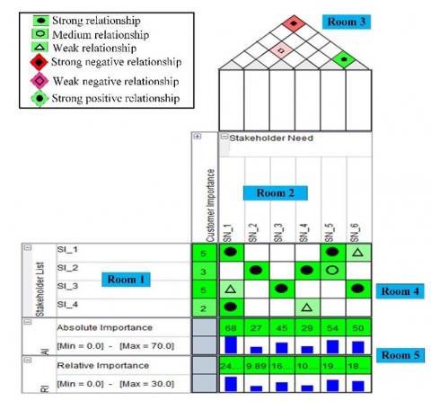
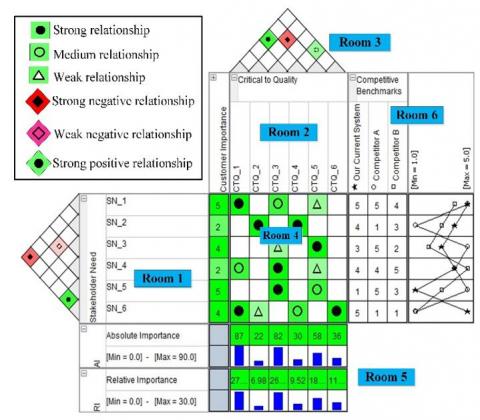
To attain the above consideration, the QFD tool will be used. This tool will provide the following as shown in Figure 9:
(1) Facilitates the prioritization of stakeholders.
(2) Provides a clear visual relationship between {SIs} and {SNs} vectors.
(3) Shows commonalities and conflicts between {SNs}.
(4) Presents the relative and absolute importance of each {SN}.
As the QFD-1 completion, the information that has been gathered and organized must be analysed to obtain the following:
(1) Initially, check room 4 to make sure there are no blank columns or rows. In the case of a row without a mark, it means that there are {SNs} have not been collected. To solve this issue, conduct an interview with the missed stakeholder. In the case of a column without a mark, it means that this {SN} has not been requested from any stakeholder. The accomplishment of this additional {SN} will lead to a growth in the development cost. This additional {SN} will be removed.
(2) Customer importance column indicates the priorities of the stakeholders. Consequently, we can know the stakeholders whose needs must be realized because they will influence on project success.
(3) The relative and absolute importance in room 5 will be used to determine the priorities of the SNs. Consequently, they will help the transdisciplinary team to decide which need should receive the most attention to get the highest degree of stakeholders’ satisfaction.
(4) Room 3 presents the conflicts between stakeholders needs. These conflicts can be categorized as follows:
a. Some can affect the system development that must be resolved immediately.
b. Some can be negotiated with the stakeholders to acquire a compromise solution.
c. Some may exist from stakeholders with little importance and little capability to affect the system development progress. Hence, these conflicts can be overlooked.
Figure 9. QFD-1 Mapping from SIs to SNs
5.2 System requirements and system architectures
Usually, stakeholders express his/her needs in unclear expressions that do not reflect any actionable engineering terms. These unclear expressions mean ambiguity that yields to various interpretations. In TQSDL methodology, the process of mapping from SNs to FRs is divided into two steps based on the axiomatic quality idea [9]. Firstly, translates {SNs} into {CTQs} parameters. Then, translates {CTQs} to {FRs} and {ICs}. Both of these steps will be performed using QFD tool.
5.2.1 Mapping from {SNs} to {CTQs}
Figure 10. QFD-2 mapping from SNs to CTQs
Figure 10 illustrates the translation of {SNs} into {CTQs} parameters. The main benefit of obtaining {CTQs} is to translate the {SNs} into quantitative and measurable terms. Furthermore, these terms will be used as design criteria that can be used later as a checklist when conducting the final acceptance tests for the system as a whole.
As the QFD-2 completion, the data that has been gathered and organized must be analyzed to obtain the following:
(1) Room 4 ensures that all needs have been understood and translated into quantitative parameters. One or more {CTQs} can be developed to address each {SN}.
(2) Relative and absolute importance (room 5) will be used to rank the {CTQs}. This arrangement will help to allocate the resources and to compare between {CTQs}.
(3) Room 6 will identify three important areas:
a. Areas in which you are the best one in the market and you must maintain your place (SN_1, SN_2, SN_6)
b. Areas where you and the competitors are almost on the same level and therefore must struggle to gain a competitive advantage (SN_3,SN_4).
c. Areas where you fall behind and you must try to reach your competitors (SN_5).
(4) System development activities contain many trade-off decisions. Room 3 in QFD supports these activities by identifying the degree of commonalities and conflicts between the {CTQs} if any.
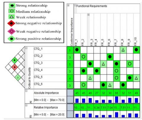
5.2.2 Mapping from {CTQs} to {FRs}
Figure 11. QFD-3 Mapping from CTQs to FRs
In Figure 11, each {CTQ} needs a functional definition. The target is to define a set of FRs (hows) with which the {CTQs} can be materialized. For each {CTQ}, there must be at least one high-level {FR} or {IC} that describe a method of attaining {SNs} and hence will attain stakeholders’ satisfaction.
For each {CTQ}, the transdisciplinary team has to allocate a degree of relationship that reflects the amount to which the defined {FRs} participate to meeting it. The calculated relative and absolute importance present the participation degree of each {FR} to the overall stakeholders’ satisfaction. Furthermore, it can be used to prioritize the FRs.
A major reason for stakeholders’ dissatisfaction is that the developed system has been created away from {SNs}. So, the purpose of mapping from {SNs} to {FRs} through {CTQs} is to develop the system based on the data gathered from stakeholders expectation and current market situations. These data will be translated into quality parameters and technical {FRs}.
Finally, when the QFD-3 construction has been finished, we have got a compilation of:
(1) {SNs} and their priorities.
(2) A quantitative measure for {SNs}.
(3) A competitive assessment of our system in the market.
(4) The mapping between {SIs} and {FRs}.
(5) The trade-off analysis for {SNs} and {CTQs}.
(6) Importance degree for each {FR}.
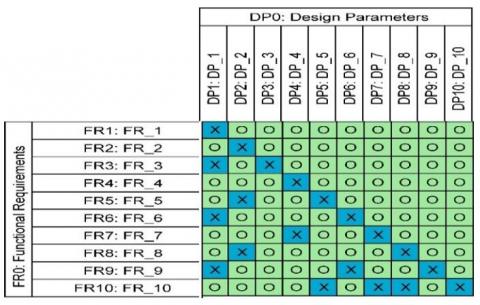
5.2.3 Mapping from {FRs}to {DPs}.
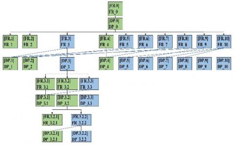
Once the highest-layer of {FRs} and the {ICs} are obtained, they must be investigated to develop the highest-layer of {DP} and {SC} that represents the conceptual solution for the {SNs} and the suggested system as presented in Figure 12. After the highest level of {DPs} has been identified, the {ICs} will be allocated to the {DPs} as shown in Figure 13. After that, the decomposition and zigzagging (D&Z) process will start.
Figure 12. [A] matrix
Figure 13. [CA] matrix
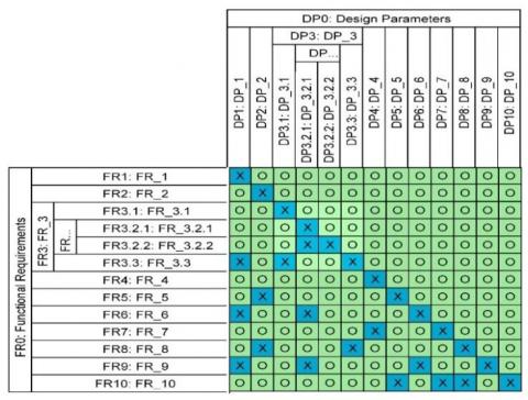
To finish the design process, the decomposition process of the highest-layer of {FRs} and corresponding {DPs} must proceed to obtain the detailed design. This process must continue level-by-level until the design arrives at the leaf level.
The D&Z process starts by zig from the functional domain (FD) to PD to find the corresponding {DPs} that fulfills the {FRs}. Then, zag to FD to obtain the functions that the developed {DP} must execute to achieve the above {FR} and fulfill the allocated {ICs}. Accordingly, new {DPs} will be found to the newly created {FRs}. Through each level of D&Z process, ensure that the proposed design achieves the first axiom as presented in Figure 14. Moreover, analyze {ICs} again at all levels to ensure that the suggested solution accomplishes the {ICs}. Through the D&Z process, the {FRs} and {DPs} hierarchies will be established as shown in Figure 15. During the D&Z process, there may be several {DPs} for each {FR}. It is necessary to compare and discuss these solutions to select the best one using the second axiom.
Figure 14. D&Z of the FR-DP mapping
Figure 15. FR-DP Tree diagram
5.3 Develop activity-based DSM from the design matrix
The development processes of a large system such as cars, aircraft, or satellites require the work of more than a hundred to thousands of people over the period of numerous months to numerous years. Usually, these large systems encompass thousands of components that have to be designed, autonomous tested, assembled, and then tested to check the accomplishment of {SNs}. In this picture, two large and complex groups have appeared as follows:
(1) The components and the parts group that interacts to form the system.
(2) The people group that interrelates to design and develop the system.
Understanding these two groups are decisive for managing and controlling all processes of development. To manage these two groups for delivering high-quality system faster and cheaper the next points have to be addressed:
(1) Interrelations or dependencies among people activities must be captured and understood. It is better to capture these interrelations at the early stage of SDL.
(2) Interactions between SCs must be captured (will be presented in Section 5.5).
For the first point, there are two methods to get the DSM during the development process as follows [13]:
(1) The traditional method, it based on developing the DSM by holding interviews with the managers and designers of the system as well as through reading the design documentation. In the case of incremental design, this method works well because it relies on the experience of designers and managers and the existence of design documentation. While in the case of creative (newly) design this method is not applicable mainly at the early phase because it is not reasonable to develop DSM for the new system that has never been designed before.
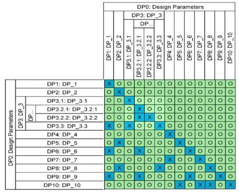
(2) Transform design matrix (DM) to DSM, Dong and Whitney proposed this technique to develop the DSM at the early phase of creative design where the gravest decisions about the system are made [14]. In this method, the creation of the DSM is applicable because DM has been created in the early phase of system design. Generally, the activities can often be offered as sets of design parameters that the transdisciplinary team actually work to be determined [15-16]. Consequently, the DSM that developed based on this method is the activity-based DSM that capture the interrelation among design activities.
In this study, the second method has been used to develop the activity-based DSM as shown in Figure 16.
Figure 16. Activity-based DSM
Figure 16 shows that the DSM was created depending on the leaf level of {DPs} because this level represents the DPs that the transdisciplinary team actually work to be determined.
5.4 Design components and supplier identities
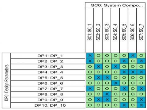
The system synthesis is started directly once the {DPs} specified. For each {DP}, the physical entity{SCs} is identified to fulfill the solution stated in the {DPs}. The linkage from {DPs} to {SC}s may be one or multiple-to-one linkage based on the level of decomposition (system, subsystem, …, component specification) as shown in Figure 17.
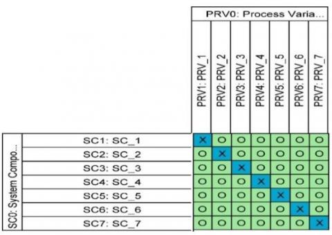
For each {SC}, the {PRV} will be identified to represent the process to produce the {SC} as depicted in Figure 18. These processes may be manufacturing, purchasing, assembling, or coding. The {PRV} type depends on the depth of decomposition of {SCs}. For example, in the system level, the {PRV} will be assembly process to integrate the subsystems together to form the system.
Once {SCs} and {PRVs} are determined, the list of available suppliers is recorded to the surety that the proposed {SC} is obtainable. This process will cover the supply dimension in SDD. In the case of the incremental design, the suppliers sheet already exist and will be updated only depending on the new added {SCs}. In the case of the new design, the sheet will be created from scratch.
Figure 17. [SS] matrix
Figure 18. [P] matrix
The most selected and effective suppliers are those who provide components that coincide or exceed the developer needs. There are characteristics must be available in the suppliers to be chosen and registered in the suppliers’ list. These characteristics vary according to the type and criticality of the final product\system. For example, in the space industry, the selection criteria are mentioned in the quality assurance plan (QAP) document that is developed in the preliminary requirement review phase (PRR) and updated through the next phases of the project lifecycle [17].
After the selection process is completed, the outputs will be documented in a supplier’s list as shown in Table 3. This list contains at least a supplier email, supplier location, communication method, and the staff assigned to interview with the supplier to discuss the request for proposal (RFP) document.
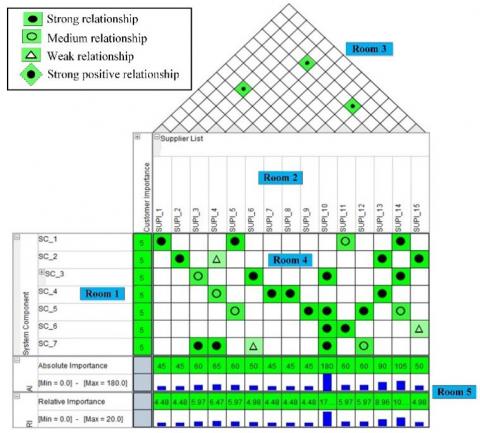
To manage and visualize the linkage between each {SC} and {SUPIs}, the QFD tool will be used as presented in Figure 19. One of the main benefits of QFD is its ability to take many forms depending on the problem type that will be solved [18].
Table 3. Supplier sheet
|
Supplier No |
[SUPI] Supplier Name |
[SUPI] Supplier Location |
[SUPI] Communication Method |
[SUPI] Staff assigned to do interview |
[SUPI] Review |
|
SUPI_1 |
|||||
|
.... |
|||||
|
SUPI_15 |
Figure 19. QFD-4 Mapping from SCs to SUPIs
As usual, the data that has been gathered and organized in QFD-4 must be analyzed.
(1) In room 4, make sure there are no empty rows. Empty rows indicate a deficiency in finding suppliers that can supply these {SCs}. Therefore, we have to either change the solution or conduct a deeper search to find an appropriate supplier. If the decision to change this component is taken, the other components that will be affected by this change must be considered. Moreover, the cells in room 4 visualize the linkage between each {SC} and each {SUPI}. As depicted in Figure 19 the cells will be filled with the scale from 9 to 1. Scale 9 represents strong relationship (black circle) which indicates that this supplier has introduced this product many times and proved its quality and efficiency at work (or any other characteristics assigned by designers to judge on the capability of the supplier). Scale 3 represents a moderate relationship (white circle) which indicates that this supplier has introduced this product but with different specification and needs some modification. Finally, Scale 1 represents a weak relationship (white triangle) which indicates that this supplier has never provided this product previously but have the ability to produce it.
(2) From room 5, the absolute and relative importance of each supplier will help to determine which supplier can deliver more than one {SC}. Therefore, the choice of this supplier will facilitate the supplier management process and perhaps more cost-effective.
(3) Room 3 represents the suppliers that have business cooperation and mutual dependence. This process helps the developers to coordinate its purchasing and production and create an integrated plan for the supply chain.
In the case of existence many suppliers that have the capability to deliver the same SC, analytical hierarchy process (AHP) is conducted to pick out the best one. Quality, time, and cost are examples of attributes that help the developer to categorize the suppliers.
5.5 Component and system verification
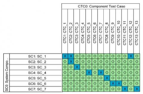
Once {SCs} are determined, a corresponding test that verify the components are identified and recorded in the Component Test Case vector {CTC}. These tests are standalone tests that are conducted before the beginning of system assembly, taking into consideration:
(1) SCs category.
(2) Availability of test tools.
(3) Schedule and cost.
{SCs} are categorized into four groups depending on the heritage of each component [19]. According to the {SCs} category, the test scope will be set for each of them as shown in Figure 20.
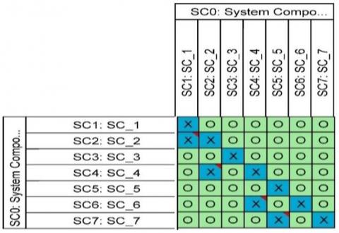
During the {SCs} testing, if failure happens, it is possible to know the top layers of {SCs} that will be affected due to this failure through the SCs hierarchy. However, these {SCs} are not all the {SCs} that affected by this failure because the SCs hierarchy represents functional interaction only, while the {SCs} interact with each other physically as well as functionally. Spatial, energy, information, and material are the interaction types between {SCs}[20]. Therefore, the component-based DSM will be developed to represent the physical interactions as shown in Figure 21.
Finally, the Functional Test Case vectors {FTC} must be specified to fully verify the top layer of {FRs} as shown in Figure 22. When the final system is assembled, the {FTC} will be conducted to execute the system acceptance test. Through the implementation of the final acceptance tests, {CTQs} will be checked to assess the degree of stakeholders’ satisfaction and to assure the developed system fulfills {SNs}.
Figure 20. [CT] matrix
Figure 21. Component-based DSM
Figure 22. [FT] matrix
As said before in Section 5, SEM will be responsible for facilitating all challenges facing the transdisciplinary team. The main challenges facing the transdisciplinary team during the SDL are [9]:
(1) Learn and enhance faster than competitors.
(2) Environment.
(3) Activities interrelation.
These challenges are enhanced by using the TQSDL methodology. The usage of QFD during the development process helped overcome the first challenge. As described in Section 5.2.1, room 6 represent the organization's strength and weakness on all sides of the system and in comparison, with its competitors. This room is essential if the organization wants to improve its competitiveness in the relevant market.
An environment is the surrounds, conditions, factors, or external objects that effect the implementation of the MBSE methodologies during the SDL [21]. To guarantee the best achievement of SDL processes, the suitable organizational environment has to be formed and an effective management structure takes place. In this study, we propose to use the TQSDL methodology in the Concurrent Design Environments (CDE) to overcome the second challenge. It has been confirmed through the previous decade that CDE [22]:
(1) Improve communication between the transdisciplinary team.
(2) Facilitate coordination of processes between different disciplines.
(3) Minimize cost and time of development.
(4) Increase the possibility of studying all potential technical solutions and exploring different architectures to find the most appropriate architecture.
(5) Satisfy the {SNs} because all stakeholders already participate during the design phase.
Concurrent design facility (CDF) is a particular facility with the goal of creating engineering designs. The main components for any CDF are [22]:
(1) Process.
(2) Team.
(3) Design model.
(4) Facility.
(5) Infrastructure.
SEM will use a TQSDL methodology to coordinate and manage the SDL process in the CDF. This CDF will be equipped with workstations that have an Accelaro software package as a modelling language. A single methodology that integrates all the design efforts like TQSDL methodology allows the transdisciplinary team to reduce the design time and cost.
Regarding the third challenge, the integration of DSM into the TQSDL process helped to overcome the activities interrrelation challenge.
In the present study, a novel MBSE methodology was presented, which was based on the TQSDL model combined with QFD and DSM tools. The previously established MBSE methodologies provide a good structure that supports the development of the large complex systems, however, they do not cover the whole SDD and development activities. The TQSDL methodology that is offered in this study has been able to overcome this problem and already covered all SDD. Moreover, two new theorems are issued to complement the theorems of AD, TSDL, and TQSDL model.
There are many processes missing in the established methodologies that often lead to weakness in technical management process through the SDL and hence will effect on achieving the roles of SEM. The TQSDL methodology offered an easy way to pursue the SDL process. This process presented in the Vee-shape as usual in the standard SE process. This Vee-shape guides and directs the transdisciplinary team to develop a complex system throughout the whole SDL.
The TQSDL methodology process is based on the integration between the TQSDL characteristic vectors, QFD, and DSM. These tools individually have presented massive concern in the engineering field. Consequently, the TQSDL process gained additional strength by integrating these tools to address the missing processes that were appeared in the previously established MBSE.
The TQSDL process succeeded in helping the SEMs to perform all their required roles through the whole SDL. Moreover, it helps the transdisciplinary team to track the interrelation between the development activities in bidirectional by using the design equations and following the sequence of development as presented in Vee shape.
By combining the QFD into the TQSDL methodology, the following benefits are obtained:
(1) Facilitates the prioritization of stakeholders.
(2) A better understanding of the SNs.
(3) Fewer problems mainly in the startup of the project.
(4) A competitive assessment of our system in the market.
(5)Support the process of trade-off analysis.
(6)Better management for the suppliers of SCs.
Similarly, by combining the DSM in the TQSDL methodology the following benefits are obtained:
(1) Capture the physical interactions between SCs.
(2) Obtain the activity interrelation in the primary phase of the development process when the most important decisions about the system are made.
(3) Improve process management.
(4) Improve information management.
(5) Support the process of estimating the changes in the development cost and hence will help the decision maker on whether or not to implement these changes.
Regarding the recommendation for future work, the current study suggests to add the SuD to cover and focus on one of the three sub-networks (supply sub-network) represented in the supply chain. It is recommended to connect the remaining sub-networks and modeling the supply chain process using an appropriate tool that includes the system behavior.
|
[A] |
Design matrix |
|
[C] |
Constraint matrix |
|
[CA] |
Constraint allocation matrix |
|
[CT] |
Component test matrix |
|
{CTC} |
Component test case vector |
|
{CTQ} |
Critical to quality vector |
|
{DP} |
Design parameters vector |
|
{DPC} |
Design parameters cost vector |
|
{FR} |
Functional requirement vector |
|
[FT] |
Functional test matrix |
|
{FTC} |
Functional teat case vector |
|
{IC} |
Input constraints vector |
|
[N] |
Need matrix |
|
[P] |
Process matrix |
|
{PRV} |
Process variable Vector |
|
[Q] |
Quality matrix |
|
[SA] |
Stakeholder allocation matrix |
|
{SC} |
System components vector |
|
{SCC} |
System components cost |
|
[SCA] |
System components allocation matrix |
|
{SI} |
Stakeholder identification vector |
|
{SN} |
Stakeholder need vector |
|
[SS] |
System structure matrix |
[1] INCOSE. (2015). Systems Engineering Handbook. A Guide for System Lifecycle and Activities, Fourth Edi. John Wiley & Sons.
[2] Friedenthal, S., Moore, A., Steiner, R. (2015). A Practical Guide To SysML: The Systems Modeling Language, Third edit. Elsevier Inc. http://doi.org/10.1016 /B978-0-12-800202-5.00001-1
[3] Estefan, J.A. (2008). Survey of Model-Based Systems Engineering ( MBSE ) methodologies. Technical Report, INCOSE MBSE Focus Group.
[4] Abdelrazek, M.A., El-sheikh, A.T., Zayan, M., Elhady, A.M. (2017). Systems engineering management using transdisciplinary quality system development lifecycle model. Int. J. Mech. Aerospace, Ind. Mechatron. Manuf. Eng., 10(2016).
[5] Sahlin, M. (2002). A decision framework for integrated synchronized development of high tech product. Proc. ICAD2002 Second Int. Conf. Axiomat. Des. Cambridge, pp. 1-7.
[6] Sage, A.P., Rouse, W.B. (2009). Handbook of Systems Engineering and Management, Second. John Wiley & Sons.
[7] Suh, N.P. (2001). Axiomatic Design: Advances and Applications. Oxford University Press.
[8] Gumus, B., Ertas, A., Tate, D., Cicek, I. (2008). The transdisciplinary product development lifecycle model. Journal of Engineering Design, 19(3): 185-200. http://doi.org/10.1080/09544820701232436
[9] El-Haik, B., Roy, D.M. (2005). Service design for six sigma: A road map for excellence. Wiley & Sons, Inc., Hoboken, New Jersey.
[10] Sheard, S. (1996). Twelve systems engineering roles. INCOSE 6th Annu. Symp., 703: 1-8. https://doi.org/10.1002/j.2334-5837.1996.tb02042.x
[11] Weiss, S.I. (2013). Product and systems development: A value approach. John Wiley & Sons.
[12] Bryson, J.M. (2004). What to do when Stakeholders matter - Stakeholder identification and analysis techniques. Public Manag. Rev., 6(1): 21-53. https://doi.org/10.1080/14719030410001675722
[13] Tang, D., Yin, L., Ullah, I. (2018). Matrix-based Product Design and Change Management. Springer. https://doi.org/10.1007/978-981-10-5077-0
[14] Dong, Q., Whitney, D.E. (2001). Designing a requirement driven product development process. Proc. DETC 2001 ASME 2001 Int. Des. Eng. Tech. Conf.
[15] Braha, D. (2002). Partitioning tasks to product development teams. Vol. 4 14th Int. Conf. Des. Theory Methodol. Integr. Syst. Des. Eng. Des. Cult. https://doi.org/10.1115/DETC2002/ DTM-34031
[16] Eppinger, S.D., Whitney, D.E., Smith, R.P., Gebala, D.A. (1994). A model-based method for organizing tasks in product development. Research in Engineering Design, 6(1): 1-13. https://doi.org/10.1007/BF01588087
[17] E. C. for S. Standardization. (2018). Quality Assurance.
[18] Prasad, K., Chakraborty, S. (2013). A quality function deployment-based model for materials selection. Mater. Des., 49: 525-535. http://doi.org/10.1016/j.matdes.2013.01.035
[19] E. C. for S. Standardization. (2018). Verification.
[20] Yassine, A. (2004). An Introduction to Modeling and Analyzing Complex Product Development Processes Using the Design Structure Matrix ( DSM ) Method. Urbana.
[21] Marchlewitz, S., Nicklas, J., Winzer, P. (2015). Using systems engineering for improving autonomous robot performance. in System of Systems Engineering Conference (SoSE), 2015 10th, IEEE. http://dx.doi.org/10.1109/SYSOSE.2015.7151947
[22] Bandecchi, M., Melton, B., Gardini, B., Ongaro, F. (2000). The ESA / ESTEC concurrent design facility. EuSEC 2000.