Hassina Abdellaoui* | Kaci Ghedamsi | Amar Mecharek
OPEN ACCESS
The objective of this study is to enhance the PEM fuel cell performances and increase its lifetime by using a Neutral-Point Clamped (NPC) seven-level inverter without any additional device in Hybrid Electric Vehicle (HEV) application. The multilevel inverter is used to feed a traction motor, which is in our system a permanent magnet synchronous machine (PMSM) of a hybrid electric vehicle. The energy management of the hybrid source (Fuel cell/ultracapacitor) using fuzzy logic is given and the vehicle speed is controlled by using the sliding mode control. The simulation results are compared to the conventional two-level inverter. Through this study,it was found that the use of seven-level inverter improve the power quality of traction motor,decrease the value of current and voltage THD (total harmonic distortion), reduce the constraint of the fuel cell, improve its efficiency and ensure length lifetime of hybrid electric vehicle (HEV) system. The main contribution of this paper is to show the advantages of using a seven-level inverter to increase the performance and lifetime of fuel cell in HEV application.
PMSM, ultracapacitor, multilevel inverter, sliding mode control, fuzzy logic control
With climate change becoming of increasing concern in recent years, vast global efforts have focused on producing renewable energy sources and reducing greenhouse gas emissions [1]. An interesting solution to produce near zero local emission electricity in an embedded system (as hybrid vehicle) is the fuel cell system [2]. The fuel cell technology is one representation of numerous clean energy technologies, because it possesses many advantages such as no pollution, high energy density, light weight, easy manufacturing, safety and so on, there is a trend for more and more research focusing on the development of fuel cell technology [3-4]. Therefore, the recent traction drive system of HEV consists of a FC stack, an ultracapacitor, power electronic circuit, and a traction motor. The hybrid input power is used to drive the electric motor associated with the vehicle dynamics and the resources of power electronics are used at various junctures for optimal energy management of the HEV. Fluctuating loads consist an important part of the power consumed in many applications. For automotive applications, they generate peaks reaching approximately more than ten times the power average pmoy of the load, which generates a very restrictive dynamic. For this, multilevel inverters can be employed in the HEV to feed the traction motor. It is an effective and practical solution for increasing power demand quality and reducing harmonics of ac waveforms [5-6]. As the number of levels increases, the synthesized output waveform has more steps, which produces a staircase wave that approaches in a desired waveform [7].
Many configurations or topologies of power converters are proposed whose objective is to find the ideal structure for an application type electrical vehicle (EV) [8-9]. The NPC inverter has been most widely used for application in high-power high-voltage (or medium-voltage) drives nowadays, because the imposed voltage across each switching power devices is half fraction of the conventional two-level inverter with the same ratings of the device [10].
Currently, many authors interest on the use of multilevel inverters for HEV. In [7], the IGBT based cascaded multilevel has been developed and it is interface with 20 kW 3-phase induction motors that proved to be suitable for HEVs. The references [5-11] propose the use of different level cascaded inverters to feed the traction motor in electric drive. It is found that the cascaded multilevel inverters are proper for medium-voltage high-power application; they reduce harmonics and produce sinusoidal voltages. However, based on their configurations, they are limited by the need of separate DC sources and they are more complicated than other types of converters. Therefore, in diode-clamped converters, there is simplicity in extending the voltage to higher levels. In addition, diode clamped converters are widely used in medium and low-power applications [12]. A Scott transformer topology is presented [13] to provide redundancy to the power switches in an Integrated Power Module (IPM) and a fault-tolerant scheme is simulated to test the operation of a permanent-magnet synchronous machine in a plug-in hybrid electric vehicle (PHEV).
In this paper, a NPC seven-level inverter is used to feed traction motor (PMSM). This multilevel inverter allow to get a best power quality with lower value of THD (total harmonic distortion) and able to sustain the operating performance of the speed of HEV in fault-tolerant mode. The energy management with fuzzy logic is given. The simulation results are compared to the conventional two-level inverter.
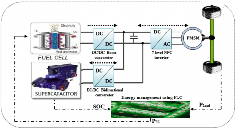
The global system is detailed in Figure 1. It is composed of two sources, the first one is the FC and the second one is the UC that are connected to the DC link bus through a unidirectional DC/DC and current bidirectional DC/DC converters respectively. The FC/UC currents are controlled using PI regulator and the DC link voltage is chosen to be maintained to 500V to supply the traction motor (PMSM) with employing of a seven-level inverter to convert the DC voltage on AC voltage. The energy management of hybrid source based on fuzzy logic is used in the whole vehicle cycle. Simulations are carried out using MATLAB/Simulink environment under various operating conditions to show the effectiveness of proposed methodology. Simulation results reflect the effectiveness of proposed scheme in steady state and dynamic operating conditions.
Figure 1. FC/UC hybrid electric vehicle topology
2.1 PEMFC modeling
The polymer electrolyte membrane fuel cell (PEMFC) is the main energy source for the vehicle. Its cell voltage and its total power are defined by the following equations [14-15]:
${{V}_{FC}}={{E}_{nernst}}+{{U}_{act}}-{{U}_{ohm}}-{{U}_{con}}$ (1)
${{U}_{ohm}}=\frac{{{I}_{FC}}}{A}\left[ \frac{181.5[1+0.03(\frac{{{I}_{FC}}}{A})+0.6\frac{T}{303}{{(\frac{{{I}_{FC}}}{A})}^{2.5}}]}{[\lambda -0.0633-3(\frac{{{I}_{FC}}}{A})]\exp [4.1(1-\frac{303}{T})]}{{I}_{FC}}+{{A}^{{}}}{{R}_{C}} \right]$ (2)
${{U}_{act}}=-\left[ {{\xi }_{1}}+{{\xi }_{2}}T+{{\xi }_{3}}T\ln \left( {{C}_{o2}} \right)+{{\xi }_{4}}T\ln \left( {{I}_{FC}} \right) \right]$ (3)
${{U}_{cond}}=-{{B}_{FC}}\ln \left( 1-\frac{{{I}_{FC}}}{{{I}_{FC,\max }}} \right)$ (4)
The expression of the Nernst equation is given as [16]:
$\begin{align} & {{E}_{Nernest}}=1.229-0.85\times {{10}^{-3}}(T-298.15)+4.3085\times {{10}^{-5}}T\left( \ln \left( {{P}_{H2}} \right)+0.5\ln \left( {{P}_{o2}} \right) \right) \\\end{align}$ (5)
The parameters of the FC are given in Table 1.
Table 1. Parameters of fuel cell
|
|
Symbol |
Values |
|
Nominal power |
PFC,nom |
35 kW |
|
Internal resistance |
RFC |
3 mΩ |
|
Activation over voltage constant |
B |
0.0477 V |
|
Hydrogen valve constant |
KH2 |
4.22.105k.mol.atm/s |
|
Temperature |
T |
65⁰C |
2.2 UC system modeling
The UltraCapacitor (UC) is used as an auxiliary power source. It is dedicated for applications where both energy and power density are needed. Even if their energy density is ten times lower than the energy density of batteries, Ultracapacitors have a long life virtually unlimited cycle life, they offer low resistance thus enables high load currents, offer rapid charging without the danger of overcharging and they are safe to use. A circuit model topology is selected, as shown in Figure 2.
Figure 2. Equivalent circuit of ultracapacitor
It is composed of a capacitance CCell, a series resistance rscorresponding to the charge and discharge resistance, a parallel resistance rp consisting of the self-discharge losses.
The modeling of the UC units is detailed by the following equations [17]:
${{V}_{Cell}}={{r}_{s}}{{i}_{Cell}}+\frac{1}{{{C}_{Cell}}}\int{\left( {{i}_{Cell}}-\frac{{{V}_{Cell}}}{{{r}_{p}}} \right)}$ (6)
${{V}_{UC}}={{\eta }_{UC}}{{V}_{Cell}}$ (7)
The parameters of the UC are given in Table 2.
Table 2. parameters of ultracapacitor
|
|
Symbol |
Values |
|
Capacity |
F |
500 F |
|
Resistance |
RUC |
2.4 mΩ |
|
Voltage |
VUC |
16.2 V |
|
Maximal power |
PUCmax |
40 kW |
2.3 PMSM modeling
Permanent-magnet synchronous machines are gradually considered the better choice of traction motors of HEV, due to their high power density and high efficiency. Modeling of a PMSM without damper winding has been developed using the following assumptions [18]: Saturation is neglected; the induced EMF is sinusoidal; Eddy currents and hysteresis losses are negligible; there are no field current dynamics.
Voltage equations are given by [19-20]:
$\left\{ \begin{align} & {{v}_{ds}}={{R}_{s}}{{i}_{ds}}+\frac{d}{dt}{{\varphi }_{ds}}-\omega {{\varphi }_{qs}} \\ & {{v}_{qs}}={{R}_{s}}{{i}_{qs}}+\frac{d}{dt}{{\varphi }_{qs}}-\omega {{\varphi }_{ds}} \\\end{align} \right.$ (8)
The mechanical equation of the synchronous machine can be written:
${{J}_{m}}\frac{d\Omega }{dt}={{C}_{em}}-{{C}_{r}}-f\Omega $ (9)
where, the electromagnetic torque can be expressed by:
${{C}_{em}}=\frac{3}{2}P\left( {{\varphi }_{d}}{{i}_{q}}-{{\varphi }_{q}}{{i}_{d}} \right)$ (10)
uch as: $\omega =P\Omega $ and $\Omega =\frac{d}{dt}\theta $
Flow-current relations are given by:
$\left\{ \begin{align} & {{\Phi }_{ds}}={{L}_{ds}}{{i}_{ds}}+{{\Phi }_{f}} \\ & {{\Phi }_{qs}}={{L}_{qs}}{{i}_{qs}} \\\end{align} \right.$ (11)
2.4 Seven-level NPC inverter modeling
A three-phase seven-level NPC inverter is shown in Figure 3.
Figure 3. Three-phase 7-level NPC inverter circuit topology
The DC bus consists of six capacitors, C1, C2, C3, C4, C5 and C6. For DC-bus voltage Vdc, the voltage across each capacitor is Vdc/6, and each device voltage stress will be limited to one capacitor voltage level Vdc/6 through clamping diodes.
To explain how the staircase voltage is synthesized, the neutral point n is considered as the output phase voltage reference point [21]. There are seven switch combinations to synthesize seven level voltages across (a, b, c) and n is given in Table 3.
Table 3. Switching states for a seven level NPC inverter
|
V0 |
Vdc/2 |
Vdc/3 |
Vdc/6 |
0 |
Vdc/6 |
Vdc/3 |
Vdc/2 |
|
S1 |
1 |
0 |
0 |
0 |
0 |
0 |
0 |
|
S2 |
1 |
1 |
0 |
0 |
0 |
0 |
0 |
|
S3 |
1 |
1 |
1 |
0 |
0 |
0 |
0 |
|
S4 |
1 |
1 |
1 |
1 |
0 |
0 |
0 |
|
S5 |
1 |
1 |
1 |
1 |
1 |
0 |
0 |
|
S6 |
1 |
1 |
1 |
1 |
1 |
1 |
0 |
|
S7 |
0 |
1 |
1 |
1 |
1 |
1 |
1 |
|
S8 |
0 |
0 |
1 |
1 |
1 |
1 |
1 |
|
S9 |
0 |
0 |
0 |
1 |
1 |
1 |
1 |
|
S10 |
0 |
0 |
0 |
0 |
1 |
1 |
1 |
|
S11 |
0 |
0 |
0 |
0 |
0 |
1 |
1 |
|
S12 |
0 |
0 |
0 |
0 |
0 |
0 |
1 |
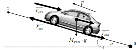
As shown in Figure 4, the vehicle is considered as a solid point moving subjected to forces along the longitudinal axis: the traction forces Ft caused by the action of the two drive wheels, the friction force to the advancement Froll, the effort of aerodynamic resistance Faero and the resistance of mounted side Fslope [22-23].
Figure 4. Dynamics of the vehicle
${{F}_{aero}}=\frac{1}{2}\rho A{{C}_{X}}V_{v}^{2}$ (12)
${{F}_{slope}}={{M}_{v}}g\sin \left( \delta \right)$ (13)
The fundamental principle of the vehicle dynamics is described by the following equation:
${{M}_{v}}\frac{d{{v}_{v}}}{dt}={{F}_{t}}-{{F}_{roll}}-{{F}_{aero}}-{{F}_{slope}}$ (14)
The traction force of each wheel is given by the following expression:
$\frac{{{F}_{t}}}{2}=\frac{T}{{{R}_{\omega }}}$ (15)
The parameters of the HEV model are given in Table 4.
Table 4. Vehicle parameters
|
|
Symbol |
Values |
|
Vehicle total mass |
Mv |
800 kg |
|
Frontal surface area of the vehicle |
Af |
1.75 m2 |
|
Rolling resistance coefficient |
Cr |
0.009 |
|
Air density |
ρair |
1.2 kg/m3 |
|
Acceleration due to gravity |
g |
9.81 m/s2 |
The current regulation of DC/DC converters and bus voltage control using PI regulator are presented in this section. The energy management strategy using fuzzy logic is given. The traction motor is fed by seven level inverter to optimize the power required by a hybrid sources. The speed of vehicle is controlled using sliding mode control.
3.1 Speed regulation and inverter control of PMSM
PMSMs nowadays are commonly used in industrial applications in the field of motion control. Major reasons for their popularity are high power density and high efficiency [12]. But, PMSM is multivariable, non-linear, strongly coupled, and very sensitive to outside disturb and parameter variation, which makes it difficult for applied conventional linear control technologies to get perfect control performance of PMSM [24-25]. Rapidly developing robust control theory provides an ideal solution for this problem. Sliding Mode Control (SMC) is a special robust control method, which can self-adjust controller structure online and be non-sensitive to parameter variation and outside disturb. SMC is so fit for solving control problems of non-linear uncertain system [26].
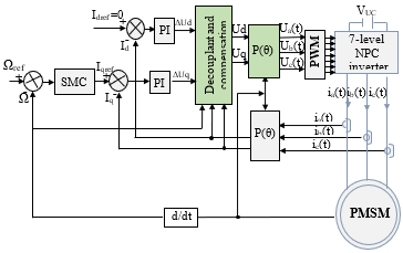
The Figure 5 shows the vector control of the PMSM.
Figure 5. Vector control of PMSM
Using the sliding mode control, the objective is to force the system dynamics to match the sliding surface S(x) by the following equation command:
$U={{U}_{eq}}+{{U}_{n}}$ (16)
With: U - control variable ${{U}_{eq}}$ - size equivalent command,
${{U}_{n}}$- size discontinuous control.
${{U}_{n}}={{K}^{{}}}sig{{n}^{{}}}\left( S\left( x \right) \right)$ (17)
With: K is a positive gain
So that the surface is attractive, the regulator sliding mode should be selected so that the function satisfies the criterion of Lyapunov stability [27-28]:
$S{{\left( x \right)}^{{}}}\dot{S}\left( x \right)\le 0$ (18)
The sliding surface is defined by:
$S\left( \Omega \right)={{\Omega }_{ref}}-\Omega $ (19)
The derivative of this surface is given by the following expression:
$\dot{S}\left( \Omega \right)=-{{C}_{1}}\Omega +\frac{{{C}_{r}}}{J}+{{\Omega }_{ref}}-\left( {{C}_{2}}{{I}_{ds}}+{{C}_{3}} \right){{I}_{qs}}$ (20)
3.2 UC converter control and DC bus voltage regulation
3.2.1 DC bus voltage control
The bidirectional buck-boost converter is a component key for the hybridization. It is an electrical device that transforms unregulated DC power to regulated DC bus power in the hybrid configuration. We should control PWM of T12 and T22 to make voltage of DC stable and limit the UC current. The control strategy of bidirectional converter is shown in Figure 6.
Figure 6. DC bus voltage regulation and the UC converter control
3.2.2 FC converter control
Figure 7 shows a boost DC/DC converter with fuel cell current regulation. The FC power reference is divided by the FC voltage to obtain the reference value. The FC current is measured and compared with a reference value, and the error signal is processed through the PWM (pulse with modulation) controller, which is a simple proportional integral (PI) controller.
Figure 7. Fuel Cell converter control
In recent years, many studies have adopted intelligent techniques to perform energy management in hybrid systems. Principally, fuzzy logic as required for many applications [29]. Fuzzy systems are control methods that can be effectively and powerfully used for nonlinear systems in which deriving a mathematical model that represents the system operation is difficult [30-31]. The energy management strategy using fuzzy logic (Figure 8) coordinates all the elements in the system to provide continuously the necessary traction, to keep constant the DC bus voltage (Vbus) and maintain the UC SOC (state-of-charge).
Figure 8. Energy management using fuzzy logic
The inputs of FLC (Fuzzy logic control) are: The load power (Pload) and ultracapacitor SOC, and the output of FLC is the fuel cell power (PFC).
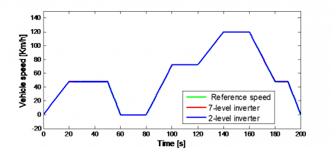
To validate the proposed work, simulation studies have been curried by using MATLAB/SIMULINK. The results have been done using an aleatory drive cycle of 200 seconds and with 120 km/h maximum speed as shown in Figure 9.
Figure 9. Speed vehicle during the proposed cycle
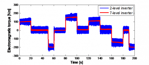
(a) Traction motor power
(b) Electromagnetic torque
Figure 10. Traction motor power and electromagnetic torque
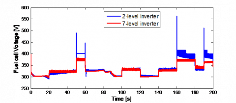
(a) Fuel cell voltage
(b) Fuel cell current
(c) Fuel cell power
Figure 11. Fuel cell voltage, fuel cell current and fuel cell power
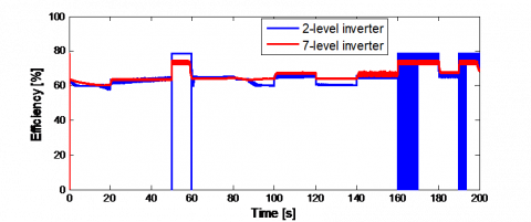
Figure 12. Fuel cell efficiency [%]
Table 5. Comparison of voltage THD and current THD between the two inverter configurations
|
Inverter configuration |
THD (%) |
|
|
Voltage |
current |
|
|
Two-level inverter |
69.87 % |
30.25 % |
|
Seven-level inverter |
20.09 % |
16.7 % |
The speed of the vehicle follows the reference speed as shown in Figure 9, but with the use of a multilevel inverter, the speed is smoother compared to that obtained with the two-level inverter.
Figure 10 shows the power and the electromagnetic torque of PMSM. It seen that the electrical and mechanical performance of traction motor are significantly improved using 7-level inverter. Current and voltage THD (Table 5) are greatly decreased with the multilevel inverter.
The electric parameters of fuel cell are shown in Figure 11, we can remark from these results that the load fluctuations are eliminated in the case of using a multilevel inverter. The quality of the power is improved and the efficiency of the fuel cell, as shown in Figure 12, is better.
Our main objective in this work was the improvement of the fuel cell performance. Since the characteristics of the fuel cell depend heavily on the load, multilevel inverter was the right solution to enhance the electrical and mechanical performance of the traction motor.
The different simulation results obtained, showed the interest of using a 7-level inverter in HEVs by enhancing the performance of the load, increasing the quality of the power, decreasing of the electromagnetic torque ripple and the reduction of the current and the voltage THD’s. This allowed reducing the load constraints on the fuel cell and improving its characteristics and performance. This has made it possible to get a better quality of the power of the ultracapacitor and also of the bus voltage.
Therefore, from this study, it can be concluded that the use of a multi-levels NPC inverter for HEV gives satisfactory results in terms of system performance, ensures continuity of service in the event of semiconductor failure and increase the lifetime of the vehicle.
|
VFC |
FC cell output voltage, V |
|
|
Enernest |
FC cell potential open-circuit voltage, V |
|
|
Uact |
Activation voltage drop, V |
|
|
Uohm |
Ohmic voltage drop, V |
|
|
Ucond |
Concentration voltage drop, V |
|
|
IFC |
Fuel cell current density, A.cm2 |
|
|
A |
Cell active area, cm2 |
|
|
Rc |
Equivalent resistance to proton conduction, Ω |
|
|
T |
Operation temperature, ℃ |
|
|
ξi |
parameters corresponding to Uact, |
|
|
BFC |
Empiric coefficient for the concentration losses |
|
|
PH2 |
Partial pressure of hydrogen, atm |
|
|
PO2 |
Partial pressure of oxygen, atm |
|
|
VCell |
UC cell voltage, V |
|
|
rs |
UC series resistance, Ω |
|
|
rp |
UC parallel resistance, Ω |
|
|
CCell |
UC cell capacitance, F |
|
|
UC cells number put in series |
|
|
VUC |
UC voltage, V |
|
|
Φqs |
Quadrature flux axis, Wb |
|
|
Ω |
Mechanical speed of the rotor, rpm |
|
|
ω |
Electrical speed of the rotor, rd/s |
|
|
Jm |
Moment of the inertia, kg·m2 |
|
|
Cem |
Electromagnetic torque of PMSM, N.m |
|
|
Cr |
Resistance torque, N.m |
|
|
f |
Viscous friction coefficient, N·m·s |
|
|
P |
Number of pole pairs |
|
|
Lds |
Direct stator inductance, H |
|
|
Lqs |
Quadrature stator inductance, H |
|
|
Φf |
Flux induced by magnet, Wb |
|
|
Ft |
Traction force caused by the action of the two drive wheels, N |
|
|
Froll |
Friction force to advancement, N |
|
|
Faero |
Effort of aerodynamic resistance, N |
|
|
Fslope |
Resistance force of mounted side, N |
|
|
Mv |
The vehicle weight, kg |
|
|
g |
The gravitational acceleration, 9,81 m/s2 |
|
|
fr |
The resistance coefficient of the tire rolling |
|
|
ρ |
The air density, N·m·s/rd |
|
|
Av |
Front area of the vehicle, m2 |
|
|
Cx |
Aerodynamic drag coefficient |
|
|
Vv |
The vehicle speed, m/s |
|
|
Tr |
The electromagnetic torque, N·m |
|
|
Rw |
The wheel radius, m |
[1] Larminie, J., Dicks, A. (2003). Fuel Cell Systems Explained (2nd edition). Wiley & Sons Ltd, Chichester, UK.
[2] Napoli, G., Micari, S., Dispenza, G., Di Novo, S., Antonucci, V., Andaloro, L. (2017). Development of a fuel cell hybrid electric powertrain: A real case study on a Minibus application. International Journal Hydrogen Energy, 42(46): 28034-28047. https://doi.org/10.1016/j.egypro.2017.12.645
[3] Ettihir, K., Higuita Cano, M, Boulon, L, Agbossou, K. (2017). Design of an adaptive EMS for fuel cell vehicles. International Journal of Hydrogen Energy, 42(2): 1481-1489. http://doi.org/10.1016/j.ijhydene.2016.07.211
[4] Wang, C.S., Nehrir, M.H. (2007). Load transient mitigation for standalone fuel cell power generation systems. IEEE Transactions on Energy Conversation, 22(4): 864-872. https://doi.org/10.1109/TEC.2006.881081
[5] Liu, J.X., Laghrouche S., Ahmed, F.S., Wack, M. (2014). PEM fuel cell air-feed system observer design for automotive applications: An adaptive numerical differentiation approach. International Journal of Hydrogen Energy, 39(30): 17210-17221. https://doi.org/10.1016/j.ijhydene.2014.08.013
[6] Bhavani, R., Swapna, G. (2016). Multilevel inverter for higher output voltage levels. International Journal for Research in Applied Science & Engineering Technology (IJRASET), 4(7): 506-515.
[7] Salodkar, P., Sandeep, N., Kulkarni, P.S., Yaragatti, U.R. (2014). A Comparison of seven-level inverter topologies for multilevel DC-AC power conversion. IEEE International Conference on Power Electronics, Drives and Energy Systems (PEDES), 4799-6373. https://doi.org/10.1109/PEDES.2014.7042043
[8] Verma, A.K., Thakura, P.R., Jana, K.C., Buja, G. (2011). Cascaded multilevel inverter for hybrid electric vehicles. India International Conference on Power Electronics (IICPE), 1-6. https://doi.org/10.1109/IICPE.2011.5728093
[9] Fatemeh, M., Abbas, K. (2014). A preliminary study for improving reliability in hybrid vehicles. Procedia Computer Science, 42: 308-312. https://doi.org/10.1016/j.procs.2014.11.067
[10] Barriuso, P., Dixon, J., Flores, P., Moran, L. (2009). Fault tolerant reconfiguration system asymmetric multilevel converters using bi-directional power switches. IEEE transactions on Industrial Electronics, 56(4): 1300-1306. https://doi.org/10.1109/TIE.2008.2005680
[11] Park, J.J., Kim, T.J., Hyun, D.S. (2008). Study of neutral point potential variation for three-level NPC inverter under fault condition. Industrial Electronics (IECON), 34th Annual Conference of IEEE, 983-988. https://doi.org/10.1109/IECON.2008.4758087
[12] Khoucha, F., Lagoun, M.s., Marouani, K., Kheloui, A., Benbouzid, M. (2008). Hybrid cascaded h-bridge multilevel inverter motor drive DTC control for electric vehicles. Proceedings of the International Conference on Electrical Machines, 55(2): 956-958 https://doi.org/10.1109/TIE.2007.896527
[13] Sangdehi, S.M.M., Hamidifar, S., Kar, N.C. (2014). A novel bidirectional DC/AC stacked matrix converter design for electrified. IEEE Transactions on Vehicular Technology, 63(7): 3038-3050. https://doi.org/10.1109/TVT.2014.2325740
[14] Dat, M.T., Cheng, Y.H., Driesen, J. (2012). Fault-tolerant operation of power converters in phevs coupled by a scott transformer. 38th Annual Conference of the IEEE Industrial Electronics Society (IECON), 4258-4263. https://doi.org/10.1109/IECON.2012.6389205
[15] Marzougui, H., Amari, M., Kadri, A., Bacha, F., Ghouili, J. (2017). Energy management of fuel cell/battery/ ultracapacitor in electrical hybrid vehicle. International Journal of Hydrogen Energy, 42(13): 8857-8869. https://doi.org/10.1016/j.ijhydene.2016.09.190
[16] Aouzellag, H., Ghedamsi, K., Aouzellag, D. (2015). Energy management and fault tolerant control strategies for fuel cell/ultra-capacitor hybrid electric vehicles to enhance autonomy, efficiency and life time of the fuel cell system. International Journal of Hydrogen Energy, 40(22): 7204-7213. https://doi.org/10.1016/j.ijhydene.2015.03.132
[17] Qingshau, X., Nianshin, W., Ishianagi, K., Yukita, K. (2008). PEM fuel cell modeling and parameter influences of performance evaluation. Third International Conference on Electric Utility Deregulation and Restructuring and Power Technologies, DRPT. https://doi.org/10.1109/DRPT.2008.4523891
[18] Amrouche, B., Otmane Cherif, T., Ghanes, M., Iffouzar, K. (2017). A passivity-based controller for coordination of converters in a fuel cell system used in hybrid electric vehicle propelled by two seven phase induction motor. International Journal of Hydrogen Energy, 42(42): 26362-26376. https://doi.org/10.1016/j.ijhydene.2017.08.099
[19] Shahat, H., El Shewy, H. (2010). PM Synchronous motor drive system for automotive applications. International Journal of Electrical systems, 6(2).
[20] Maiti, S., Chakraborty, C., Sengupta, S. (2009). Simulation studies on model reference adaptive controller based speed estimation technique for the vector controlled permanent magnet synchronous motor drive. International Journal of Simulation Modeling Practice and Theory, 17(4): 585-596. https://doi.org/10.1016/j.simpat.2008.08.017
[21] Huang, J., Li, H., Chen, Y., Xu, Q. (2012). Robust position control of PMSM Using fractional-order sliding mode controller. Hindawi Publishing Corporation Abstract and Applied Analysis. Article ID 512703. http://dx.doi.org/10.1155/2012/512703
[22] Sanoop, P., Vinita, Ch. (2016). Seven level inverter topologies: A comparative study. International Journal of Innovative Research in Electrical, Electronics, Instrumentation and Control Engineering (IJIREEICE), 3(1): 148-162.
[23] Payman, A., Pierfederici, S., Meibody-Tabar, F. (2008). Energy control of super capacitor/fuel cell hybrid power source. International Journal of Energy Conversion and Management, 49(6): 1637-1644. https://doi.org/10.1016/j.enconman.2007.11.012
[24] Hwang, J.J., Chen, Y.J., Kuo, J.K. (2012). The study on the power management system in a fuel cell hybrid vehicle. International Journal of Hydrogen Energy, 37(5): 4476-4489. https://doi.org/10.1016/j.ijhydene.2011.11.127
[25] Ji, M.H. (2007). Summarize and prospect of the PMSM system of frequency-conversion and timing. J Small and Special Electrical Machines, 3: 49-52.
[26] Bose, B.K. (2009). Power electronics and motor drives recent progress and perspective. IEEE Transactions on Industrial Electronics, 56(2): 581-588. https://doi.org/10.1109/TIE.2008.2002726
[27] Lin, W.J., Liu, D.L., Wu, Q.X., Zhao, X.D. (2014). On sliding mode control of permanent magnet synchronous motor. 26th Chinese Control and Decision Conference (CCDC). https://doi.org/10.1109/CCDC.2014.6852985
[28] Dhamo, L., Spahiu, A. (2013). An improved performance of sensorless PMSM drive control with sliding mode observer in low speed operation. Int J Engineering Trends and Technology (IJETT), 4(5): 2231-5381.
[29] Reichhartinger, M., Horn, M. (2010). Sliding-mode control of a permanent magnet synchronous motor with uncertainty estimation. International Journal of Electrical and Computer Engineering, 4(11): 1637-1640.
[30] Abadlia, I., Bahi, T., Bouzeria, H. (2016). Energy management strategy based on fuzzy logic for compound RES/ESS used in stand-alone application. International Journal of Hydrogen Energy, 41(38): 16705-16717. https://doi.org/10.1016/j.ijhydene.2016.07.120
[31] Olatomiwa, L., Mekhilef, S., Ismail, M.S., Moghavvemi, M. (2016). Energy management strategies in hybrid renewable energy systems: A review. Renew Sustain Energy, 62: 821-835. https://doi.org/10.1016/j.rser.2016.05.040