Simon Collart-Dutilleul*![]() | Philippe Bon | Racem Bougacha
| Philippe Bon | Racem Bougacha![]() | Régine Laleau
| Régine Laleau![]()
© 2023 IIETA. This article is published by IIETA and is licensed under the CC BY 4.0 license (http://creativecommons.org/licenses/by/4.0/).
OPEN ACCESS
Fulfilling norms is a way to respect all the safety properties embedded in norm specifications. Moreover, it provides interoperability qualities that are particularly relevant in the transport domain. The article proposes a modelling engineering approach using a semi-formal model phase to identify a multilayered decomposition of the system with domain experts. Then a transformation into formal models is used in order to verify and validate the behaviour with technical and safety experts. Propositions are illustrated on a case study from the transport domain: Automatic Train Operation (ATO) over European Train Control System (ETCS), also named AoE, for freight trains. ATO under the supervision of a human driver is sometimes presented as a first step toward autonomous train. This paper provides a system analysis of the available norms dealing with automatic train operation under driver supervision. The work focuses on the collaboration between an automatic software for braking and accelerating in the European normative and technological context, known as AoE. From the study of the available documents, we derive an architectural model of this global system containing on board automation and on track automated specific devices. The technical contribution is a proposition of an approach specifying a correct-by-construction software system. This software component respects the industrial norms of automated train. We explain how it is relevant to use a norm-based technical architecture, that allow drivers to identify various functioning phases where, depending on the overall context, they can let an automatic system drive the train or not.
model engineering, formal method, European Railway Train Management System (ERTMS), Automatic Train Operation (ATO), ATO over ETCS (AoE), Grade of Automation (GoA), autonomous freight train
An ISO standard is the result of a process ensuing from an international industrial consensus. The norm provides a specification, the quality of which is ensured by international experts and may detail the mean to ensure a correct implementation of a given standard. To provide an example in the railway domain, the behavioural specification for the European Vital Computer (EVC) is documented in Subset 26 [1], but the mean for checking this subset fulfilment can be found in Subset 76 [2]. This last subset provides a set of test scenarios that have to be performed successfully, whereas a test bench specification is available in Subset 94 [3]. The European Commission required that corresponding tests have to be executed by independent test laboratories and a way for these independent laboratories to validate their ability is to be evaluated by a national accreditation office in charge of the respect of the ISO/IEC 17025 (https://www.boutique.afnor.org/en-gb/standard/iso-iec-170252017/general-requirements-for-the-competence-oftesting-and-calibration-laborato/xs129227/127779) norm. The global framework for EVC assessment is industrially running for many years. It is also efficient, but expensive because of the use of test benches belonging to external laboratories. Moreover, when the technical system becomes more complex, the quantity of tests exceeds, in the case of Subset 26 conformance, the quantity of 800 tests that must be performed on the real EVC. Considering that there are no laboratories for independent EVC testing in Netherlands, it is obvious that additional constraints introduced in the industrial process are heavy and expensive. In this paper another approach, to assess conformity to norms, is proposed. It transforms a model specifying the required behaviour into a formalism that allows generating byte code or source code in such a way that a continuous certified workflow produces the software, ensuring the required properties.
Section 2 explains step by step the global model engineering methodology while discussing the potential added value of norm modelling, providing examples relative to the railway domain. In Section 3, the methodology is partly illustrated on a case study. This case study is documented using normative or pre-normative documents and the main objects are identified and exploited in order to provide a set of software entities that may be used to build software services. Section 4 provides some conclusions and prospects concerning the remaining unsolved methodological, technical and scientific deadlocks.
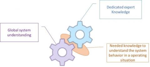
A model is essentially an abstraction of the real world. It means that some architectural and functioning details are not described, assuming that they are not relevant with regard to a given point of view of the analysis. As a consequence, a model provides an abstract oriented point of view that helps to understand a system in order to analyse it locally (Figure 1). Considering a railway system which is a complex socio-technical system, using models is relevant as various expert knowledge from many technical fields are involved, in such a way that it is really difficult to find a human able to tackle with all the concerned fields. Considering that for an industrial project, a consistent task force is needed in order to decrease delays, then it becomes obvious that model engineering can be a good solution as explained in the study [4].
Figure 1. Projection of various expert knowledge on a given operation at a given state
A challenging task in the modelling process is the correct understanding of the specification, that requires collaboration with system experts. As ambiguities pave the way to misunderstanding, a common modelling language is needed. Moreover, creating a structured knowledge is a human action that is error prone and time expensive. The use of libraries of well-defined object, if available, is of great added value, as the process becomes safer and faster. In the railway area, a common ontology of all actors of the railway system, named Ontorail (https://ontorail.org/wiki/), has been introduced by the International Union of railway (UIC). Nevertheless, it is not sufficient for scenario identification. In order to characterize a given situation in a professional railway context, the RailTopoModel (http://www.railtopomodel.org/) standard may be used. Finally, when a precise and rigorous description is needed, dynamic scenarios can be specified by using specific ontologies such as Goal-Oriented Requirements Ontology (GORO) [5]. Examples of using ontology engineering in order to model railway accidents can be found in the state of the art [6]. Once the main entities of the system have been identified and defined in a structured formalism, their interactions producing the system functions must be described by SysML (Systems Modeling Language) use case diagrams. Reader not familiar with SysML notations may refers to the study [7]. Figure 2 provides useful information about the case study, more precisely described in the following section. Before going into details, the considered system is the train. As a consequence, the behaviour of the track-side will not be described. Only interactions through interfaces are in the framework of this study. The resulting granularity of descriptions concerning on board and trackside systems will be non-homogeneous, but it is a result of the system definition provided by the corresponding use case diagrams. For railway systems, there is an industrial consensus for using SysML, a modeling language for systems engineering applications (https://www.iso.org/standard/65231.html). For example, RailtopoModel, released as International Railway Standard (IRS) 30100 in April 2016, and describing a railway infrastructure, is specified using SysML. For this reason, it is possible to find railway experts who understand SysML notations and diagrams.
Figure 2. Use case diagram of GoA2 over ETCS
Once a model of the system is built, it can be used for various analyses. For instance, in the case of model-based testing approach, test sequences can be generated from the model. These test sequences are used in conformance testing methodologies like in ISO/IEC 96466:1994 (https://webstore.iec.ch/publication/11879). In the state of the art, several works propose to use UML/SysML sequence diagrams and statecharts to build Petri Net models [8]. Indeed, Petri Net models are efficient to process to behavioural validation, performing simulations. Moreover, performance evaluation can be computed using timed or stochastic extensions of Petri Nets [9]. When a Petri Net model is validated, test sequences can be generated as in the study [10]. Another option is to derive an implementation from models of the system, previously validated by domain experts. Then a correct implementation of this model is assessed by the proof of a refinement process between the model of the system and the model of the norm. In this case, the model conformance is formally proved. To achieve this goal, SysML diagrams need to be transformed into formal notations allowing the use of refinement, such as the Event-B method [11, 12]. Let us point out that for a proved refinement, the implementation must be available in a readable format for experts in charge of the conformity assessment. This is not as flexible as black box testing, nevertheless black-box testing performed by an independent laboratory implies heavy industrial constraints. If the conformance is provided by a formal proof performed on a model of the candidate solution [13], the conformity assessment process looks more efficient. In fact, this kind of process is accepted by STRMTG (https://www.strmtg.developpement-durable.gouv.fr/), the French Technical service for ski lifts and guided transport, to assess metros in France. Since the first automated metro line in Paris, Meteor line [14], the use of formal methods for system validation and verification in urban railways has been an undeniable industrial success, at least for software components but not only the study [15]. The Event-B method is supported by tools providing visual animations which allows experts to validate high-level behaviour of a system [16, 17].
Consequently, we have decided to use a refinement process and the following section presents a railway case study firstly modelled using SysML and secondly translated into Event-B machines for the purpose to be formally verified using AtelierB (https://www.atelierb.eu/en/atelier-b-tools/). This formal verification consists in discharging a set of proof obligations generated from the Event-B specification. This proof obligations are of type invariant preservation, feasibility of non-deterministic actions and well-defined-ness [18]. Finally, the main methodological contribution is a SysML based approach for system modelling and refinement-based approach for conformance assessment. This proposition is original in the context of ERTMS conformity assessment and it avoids a black box testing for software components with a continuously increasing combinatorial complexity.
The proposed case study is the specification of an autopilot system, running on a freight train, under the supervision of a driver. While using the European Railway Train Management System (ERTMS), it is a particular implementation of the Subset 125 [19]. Railway system engineers may consult the study [20] in order to find a discussion concerning the various Grade of Automations (GoA). Critical software engineers may rather consult the introduction document associated to sources of models that are available on a GitHub resource (https://github.com/RacemBougacha/ATO-over-ETCS.git).
3.1 ATO over ETCS (AoE)
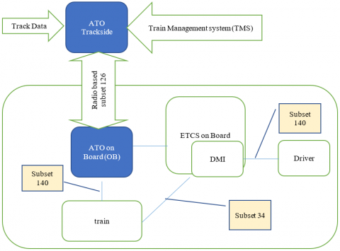
The track, i.e. the global system management of the infrastructure holder, provides two different sets of data being specified respectively in Subset 131 and in Subset 132. The global architecture of the system (see Figure 3) in a nominal functioning can be seen as a three layered one.
Figure 3. Extract of the architecture of ATO over ETCS
On the top, there is the European Train Control System (ETCS) supervision. Particularly in Full Supervision (FS) mode, the ETCS OB system may apply a “service braking” in case of small over-speed. In case of heavy over-speed, the ETCS OB system will trigger an emergency braking, triggering the TRIP mode. At a second level, the driver sends a message to get in Automatic Driving mode, by the means of the Display Machine Interface (DMI): the DMI is the normalized human interface using ERTMS. This message asks to trigger the process towards ATO mode. As detailed in the study [21], Subset 126 details the ATO OB (On Board) - Vehicle Interface, allowing the ATO OB to control the vehicle. AoE specifies the interface between the ATO on board and the physical vehicle in Subset 139. ATO OB – ETCS OB Interface defines the needed data and the corresponding operational protocol allowing exchanges between a software entity running in the automatic train and the hardware and software entities corresponding to the ETCS technical specification. It is detailed in Subset 130.
This Interface includes:
As an example, ATO OB needs to receive train data, which are provided by the driver running the ERTMS/ETCS procedure called “data entry”. Among other information, a data entry provides the length and the nature of the train. Obviously, this information is needed to smartly control the train. In the context of a GoA2 functioning, the driver may send the following orders to ATO OB through the human interface of ETCS OB called DMI:
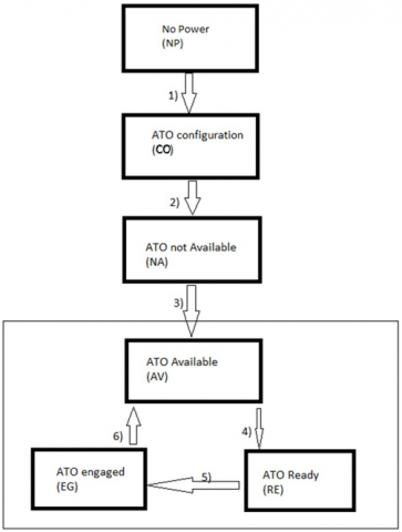
The “ATO Disengage” input is considered as enabled by the ETCS OB when the “ATO engaged” or when the “ATO Disengaging” indication is displayed. Some national signalling systems may benefit from the normalization of interfaces between trackside and on-board systems [19, 22-25]. The table in Figure 4 may be consulted for more information on the ATO mode state management.
3.2 Functional analysis conclusion
What are the advantages of using Subsets 131 and 132 under AoE, using a GoA2 autopilot?
As such, it is the driver who guarantees that the context of the GoA2 operation (“No safety function other than compliance with signs”) is fulfilled by the ATO. When the ATO is running, the work-load of the driver is decreased in such a way that his level of awareness of environmental evolution may increase.
|
1) |
The ATO-OB is powered on. The ATO state changes from NP to CO. The “ATO Selected” indication is displayed |
|
2) |
ETCS data entry process (including ATO Specific Data Entry) is completed and the ATO-OB receives the required data. The ATO state changes from CO to NA. The “ATO Selected” indication is displayed. |
|
3) |
When all the ETCS related Conditions are fulfilled and ATO global infrastructure is detected, the ATO state changes from NA to AV and the “ATO Available” indication is displayed to the driver. |
|
4) |
When all the ATO Engagement Conditions are fulfilled, the ATO state changes from AV to RE and the “ATO Ready for Engagement” indication is displayed to the driver. |
|
5) |
The driver selects “ATO Engage”, the ETCS changes to AD Mode. The ATO state changes from RE to EG. The “ATO Engaged” indication is displayed to the driver and the ATO-OB starts driving the train automatically |
|
6) |
The ATO-OB drives the train. When the train stops, the ATO-OB requests the “Train Holding Brake” application and the “ATO Selected” indication is again displayed to the driver. The state changes from EG to AV. The train is stationary waiting until the ATO Engagement Conditions are fulfilled again. |
|
7) |
Return to step 4) and repeat the sequence until the end of the journey |
Figure 4. ATO states for a nominal scenario, out of draft of Subset 125
3.3 AoE system architecture using SysML
As previously presented, when the system switches from a human driver to an automatic system, abilities of the driving agent change. A consequence is that configuration changes on the track-side and on the on-board systems, using the communication means provided by Subset 126. The current subsection provides a global description of the corresponding architecture using SysML block definition diagrams [27]. It is detailed by presenting the state machine of each block that describes its behaviour and a sequence diagram for each level that describes the interplay between level components. The last layer and its corresponding sequence diagrams are not presented in the current paper. To model the GoA2 AoE System architecture, the system is decomposed into 4 levels (see Figure 5).
Figure 5. Architecture model
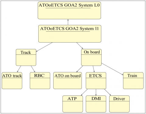
In Figure 6, “ATOoETCS GoA2SystemL0” represents the abstract system, that contains only one block named “ATOoETCS GoA2System”.
Figure 6. State machine of Level 0
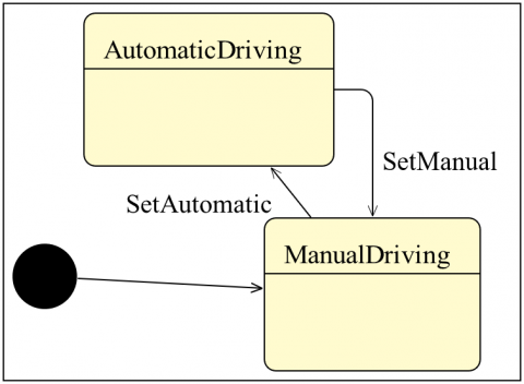
In Figure 7, “ATOoETCS GoA2SystemL1” represents a refinement of the Level 0. It introduces two components, “Track” and “OnBoard”, as specified in Subset 125 [19], and can be seen in the blue components of Figure 3. The behavioral specification of Level1 is shown in Figure 8.
Figure 7. State machines of Level 1
Figure 8. Sequence diagram of Level 1
In Level 2 there are 2 subsystems “Track” and “OnBoard” as components of “ATOoETCS GoA2System” element of level 0.
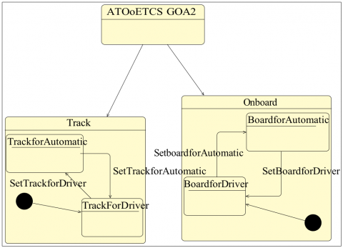
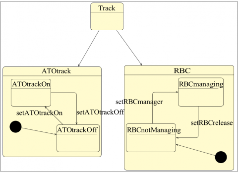
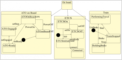
The third level (see Figures 9 and 10) is a decomposition of the second level into five components. Track is decomposed into (ATO-Track, RBC) and Onboard is decomposed into (ATO-Onboard, ETCS and Train). One can notice that in the two first levels, a logical architecture able to manage the various functioning phases is presented. This specification concerns mainly software and automation. At this level, the mechanical part of the system appears with the component train. Messages exchanged between components of Onboard are normalized respectively by Subsets 130, 34 and 139 as shown in the lower part of Figure 3. This specification can be integrated in the port definitions of corresponding Block Definition Diagrams modelling the on-board system description at Level 2. Considering ATO-Track, the track is supposed to be an actor of the system, in other words outside of the system being specified. Nevertheless, interface relationships are sharply specified on the basis of Subsets 131 and 132. Referring to Figure 3, it is clear that while being an actor of the system in the Jacobson’s terminology [27], the track should own an interface (based on Subset 126) compatible with Subsets 131 and 132 (if this interface is detected, then “ATO Available” can be sent), and this interface shall be active for starting ATO-onboard functioning, in such a way that using the specific protocols, the train receives the needed data in the correct format. The interface availability is checked before switching from the initial state towards “ATO available” state of Figure 4, triggering Transition 3 of the table.
Figure 9. State machines of the track components at Level 2
Figure 10. State machines of the on-board components at Level 2
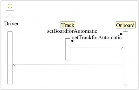
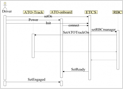
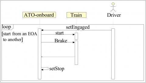
The sequence diagram of the “sub use-case” of the use case “performing running ATO” (see Figure 2) can be consulted on Figure 11. Then a connection based on telecommunication means shall be established and a functional protocol (with respect to Subset 126) shall be initialized before firing Transition 4 switching towards the state “ATO Ready”. The sequence diagram of the use case “perform running ATO and to the sub use-case “stop the travel” while running ATO (see Figure 2), can be consulted on Figure 12. This figure shows message exchanges triggering the state changes of the ATO on Board system (see Figure 10). Comparing Figure 9 and Figure 11, it appears that “setboardforAutomatic” corresponds to a sequence of messages: “setOn, powerOn, init, connect, SetReady, SetEngaged”. In the same time, “SetTrackfor” Automatic is implemented at Level 2 by “setRBCMAnager” and “SetATOTrackOn”. Nevertheless, the refinement relationship is not defined in the standard SysML profile. In the next sub-section, a dedicated profile is used in order to present the hierarchical and modular specification, while respecting the global choreography of messages [28]. In the current subsection, all messages of Level 2 are presented in a single sequence diagram, involving all the sub-components of “Track” and “OnBoard” in Figure 12.
Figure 11. Level 2 sequence diagram for the sub-case “start ATO” of the use case “start travel” of Figure 2
Figure 12. Level 2 sequence diagram for the sub-case “perform travel running ATO” of Figure 2
In the last level of the architecture, ETCS is decomposed into ATP and DMI. Assuming that DRIVER is considered as an agent, ATP and DMI are not presented here. Let us note that the driver may not be a component of the system, because in a Jacobson schema he would be an agent triggering functions by the mean of the DMI (see Figure 2). A more relevant analysis may consider the driver to be a component of a GoA2 system, see the studies [29, 30] to get a theoretical background. Adopting this point of view, the human is not only an agent triggering functions; he is one of the components of the global system (see Figure 5). As a consequence, his operational ability has to be ensured by the system. It means that interactions with the autopilot induce a sufficient level of attention and a coherent understanding of the operating context. These human factor and ergonomic aspects are not considered in the current paper and we referred to the system definition of the system boundaries presented in Figure 2. The current section has provided a SysML model corresponding to a given level of analysis of a draft of Subset 125 that has been simplified for a freight train particular case: the ATP component, providing a critical contribution to the safety of the system was not detailed because it appears in a lower level of the architecture. The model provided in this section corresponds only to the understanding of the authors and cannot be considered as normative specifications. Some modelling artefacts are neglected by the authors in order to simplify models, as an example, the necessary conditions related to the full supervision ETCS mode are not considered despite the fact that they are specified in the table of Figure 4, the current section is only a case study. The following subsection proposes to transform this model into an Event-B model.
3.4 From SysML to Event-B specification
High level architecture (HLA) [31] provides the specification of “technical architecture for use across all classes of simulations”. SysML is a general graphical modelling language. It is a general-purpose architecture modelling language for systems engineering applications. It allows graphical modelling of the HLA of complex systems. However, the semantics of SysML is mainly given in natural language. This is a weak point with regard to rigorous reasoning and critical properties proving. For this reason, a systematic transformation of the SysML model, owning all the previously illustrated qualities for system validation with the help of experts of the system, into an Event-B model provides the two following benefits:
Event-B is a formal method for system modelling, promoted in the highest-level system analysis of the PERF (Preuve d’Évaluation par Retro-modélisation Formelle) approach of the RATP [15]:
“(…) a composite approach is under consideration, combining a top-down approach based on the use of Event-B at system level and a PERF inherited bottom-up approach (…)”
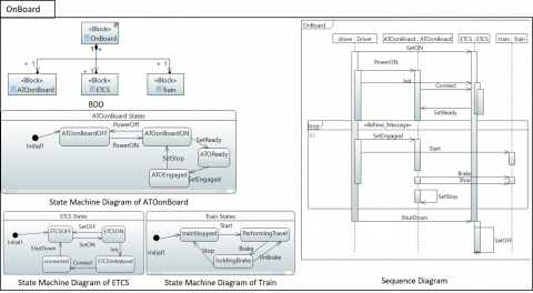
As a consequence, in the railway domain, this modelling tool is well adapted for the formal analysis performed at a system level. Using the tooled methodological framework presented in the study [28], the SysML model of the previous section is transformed into modular Event-B models. The paper proposes an extension of SysML HLA graphical modelling with the mechanisms of model refinement and decomposition of Event-B. Systematic translation rules of the automatic transformation of the extension applied on SysML HLA design models into Event-B models are also provided. In order to illustrate the global approach, the corresponding Event-B generation is transformed from the previous SysML models. Integrating the two sequence diagrams corresponding to Figures 11 and 12 into a single one, the following model is built (see Figure 13).
Figure 13. OnBoard HLA model
|
SYSTEM OnBoard_CONT
SETS ETCS; Train; ATOonBoard; ATOonBoardStates; TrainStates; ETCSStates
CONSTANTS atoonboard, etcs, train, ETCSInitialysed, ATOEngaged, ETCSON, trainStopped, PerformingTravel, ATOonBoardON, ETCSOFF, ATOReady, connected, ATOonBoardOFF, holdingBrake
PROPERTIES train ∈ Train ∧ atoonboard ∈ ATOonBoard ∧ etcs ∈ ETCS ∧ ATOonBoard ={atoonboard} ∧ Train ={train} ∧ ETCS ={etcs} ∧ trainStopped ∈ TrainStates ∧ ATOReady ∈ ATOonBoardStates ∧ holdingBrake ∈ TrainStates ∧ connected ∈ ETCSStates ∧ ATOEngaged ∈ ATOonBoardStates ∧ ATOonBoardON ∈ ATOonBoardStates ∧ PerformingTravel ∈ TrainStates ∧ ETCSOFF ∈ ETCSStates ∧ ATOonBoardOFF ∈ ATOonBoardStates ∧ ETCSInitialysed ∈ ETCSStates ∧ ETCSON ∈ ETCSStates ∧ ATOonBoardON ̸= ATOReady ∧ ATOonBoardOFF ̸= ATOReady ∧ ATOEngaged ̸= ATOReady ∧ PerformingTravel ̸= trainStopped ∧ holdingBrake ̸= trainStopped ∧ ATOonBoardOFF ̸= ATOonBoardON ∧ ATOEngaged ̸= ATOonBoardON ∧ ATOEngaged ̸= ATOonBoardOFF ∧ holdingBrake ̸= PerformingTravel ∧ ETCSOFF ̸= ETCSInitialysed ∧ connected ̸= ETCSInitialysed ∧ ETCSON ̸= ETCSInitialysed ∧ connected ̸= ETCSOFF ∧ ETCSON ̸= ETCSOFF ∧ ETCSON ̸= connected ∧ ATOonBoardStates ={ATOReady, ATOonBoardON, ATOonBoardOFF, ATOEngaged} ∧ TrainStates ={trainStopped, PerformingTravel, holdingBrake} ∧ ETCSStates ={ETCSInitialysed, ETCSOFF, connected, ETCSON} END |
Listing 1. On-Board Event-B context
|
REFINEMENT OnBoard REFINES OnBoard_Interface SEES OnBoard_CONT, ATOoETCS_GoA2SystemL1_CONT, ATOoETCS_GoA2SystemL0_CONT VARIABLES atoonboardState, etcsState, trainState, onboardState INVARIANT atoonboardState ∈ ATOonBoard --> ATOonBoardStates ∧ etcsState ∈ ETCS --> ETCSStates ∧ trainState ∈ Train --> TrainStates INITIALISATION atoonboardState :∈ {atoonboard} → ATOonBoardStates ∥ etcsState :∈ {etcs} → ETCSStates ∥ trainState :∈ {train} → TrainStates ∥ onboardState :∈ {onboard} → OnBoardStates EVENTS SetOFF = SELECT etcsState(etcs)=ETCSON THEN etcsState(etcs):=ETCSOFF END; Shutdown = SELECT atoonboardState(atoonboard)=ATOonBoardON ∧ etcsState(etcs)=connected THEN etcsState(etcs):=ETCSOFF END; SetReady = SELECT etcsState(etcs)=connected ∧ atoonboardState(atoonboard)=ATOonBoardON THEN atoonboardState(atoonboard):=ATOReady END; SetEngaged ref SetBoardForAutomatic= SELECT atoonboardState(atoonboard)=ATOReady ∧ onboardState(onboard)=BoardForManualDriving THEN atoonboardState(atoonboard):=ATOEngaged || onboardState(onboard):=BoardForAutomaticDriving END; PowerOn = SELECT etcsState(etcs)=ETCSON ∧ atoonboardState(atoonboard)=ATOonBoardOFF THEN atoonboardState(atoonboard):=ATOonBoardON END; Start = SELECT atoonboardState(atoonboard)=ATOEngaged ∧ trainState(train)=trainStopped THEN trainState(train):=PerformingTravel END; connect = SELECT etcsState(etcs)=ETCSInitialysed THEN etcsState(etcs):=connected END; Stop = SELECT trainState(train)=holdingBrake THEN trainState(train):=trainStopped END; setOn = SELECT etcsState(etcs)=ETCSOFF THEN etcsState(etcs):=ETCSON END; Brake = SELECT trainState(train)=PerformingTravel THEN trainState(train):=holdingBrake END; Init = SELECT atoonboardState(atoonboard)=ATOonBoardON ∧ etcsState(etcs)=ETCSON THEN etcsState(etcs):=ETCSInitialysed END; SetStop = SELECT trainState(train)=trainStopped ∧ atoonboardState(atoonboard)=ATOEngaged THEN atoonboardState(atoonboard):=ATOonBoardON END END |
Listing 2. OnBoard Event-B machine
In a second step, the Event-B components whose modular design respects the architecture of Figure 5, can be generated (see Listing 1). In the next Event-B model, messages are translated into events and refinement of events is used for representing the implementation mechanisms through the hierarchy of system components (see Listing 2). As refinement is an Event-B fundamental concept to master complexity, it was proposed to add it in SysML models. This has led to define a new profile, called Refinement, on Sequence Diagrams [18]:
“(…) This profile allows to define refinement links between the behavior of subsystems and the behavior of their parent system. It defines a stereotype called Refines Message with an attribute Refined Message. More precisely, the stereotype can be applied on a message exchanged between sub-systems to specify that it refines a message of the parent system. (…)”
This refinement mechanism is used to model the relationship between the “setBoardforAutomatic” event (see Figure 13) which is refined by the “setEngaged” event at a lower level of the architecture (see Figure 10). The use of the Refines stereotype Refines “Message” can be seen on the “loop” specification of the Figure 13 and its Event-B translation is reported in the “Events” section of the Listing 2.
In this paper, we only use the transformation rules proposed by Bougacha et al. [28]. Building a hierarchical HAL model using the multi-layer methodology [28] was not systematically applied in this paper. Only few components were modeled using SysML for illustration and clarification goals.
The paper proposes an alternative approach to model-based testing. Starting from a SysML model, the main architectural assumptions of the considered system may be formally validated through invariant fulfilment of an Event-B model. Moreover, a refinement link, for a particular implementation of the considered specification and a given model of the norm, contributes to the global conformity. A railway case study is provided in order to illustrate the methodology. It consists of using an automatic operation system over ETCS, while a driver is in charge of safety relevant operations. Analyzing normative documents, assumptions of functioning are explained in a first part of the paper. In a second part, a SysML model of the higher levels of the architecture is described. This SysML model is expressed in a dedicated profile and then transformed into Event-B specifications. This paper presents the main elements of an approach which is correct-by-construction. Applying the systematic multi-layered approach of the study [28] on the AoE case study may provide a more relevant document for software engineering scientist. It may provide an illustration of the methodology on a real size example. Moreover, this application may be used as a benchmark to evaluate concurrent tools and approaches promoted by the scientific community. Following this point of view, it may be useful to present a system analysis built directly on Subset 125 [19]. The case study of the presented paper is an extended version of a railway conference paper [20] presenting AoE as a building brick towards GoA4 autonomous trains. This aspect is not developed any more in the current document, but the underlying vision of this previous paper should be adapted to a wider audience than transport scientists. Starting from this context, the full specification of the methodology application on this case study is published (https://github.com/RacemBougacha/ATO-over-ETCS.git). In order to apply a KAOS methodology [32], it is obvious that further work concerning model engineering are needed. Considering a real size application, a tooled framework assisting the alignment process between high level goals and architecture component would be a precious help. Finally, the added value of the proposed alternative to classical model-based testing still needs to be evaluated from a scientific and technological point of view. Among other points, the reliability of the transformation process, promoted by the current study, is a critical point where formal proofs can contribute efficiently [33].
[1] SUBSET-026: System Requirements Specification. Std, UNISIG. (2016).
[2] SUBSET-076-6-3: Test Sequences, Version 3.0.0. Std, European Railway Agency. (2015).
[3] SUBSET-094: Functional Requirements for an On-Board Reference Test Facility, Version 3.0.0. Std, European Railway Agency. (2014).
[4] Collart-Dutilleul, S., Pereira, D.I.D.A., Bon, P. (2022). Designing operating rules for ERTMS transnational lines. In: Collart-Dutilleul, S. (eds) Operating Rules and Interoperability in Trans-National High-Speed Rail. Springer, Cham. https://doi.org/10.1007/978-3-030-72003-2_6
[5] Bernabé, C.H., Silva Souza, V.E., Almeida Falbo, R.D., Guizzardi, R.S.S., Silva, C. (2019). GORO 2.0: Evolving an ontology for goal-oriented requirements engineering. In: Guizzardi, G., Gailly, F., Suzana Pitangueira Maciel, R. (eds) Advances in Conceptual Modeling. ER 2019. Lecture Notes in Computer Science(), 11787. Springer, Cham. https://doi.org/10.1007/978-3-030-34146-6_15
[6] Debbech, S., Bon, P., Dutilleul, S.C. (2019). Towards semantic interpretation of goal-oriented safety decisions based on foundational ontology. Journal of Computers, 14(4): 257–267, 2019. https://doi.org/10.17706/jcp.14.4.257-267
[7] Delligatti, L. (2013). SysML Distilled: A Brief Guide to the Systems Modeling Language. Addison-Wesley.
[8] Bernardi, S., Donatelli, S., Merseguer, J. (2002). From UML sequence diagrams and statecharts to analysable petri net models. In Proceedings of the 3rd International Workshop on Software and Performance, pp. 35-45. https://doi.org/10.1145/584369.584376
[9] Trowitzsch, J., Zimmermann, A. (2006). Using UML state machines and Petri nets for the quantitative investigation of ETCS. In Proceedings of the 1st International Conference on Performance Evaluation Methodolgies and Tools, pp. 34-es. https://doi.org/10.1145/1190095.1190138
[10] Jabri, S., El Koursi, E.M., Bourdeaud’huy, T., Lemaire, E. (2010). European railway traffic management system validation using UML/Petri nets modelling strategy. European Transport Research Review, 2(2): 113-128. https://doi.org/10.1007/s12544-010-0030-5
[11] Abrial, J.R., Butler, M., Hallerstede, S., Hoang, T.S., Mehta, F., Voisin, L. (2010). Rodin: An open toolset for modelling and reasoning in Event-B. International Journal on Software Tools for Technology Transfer, 12: 447-466. https://doi.org/10.1007/s10009-010-0145-y
[12] Stankaitis, P., Iliasov, A., Kobayashi, T., Aït-Ameur, Y., Ishikawa, F., Romanovsky, A. (2021). A refinement-based development of a distributed signalling system. Formal Aspects of Computing, 33: 1009-1036. https://doi.org/10.1007/s00165-021-00567-y
[13] Lecomte, T., Comptier, M., Molinero, J., Sabatier, D. (2020). Ensuring Safety with System Level Formal Modelling. In: Margaria, T., Steffen, B. (eds) Leveraging Applications of Formal Methods, Verification and Validation: Applications. ISoLA 2020. Lecture Notes in Computer Science(), 12478. Springer, Cham. https://doi.org/10.1007/978-3-030-61467-6_25
[14] Behm, P., Benoit, P., Faivre, A., Meynadier, J.M. (1999). METEOR: A successful application of B in a large project. In World Congress on Formal Methods, 1708: 369-387.
[15] Bonvoisin, D. (2016). 25 years of formal methods at RATP. Proceeding of International Railway Safety Council (IRSC2016) Paris 2-7 October, 2016, pp. 1-8.
[16] Yar, A., Idani, A., Ledru, Y., Collart-Dutilleul, S. (2022). Visual animation of B specifications using executable DSLs. In Proceedings of the 25th International Conference on Model Driven Engineering Languages and Systems: Companion Proceedings, pp. 617-626. https://doi.org/10.1145/3550356.3561585
[17] Ladenberger, L., Bendisposto, J., Leuschel, M. (2009). Visualising event-B models with B-motion studio. In: Alpuente, M., Cook, B., Joubert, C. (eds) Formal Methods for Industrial Critical Systems. FMICS 2009. Lecture Notes in Computer Science, 5825. Springer, Berlin, Heidelberg. https://doi.org/10.1007/978-3-642-04570-7_17
[18] Bougacha, R., Laleau, R., Bon, P., Collart-Dutilleul, S., Ben Ayed, R. (2023). Modeling train systems: From high-level architecture graphical models to formal specifications. In: Kallel, S., Jmaiel, M., Zulkernine, M., Hadj Kacem, A., Cuppens, F., Cuppens, N. (eds) Risks and Security of Internet and Systems. CRiSIS 2022. Lecture Notes in Computer Science, 13857. Springer, Cham. https://doi.org/10.1007/978-3-031-31108-6_12
[19] SUBSET-125: ATO over ETCS - System Requirements Specification. (Issue: 0.1.0). Std, UNISIG. (2018).
[20] Bon, P., Collart-Dutilleul, S., Bougacha, R. (2022). ATO over ETCS: A system analysis for freight trains. Computers in Railways XVIII: Railway Engineering Design and Operation, 213: 37-47.
[21] Kuhn, M. (2019). System architecture description, smartrail 4.0 architecture. Technical Report, Smartrail 4.0.
[22] SUBSET-126: ATO over ETCS - ATO-OB/ATO-TS FFFIS Application Layer Specification. (Issue: 0.0.16). Std, UNISIG. (2018).
[23] SUBSET-130: ATO over ETCS - ATO-OB/ETCS-OB FFIS Application Layer. (Issue: 0.1.0). Std, UNISIG. (2018).
[24] SUBSET-139: ATO over ETCS - ATO-OB/ Vehicle Interface Specification FIS. (Issue: 0.0.8). Std, UNISIG. (2018).
[25] Buurmans, K. (2019). Automatic train operation over legacy automatic train protection systems: A case study on the Groningen-Buitenpost line. Technical Report, Delft University of Technology. Master of Science in Civil Engineering at the Faculty of Civil Engineering and Geosciences, Department Transport & Planning of Delft University of Technology.
[26] SNCF. Specific driver rulebook for operating train in France, “Référentiel conducteur de ligne” (confidential document: Industrial property of SNCF).
[27] Holt, J., Perry, S. (2019). SysML for Systems Engineering: A model-based approach. (3rd Edition). Computing and Networks Series, Institution of Engineering and Technology, SBN978-1-78561-554-2.
[28] Bougacha, R., Laleau, R., Collart-Dutilleul, S., Ayed, R.B. (2022). Extending SYSML with refinement and decomposition mechanisms to generate EVENT-B specifications. In: Aït-Ameur, Y., Crăciun, F. (eds) Theoretical Aspects of Software Engineering. TASE 2022. Lecture Notes in Computer Science, 13299. Springer, Cham. https://doi.org/10.1007/978-3-031-10363-6_18
[29] Vanderhaegen, F. (2017). Towards increased systems resilience: new challenges based on dissonance control for human reliability in Cyber-Physical&Human Systems. Annual Reviews in Control, 44: 316-322. https://doi.org/10.1016/j.arcontrol.2017.09.008
[30] Wilson, J.R., Farrington-Darby, T., Cox, G., Bye, R., Hockey, G.R.J. (2007). The railway as a socio-technical system: Human factors at the heart of successful rail engineering. Proceedings of the Institution of Mechanical Engineers, Part F: Journal of Rail and Rapid Transit, 221(1): 101-115. https://doi.org/10.1243/09544097JRRT78
[31] Dahmann, J.S. (1997). High level architecture for simulation. In Proceedings First International Workshop on Distributed Interactive Simulation and Real Time Applications, Eilat, Israel, pp. 9-14. https://doi.org/10.1109/IDSRTA.1997.568652
[32] Matoussi, A., Gervais, F., Laleau, R. (2010). An event-B formalization of KAOS goal refinement patterns. Technical Report, HAL CCSD.
[33] Idani, A., Ledru, Y., Anwar, A. (2013). A rigorous reasoning about model transformations using the B method. In International Workshop on Business Process Modeling, Development and Support, Springer, Berlin, Heidelberg, pp. 426-440. https://doi.org/10.1007/978-3-642-38484-4_30