Iynes Laouni* | Said Mazouz
© 2021 IIETA. This article is published by IIETA and is licensed under the CC BY 4.0 license (http://creativecommons.org/licenses/by/4.0/).
OPEN ACCESS
The aim of this research is to develop a material that will improve indoor comfort by eliminating the effect of hot walls during the summer and lowering the amount of energy consumed by air conditioning. It also aims to promote enough thermal autonomy to maintain thermal comfort in hot arid areas, such as Biskra's climate in southeastern Algeria, as well as to provide designers with a healthy, durable, and long-lasting material, solid, and low-cost material option. The thermal properties of this material, including the proposed combination and manufacturing procedure for these compressed and stabilized earth bricks, will be demonstrated. The study's prototype will be described.
compressed and stabilized earth brick (CSEB), ambient temperature, experimentation, thermal simulation, sustainable building material
Energy is a determining factor for the survival of societies and is essential for the satisfaction of daily needs and economic and social development. However, this energy is mainly based on fossil fuels (gas, oil and coal), which are not renewable and are expected to run out in the medium term. Fossil fuels emit gases responsible for the proven increase in the greenhouse effect and climate change, which are, without a doubt, the most significant challenges for humanity. The latest reports by experts from the IPCC are unanimous that the exponential growth of greenhouse gases during the last decades has contributed to modifying the climatic conditions on the planet [1]. These greenhouse gases, such as CO2, which will see its concentration double by 2050, will induce an increase of a few degrees in our regions [1, 2]. The production of the necessary energy is becoming increasingly expensive for the State and hurts the environment. The requirement for a large number of new buildings to accommodate rising population and living standards clashes with the need to combat global warming and biodiversity loss. To address this dual dilemma, a more circular economy must be established by widely utilizing a combination of alternative low-carbon construction materials, technologies, and practices. Centuries of empirical experiences have resulted in a range of approaches to apply earth, l'architecture en terre is encore un marché de niche bien qu'incarnant tous les attributs du meilleur matériau de construction pour affronter the current climate and economic crisis [3].
In an arid and semi-arid climate, such as that of Biskra in southeastern Algeria, the major problem that causes thermal discomfort in summer is excessive heat. Consequently, the cooling of the space is the most desirable, the most sought after and the most worrying factor for users. This imposes the use of electrical cooling devices for a more extended period than that of heating, resulting in high consumption of electrical energy a heavy bill to pay for users, and a significant contribution to air pollution, environmental pollution, and global warming phenomenon. This seems to be the result of the industrialization typification and standardized construction, coupled with inappropriate use of materials for arid climates. Faced with the danger caused by global warming, public opinion and political decision-makers are increasingly aware of the need to take this scourge into account in development plans such as that of the building [4]. Other possibilities for cooling the space, which are non-polluting, more sustainable and less expensive, should be explored and allow the user to enjoy good thermal comfort. Vernacular architecture, which can be considered as a school from which to learn some lessons, has previously proved its degree of climatic adaptability and resistance in hard climates such as hot and arid climates, ensuring very good thermal comfort at the lowest possible cost [4]. Many new materials, such as concrete, have been developed due to technological advancements, relegating the original materials to the status of "primitive." Earth, stone, and wood were the first building materials used, but many new materials, such as concrete, have been developed due to technological advancements, relegating the original materials to the status of "primitive". Little by little, we have come to forget the advantages of the earth as a building material. Faced with ecological and social problems, we are gradually coming back to it. On the other hand, the share of earthen construction in the world is estimated at 30%, mainly concentrated in so-called "poor" countries [5]. Raw earth is regaining interest among architects, engineers, and policymakers for the construction of dwellings in industrialised countries after being nearly abandoned at the close of World War II. Growing ecological consciousness and the promotion of construction practices that reduce energy usage and carbon emissions are driving this revival. Raw earth has fascinating thermo-hygro-mechanical qualities that can help reduce the environmental effect of buildings not only during construction but also during their lifetime. Nonetheless, one of the barriers to the widespread use of raw earth in construction is that [6, 7].
This architecture, considered heritage, conveys within its adaptation mechanisms to the climate that should be understood. Among the most promising techniques is the use of earth material in construction. With this in mind, this research aims to reconcile man with his environment and with an ancestral material that should be revisited and improve its mechanical and physicochemical properties for the adaptation to modern construction requirements. The objectives of the research are as follows:
1. To produce a healthy, durable, solid and low-cost material that can be mass-produced, industrialized with a new and rapid technique. This material will take the form of a compressed and stabilized earth brick (CSEB), adapted to the arid region.
2. Reduce energy consumption for air conditioning and, above all promote sufficient thermal autonomy to maintain thermal comfort despite the extent of overheating by eliminating or, at least, reducing the "hot wall" effect during summer.
This research is based on three phases:
• Development of the building material based on SCEB earth (compressed and stabilized earth brick).
• Experimentation: Test this material thermally with a reduced model.
• The simulation of the different combinations of the prototype with the TRNSYS 17 © software.
The literature review reveals the existence of two groups: the first focuses on the thermal performance of earth building material, especially in hot and arid climates such as the Algerian one, where earthen construction has been prevalent throughout its long history particularly, in rural areas and arid regions. Building materials play an important role in sustainable design, both in terms of thermal performance and environmental impact [6]. Today, we are witnessing a resurgence of interest in this material, which can be explained, first of all, by the desire to carry out part of the program devoted to rural housing (around 40%), then by the desire to adopt the legislation to the new international context in terms of sustainable development [8]. However, because of the world heritage of earthen construction traditions, there are many construction techniques with an infinite number of variants adapted to the quality of the earth and the level of development of know-how, reflecting the identity of the places and cultures. The CRATerre group [7] created a diagram with twelve techniques for using soil for construction. Eight techniques are used daily and constitute the main techniques: adobe, pisa, earth-straw, cob, shaped earth, extruded earth, compressed earth blocks
Guillaud and Houben (1995) have schematically listed the twelve main techniques in a "wheel" of earthen construction techniques. However, they still specify that there are about a hundred in reality. Because earthen construction is a material that is crowded underfoot daily, the earth can only be used in construction if it has good inherent cohesion, primarily due to clay, which acts as a natural binder [8]. Brick is the most used element in construction. However, its fragility continues to hinder its mechanical behaviour; additionally, its low thermal resistance provides unsuitable thermal comfort for building users [5]. For this purpose, the use of cement or lime in stabilizing the earthen material, in general, is a fairly well-known domain thanks to the critical laboratory work and in-situ achievements. These researches made it possible to know the mechanisms of reactions between the earthen material and these binders and their effects on the properties of the earthen material. As a result, unlike concrete, it is not possible to anticipate the performance of an earthen wall based on its fundamental composition; instead, performance should be determined by performance-based tests. However, decision tools for planning authorities and earthwork contractors to assess the potential of excavated soils for construction can be proposed. However, technical validation of the material remains the responsibility of a project manager specializing in earthen architecture [9].
The second research group approaches thermal comfort and increased energy efficiency in hot and dry climate zones. Thermal comfort is probably the most important and the easiest to define among the IEQ parameters. For occupants to produce at their full capacity, their working space must be thermally comfortable. However, thermal comfort is based on the thermal adaptation of occupant individuals, which is correlated to factors such as geographic location, climate, periods of the year, gender, race and age [10]. In addition, thermal comfort directly impacts the building's energy consumption, because any discomfort sensation of the occupant will lead to adjusting the controls to non-optimal levels [11]. This thermal comfort is influenced by six factors, among which four can be classified as environmental. The parameters include air temperature, the average radiant temperature, relative air humidity and airspeed; the two other parameters are classified as personal factors and have human metabolic rates and clothes induced isolation Katafygiotou [12]. All the previously mentioned factors are considered during the design of the building itself [13]. Other parameters such as gender, age and climatic conditions impact the thermal comfort perceived by the occupant. The location and typology of the building as well as the exterior climate and the season influence also the thermal comfort of the occupants [14].
Human beings have strived to create interior environments in which they can feel comfortable. Human health is primordial when it comes to evaluating the general comfort of the domain. If for any reason, the built environment leads to sickness or hurts the health of the occupants, it is then a subject of preoccupation. It can indicate a default in the design or the building system [15]. The human body tries to maintain a temperature of approximately 37℃. The temperature is maintained through heat exchange between the human body and the environment through convection, radiation and evaporation [16]. The two postures mentioned above, without being exhaustive, summarise and group the initiatives in this area. The re-appropriation of the earth material remains conditioned by sufficient knowledge of the local climate, coupled with knowledge of earthen construction techniques, including shaping, a dosage of the constituents of SCEB. The latter is presented as the synthesis of two methods: compression, which produces raw CEC, and stabilization, SEC the mixture and the methods adopted are the key to successfully making a compressed and stabilized earth brick, especially since in Algeria there is not yet a factory for this type of material. Prototypes of raw compressed earth bricks CEC or stabilized earth bricks SEC were made in the laboratory, but they were not thermally tested. As a result, there were no recommendations for producing a thermally efficient material for the region of southeastern Algeria. The experience is made using raw materials available in the southeastern region of Algeria, and can be generalized over southwestern Algeria and all areas of the world, which have a dry and arid climate such as Egypt, Morocco, and Iran. Yemen Mexico … etc.
2.1 Material development
The nature of the soil and that of the binders used as stabilizers and the compaction stress are fundamental parameters, which influence the behaviour of SCEB Used materials.
2.1.1 Used materials
This technique is a modern evolution of the moulded earth block, more commonly referred to as adobe block. Instead of being moulded by hand in a wooden cover, the blocks are obtained by compressing the earth, slightly damp, in a metal press. Compared to the hand-moulded block, BTC is very regular in shape and dimensions, denser, and exhibits better resistance to compression and water [17]. The materials used in the manufacture of SCEB are soil, crushed sand (dune sand), cement, and water. We will only present the results of the study of the characteristics of the components of the material, the dosage, the mixture adopted, the shaping method, and the technique adopted for drying.
a-Soil
The used soil comes from the region of Biskra (Algeria); it was chosen based on its availability and abundance in the area.
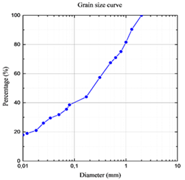
Before testing the soil, it is clipped to 2 mm [18] indicated that the thinnest elements should not be allowed to form nodules more prominent than 10 mm; the presence of 50% of nodules having a 5 mm or superior dimension may reduce by half the compression resistance. According to the granulometric graph of the soil (see Figure 1), the used ground is located within the limit zone recommended by the compressed earth block standard XP P 13-901. This norm for soil is destined for the fabrication of CEC. That it should not be too clayey at the risk of causing shrinkage cracks weakening the blocks (% 2μm <30%) [19].
Table 1. Densities of used soil
|
Apparent soil density (kg/m3) |
Absolute soil density (kg/m3) |
|
1211 |
2580 |
The Atterberg's limits allow the analysis of variations in the consistency of fine soils as a function of water content. As for the granularity, statistical studies were carried out to define the Atterberg limits best suited for the earth blocks and to predict the constructive possibilities of a soil quickly. Mango-Itulamya [20], The defined tests are carried out on the soil mortar (d <0.4 mm) (see Table 2) according to the procedure of standard NF P 94 051.
Figure 1. Granulometric curve of the soil
The obtained results for the used soil show that the plasticity limits are almost within limits best suited for compressed earth blocks (standard XP P13-901). The standard recommends that the soil must have a minimum of plasticity, ensuring cohesion between the grains of the material during compaction (2μm> 5%).
Table 2. Atterberg's limits of used soil
|
Atterberg limits |
||
|
Liquidity limit LL (%) |
Plasticity limit PL (%) |
Plasticity index PI (%) |
|
35 |
22 |
12 |
According to the classification of the "texture triangle" of the INRA [21, 22], we can say that it is sandy loam soil. It is generally well suited for soil stabilization: the earth must have, after shaping, an excellent natural cohesion, that is to say, that the clay content must be high enough (greater than 10%; this is the case of our soil which has 16% clay). It must also contain a mineral skeleton (sand-gravel), ensuring effective action of the cement. Our soil contains 71% sand, 23% silt and 16% clay; the value of methylene blue indicated 1.37, so the nature of the soil used is sandy loam.
Chemical analysis can determine the content of harmful elements such as sulphates. The most frequently encountered sulfate in natural soils is calcium sulfate (anhydrite and gypsum). Its presence is associated with the degradation of earthen construction. The intense swelling related to the hydration of the anhydrite and the solubility of different compounds is then questioned. In the case of compressed and stabilized earth blocks, sulphates can also attack the hardened cement inside the material, particularly when it comes into contact with water. In this case, a specific study for soils containing more than 2 to 3% sulphates must be made.
The mineralogical analysis is also essential to differentiate clay soils. The analyses of the chemical and mineralogical compositions are carried out.
Table 3. Mineralogical analysis results of the soil used
|
Minerals |
quartz |
Gypsum |
muscovity |
kaolinite |
|
Contents (%) |
30 |
29.5 |
------- |
6 |
|
Minerals |
Feldespat k |
Ferruginous minerals+ RX background |
calcite |
|
|
Contents (%) |
4 |
0.9 |
30.06 |
Mineralogical analysis revealed the presence of a high level of gypsum (30.5%), which explains the high level of sulfur trioxide in the soil (see Table 3). The soil also contains considerable rates of quartz and calcite, while the Kaolinite content is low.
Soils can contain organic matter (micro-organism, hummus, etc.); certain humic acids are harmful in the event of stabilization because they delay or cancel the setting of hydraulic binders.Because organic matter is not compressible, it should not be used in large quantities, as this will limit the soil's compressibility, even if it is unstabilized [20]. As a general rule, until more reliable knowledge has been acquired, it has been accepted not to use soil containing more than 2% organic matter, and soil containing 1% is considered risky. Organic matter [23, 24]. Vénuat proposed another threshold "fixing, for lack of a better term, the limit not to be exceeded for the treatment of a floor at 2%. This limit corresponds to a total organic matter content [25]. Kujala proposes a humus threshold of 2% for delay in setting and 3.5% for inhibition [22, 26]. Tremblay indicates a content of 3% organic matter as a stabilization limit [27, 28]. Analysis of our soil revealed the presence of 1.02% organic matter; this rate does not exceed 2%, which is the limit recommended by Doat [23].
This measurement was determined using a pH meter on a suspension of 10 grams of dry material in 100 millilitres of deionized water. Measurement of pH can provide valuable information on the predominance of evolved organic matter or carbonates. Analysis of our soil has shown that its pH is 8.3. According to Vilenkina and Guettala, for soil to be suitable for stabilization, it must have a pH greater than 6. If the pH is less than 6, pretreatment of the soil is essential [29, 30]. In general, soils with a high pH will have better resistance; this is the case with our soil.
b-Crushed sand
The sand used in the bricks mix is crushed sand (0/3) from quarries in the Biskra region (Algeria). It was mainly used for granular soil correction. The physical characteristics of the sand were determined according to AFNOR standards. The granular composition of the sand is shown in the following table (see Table 4).
Table 4. Granular soil composition
|
$A p p D$ |
$A b s D$ |
Distribution of grain size (%) |
FM |
SE (%) |
|||
|
0.01-0.08 mm |
0.08-1.25 mm |
1.25-5 mm |
Visual |
To the piston |
|||
|
1445 |
2600 |
3.25 |
52.83 |
43.92 |
3.08 |
66.2 |
62.5 |
c-Cement
Given the high sulphate content in the soil studied, and to have good durability of the bricks, we used the cement CPA-CEM I 42.5 ES (cement resistant to CRS sulphates), composed of 95% clinker and 5% gypsum. Chemical analysis (see Table 5) of the clinker shows that it complies with standard NFP 15-301. The potential mineralogical composition of clinker is calculated (see Table 6) according to Bogue's empirical formula [31].
Table 5. Cement chemical analysis
|
$\mathrm{SiO}_{2}$ |
$\mathrm{Al}_{2} \mathrm{O}_{3}$ |
$\mathrm{Fe}_{2} \mathrm{O}_{3}$ |
CaO |
MgO |
$\mathrm{SO}_{3}$ |
|
22.17 |
4.53 |
5.04 |
64.55 |
1.02 |
1.34 |
|
|
|||||
|
CT |
$\mathrm{K}_{2} \mathrm{O}$ |
$\mathrm{Na}_{2} \mathrm{O}$ |
Free lime |
Loss on ignition |
Insoluble residues |
|
0.00 |
0.42 |
0.21 |
1.09 |
0.94 |
0.8 |
|
$C_{3} S$ |
$C_{2} S$ |
$C_{3} A$ |
$C_{4} A F$ |
|
51.20 |
21.16 |
3.10 |
12.42 |
Table 6. Cement characteristics
|
Cement designation |
Apparent density |
Absolut density |
|
CPA-CEM I 42.5 ES |
1.144 |
3.232 |
d-Water
The water used in the mixtures is water, which contains a few sulfates and has a temperature of 20 ± 1℃. Its quality meets the requirements of standard NFP 18-404.
e-Unchopped barley straw used for insulation
Barley straw is abundant in the Biskra region. According to research, the initial length of the straw varied between 5 and 60 cm. There are 5 to 6 nodes on the mature plant. The internodes, which account for nearly half of the straw's mass, provide mechanical resistance. In contrast, the knots and leaves, which contain more minerals and less cellulose than the internodes, have lower mechanical strength (see Table 7).
Table 7. Barley characteristics
|
Characteristics |
Unity |
Value |
|
Apparent density |
$\mathrm{Kg} / \mathrm{m}^{3}$ |
215 |
|
Water absorption |
% |
422 |
|
Diameter |
mm |
1-4 |
|
Length |
mm |
10-40 |
2.2 Making the bricks
2.2.1 Specific material
According to the method proposed by the APMC for the preparation of the mixtures, it was also based on the findings of Guettala et al. [26, 29], who found that the sand concentration in CEC has no impact on mechanical strength, but dosages between 25% and 40% have given the best results. As a result, 30%-crushed sand was introduced into the mixture used in this study.
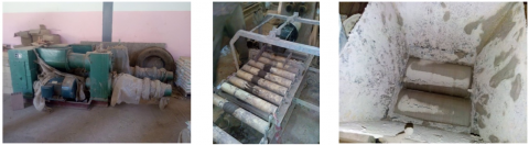
The weight of the full dry mixture for each block is kept constant throughout this investigation; it is predicted to be 2,500 kg for the construction of the bricks, and a mold was produced based on the model. It is composed of hardened steel and consists of five parts with a combined volume of 10x10x20 cm3. The mould has a piston attached to ensure that the press's compaction stress is transferred to the mixture. A diagram of the mould inside the press is shown in Figure 2.
The type of treatment is carried out on too wet and plastic soils. Lime alone is used first at low levels, then cement. The two binders are not competitors but complementary. A pretreatment with lime allows the soil to dry out too wet it becomes pulverulent and friable in the presence of lime, making it more suited for future mixing with cement. It achieves mechanical resistance from the first days of treatment because its hydration kinetics are faster than limes. There has never been any investigation of the mechanisms that govern this treatment (see Figure 6). The cement's release of portlandite Ca (OH) 2 in solution should have the same stabilizing effect as lime. The hydrates created by the free lime and the cement's portlandite will clump with those formed by the dissolved cement [26].
2.3 Mixtures
Based on studies by Mesbah et al. [3], static compaction is better suited to clay soils, thus determining the ideal water content for compaction is not the same as selecting the optimum water content for BTC manufacturing. As a result, we decided to use the press directly and apply static compaction.
According to the method proposed by the CMPA for the preparation of the mixtures, it was also based on the study carried out by Guettala. [29], the research found that the amount of sand in CEC has minimal effect on mechanical strength, but that dosages between 25% and 40% produce the optimum outcomes. As a result, 30% crushed sand was added to the mixture utilized in this experiment.
Throughout this investigation, the weight of the overall dry mixture for each brick is kept constant; it is assumed to be 2.5 kg.
2.3.1 Mixture compaction
Usually, the mixtures are compacted in the static single-acting mode using a hydraulic press: the lower plate of the press moves driving the assembly - mold + mixture + piston, the upper plate remains fixed (see Figure 3). The operation is carried out until the desired pressure reading screen is displayed. Throughout this study, a compaction stress of 5 to 10 MPa was applied. On the other hand, the blocks in this study were created in a dynamic press, which kneads and compacts the mixture at a pressure of 10 MPa. (We used a parallelepiped mold instead of a cylindrical mold.)
Figure 2. Mechanical device for compaction
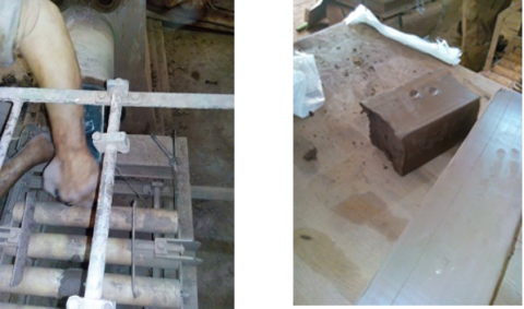
Figure 3. The unmolding is done immediately after compaction
2.3.2 The bricks cure
As with concrete, the strength of a soil binder increases with age. Not all soils behave the same, but a 10-day cure period is essential during this time; the material is kept in a damp environment, out of direct sunshine, and protected from the wind to prevent it from drying out too quickly. Blocks should be covered with plastic film for the first few days before use in actual storage conditions (See Figure 4).
Figure 4. The blocks protected with plastic
After unmolding, the block is taken manually with care, avoiding touching the edges because of its fragility; it is then covered with a plastic film to ensure its tightness. To promote maximum hydration of the binder, the block is then stored without plastic but always in the shade for another 10 days, and every three days, they are turned over for uniform drying of the blocks.
Finally, after the curing period and before testing the SCEBs (see Figure 5), they should be dried one last time to reach a constant mass.
Figure 5. The SCEBs after the curing period
3.1 Results of experimentation
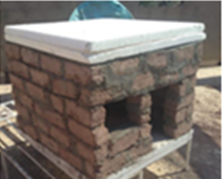
The experimental prototype called prototype (A) is a cube of (1.00 X 0.70X 1.00 m) of the interior edge). A 5 cm or 10 cm thick double layer of rigid polystyrene is used to insulate the slab and the floor. The north-south direction of the cell (The most unfavorable facade has been the main facade south facing.). Metal supports were used to raise the structure 50 cm off the ground, as indicated in Figure 9. In the wall on the south side, an opening was made to allow sliding of the measuring instruments (door) 30/30 cm wide and high and a door 42 cm high and 30 cm wide. The two prototypes are far enough apart to avoid the shadow effect. The internal surface temperature of the south wall will be taken since it is the most unfavourable wall and exposed to the sun all day.
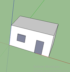
Prototype A is a cell made with SCEBs without insulation (WI) (see Figure 6).
Prototype B is a cell made with SCEBs with insulation (I) (see Figure 7).
Figure 6. Prototype A
Figure 7. Prototype B
3.1.1 Temperature measurement
It's also worth noting that the prototypes are set in an urban setting in Biskra, with the two cells sharing the same climatic conditions and southern orientation. The distances between the cells have been kept constant to avoid casting shadows. The measurements were taken on 01/11/21/31 in August for four representative days. From 6 am to 8 pm, two-hourly measurements were taken for 15 hours (Tex in the shade at the height of 1.2 m). The device used in this study and the Testo 480 (see Figure 8).
Figure 8. TESTO 480
Climatic data used in the experimental work: Biskra is located in the southeastern region of Algeria (latitude + 34.48° N and longitude + 5.73° East). In the summer, it has a hot and dry climate with frequent clear skies and little humidity. The importance of direct and diffuse radiation cannot be overstated. The days are exceptionally long, and around the summer solstice, the sunshine lasted nearly 16 hours.
3.1.2 Results of temperatures measured
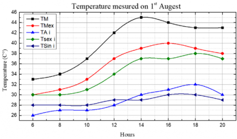
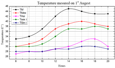
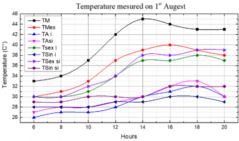
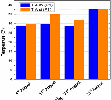
Ambient temperatures with insulation (Ta i) (see Figure 9A) and internal surface temperatures with insulation (Tm ex) (see Figure 9B) are much lower than the average outside temperature in prototype B with insulation (see Figure 9C).
In the morning (8 am to 12 pm), the ambient and surface temperatures for the two prototypes are identical, however in the afternoon, an increase of two degrees is noted (See Figure 9D).
• The ambient temperatures of the prototype with insulation (prototype B) and its surface temperature are very close, registering a difference of 1 degree; on the other hand, the outside temperature is very high (difference of 4℃ to 6℃). (See Figure 9).
With a difference of 1 degree in the morning and 3℃ to 4℃ in the afternoon, prototype A's ambient and surface temperatures without insulation follow the same curve (See Figure 9).
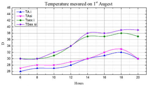
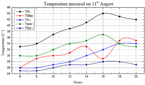
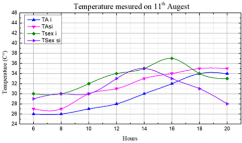
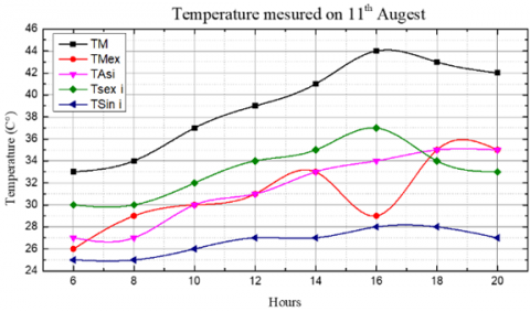
The ambient (Ta i) (See Figure 10A) and surface (TA si) (See Figure 10B). Temperatures of prototype B with insulation follow the same curve in the morning with a difference of 1℃, on the other hand, in the afternoon, from 12 h, ambient temperatures increase every two hours of 2℃ reaching a difference of 5℃ to 6℃ around 5-7 pm (See Figure 10C).
• Ambient temperatures without insulation (prototype A) follow the same curve as ambient temperatures (See Figure 10D) for prototype B with an increase of 1℃ from (8-9h) and (18-20h) and from 2 to 3 degrees between (10-19h)
• The surface temperatures of prototype A (without insulation) reach their maximum of 37° at 4 pm and drop to 33℃ at 8 pm.
Temperature Results Measured on August 1
August 01
A
B
C
D
Figure 9. Temperatures measured on August 1
Temperature Results Measured on August 11
August 11
A
B
C
D
Figure 10. Temperature measured on August 11
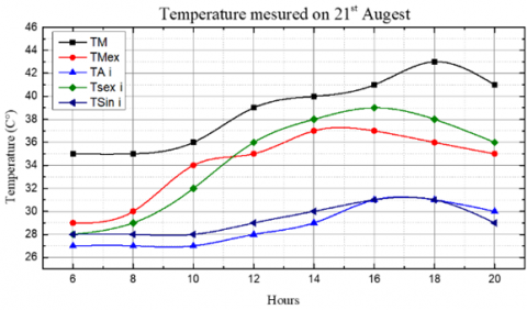
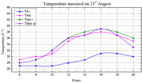
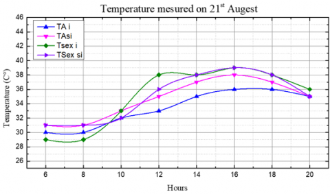
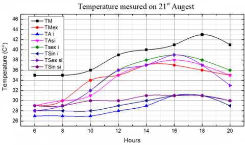
Temperature Results Measured on August 21
August 21
A
B
C
D
Figure 11. Temperatures measured on August 21
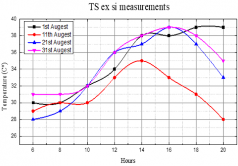
The surface temperature of prototype B (with insulation) (See Figure 11A) is 28° and reaches its maximum (31°) at 4 pm throughout the day, it is just one degree warmer than room temperature, and between 5 and 7 pm, it stabilizes at 30 degrees. There is a decrease of 2° to 3° between the ambient temperature with insulation (prototype B) and the ambient temperature of prototype A (See Figure 11B) (without insulation).
The two prototypes' surface temperatures follow the same trajectory as the surface temperature with insulation (see Figure 11C), with a 1° reduction between 12 and 2 pm and a 3° to 4° decrease between 6 and 8 pm. The ambient temperature without insulation (A) follows the curve of the surface temperature with or without insulation with a drop of only 1°; meanwhile, the ambient temperature with insulation (B) drops 5° to 6°, reaching 28° (minimum temperature) and 29° (maximum), and the ambient temperature without insulation (A) drops 3° to 4°, attaining 27° (minimum) and 30° (maximum) (See Figure 11D).
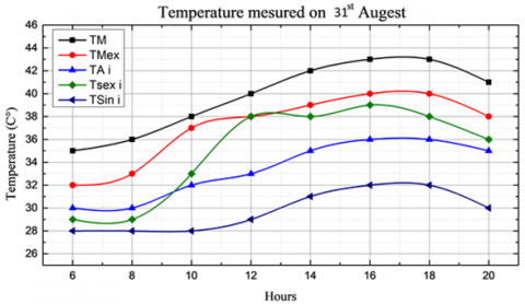
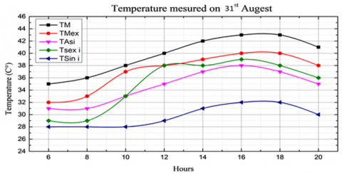
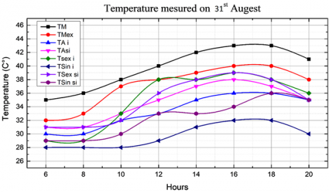
Temperatures measured on August 31
August 31
A
B
C
D
Figure 12. Temperatures measured on August 31
• The ambient and surface temperatures of prototype B (with insulation) are much lower by 3° to 4° than those of the outside (average temperature TM and average outside temperature measured) (See Figure 12A).
• One difference noticed on this day, unlike the others, is that the interior surface temperature (prototype B) is 2° below ambient temperature (B).
• The ambient temperature without insulation (A) (See fig 12 B, C). Varies between 30° and 38° and is 3° to 4° lower than that measured outside.
• We also notice that there is a difference of two degrees between the ambient temperature (A) and (B), which varies between 30° and 32° (the minimum) and 36° to 38° (the maximum) (See Figure 12D), whereas there is no difference between the outside surface temperature curve without insulation and the ambient temperature without insulation.
The days corresponding to August 1, 11, and 21 are manifestly close, with ambient temperatures ranging from 26 degrees Celsius at 6 am to 34 degrees Celsius at 6 pm (See Figure 13). Ambient temperatures for Prototype B (with insulation) on August 31 are significantly higher by 4℃ in the morning and 5℃ in the afternoon (see Figure 14). Unlike earlier observations, where each day has a considerably distinct curve, August 1 has the lowest curve, followed by August 11, August 11, August 21, and finally August 31 (see Figure 14).
Figure 13. Ambient temperature with insulation (prototype B)
Figure 14. Ambient temperature without insulation (prototype A)
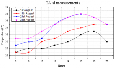
The interior surface temperatures of prototype B of 11 are the lowest, and they are 3℃ more deficient than those of (1/21/31). (See Figure 15). These temperatures taken on August 1, 21, and 31 are the same in the morning but differ by 1 degree Celsius at lunchtime. The temperature dropped by 1 degree Celsius on August 1 compared to August 11 and 21. (See Figure 16) There is a large discrepancy on August 11 and other days, with a difference of 3 to 4 degrees on the 31st and the day when we had the highest temperatures, which reached 36 degrees.
Figure 15. Interior surface temperature with insulation (prototype B) south facade
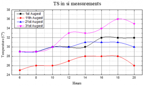
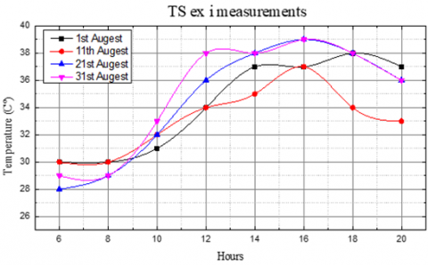
The outer surface temperature on August 11 was (see Figure 17). The highest temperature was recorded around 2:00 pm. The temperature decreased to 28 degrees at 8 pm due to the afternoon rain, compared to previous days when the highest temperature was 39 degrees between 4 and 6 pm. Except for the 11th, which has seen a 3° drop in temperature compared to the previous days, all of the temperatures follow the same trend. The external surface temperatures on prototype B (see Figure 18) are practically identical in the morning (6 am to 12 pm), with a difference of 1°, but in the afternoon, a clear distinction was recorded, with the lowest being 11 and the highest being 12.
Figure 16. Outdoor surface temperature without insulation (prototype A) southern facade
Figure 17. Outside surface temperature without insulation (prototype A) southern facade
Figure 18. Outside surface temperature with insulation (prototype B) south facade
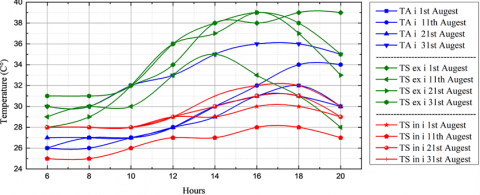
There are three main temperature groups here: the surface temperatures are lower than the ambient temperatures by a difference of 2 to 5 degrees Celsius. The ambient temperatures range between 2℃ and 6℃ compared to the external surface temperatures (see Figure 19).
Figure 19. Internal and external surface temperature and the ambient temperature of the four days tested
3.2 Results of simulation
Simulated model:
The simulation under TRNSYS © was carried out through the use of the single-zone type (see Figure 20)., the orientation is the same as that chosen for the experiment (south), the climatic file of the city under study was generated by the software Metéonorm V7.2 © for type15-2 Weather Data.
Three models (see Table 8) were simulated to optimize the use of this material according to the following table (see Table 9).
Figure 20. Simulated model
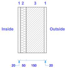
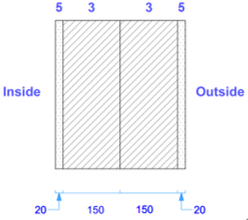
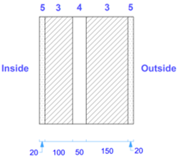
Table 8. Description of the wall combination for each prototype for simulation
|
Prototype |
Description |
Composition |
|
Prototype 1 (The prototype B of the experiment) |
a wall made up of a single row of bricks (35/10/15 cm) with a 5 cm straw insulation layer and a 2 cm clay plaster |
|
|
Prototype 2 |
Double-wall glued without air gap. 2 cm cement plaster. |
|
|
Prototype 3 |
Double-wall with 5 cm air gap and 2 cm cement plaster. |
|
|
1: Clay plaster 2: Straw insulation 3: Row of CSEB 4: Air gap 5: Cement plaster |
||
For the windows, the choice is made on the model Mdv_bg double glazing low emissivity with gas U = 1.43 W / m3.k n ° = 4 for prototypes (2/3).
The simulation was launched during August (with a time step of one hour) the results were exported in (Xls) format. Subsequently, the graphs were developed by the ORIGIN © program during August (5088.0-58320). The four days selected during this period (11/01/21/31) correspond to the times of the year (5088.0 / 5336.0 / 5584.0 / 58320).
Table 9. Description of the other components of the prototypes 2/3
|
For the windows, the choice is made on the model Mdv_bg double glazing low emissivity with gas U = 1.43 W / m3.k n ° = 4 for prototypes (2/3) |
|||||||||
|
N° |
Description |
U-value |
g- value |
||||||
|
1 |
2001 |
Double |
2.95 |
0.777 |
|||||
|
2 |
3001 |
Triple |
2 |
0.7 |
|||||
|
3 |
4001 |
Double-low-e |
1.76 |
0.544 |
|||||
|
4 |
5001 |
Double low.ar |
1.43 |
0.544 |
|||||
|
For the ceiling only one type for the 2 prototypes (2/3) |
For the slab only type for the 2 prototypes (2/3) |
||||||||
|
N° |
Layer |
thickness |
Type |
N° |
Layer |
thickness |
Type |
||
|
1 |
plaster |
0.020 |
massive |
1 |
floor tile |
0.020 |
massive |
||
|
2 |
hollow body |
0.160 |
massive |
2 |
Cement Mortar |
0.020 |
massive |
||
|
3 |
Slab_composition |
0.040 |
massive |
3 |
Floating slab |
0.100 |
massive |
||
|
4 |
Screed |
0.100 |
massive |
4 |
Bristling |
0.300 |
massive |
||
-Prototype 1:
Figure 21. Ambient temperature and energy needs during August of prototype 1
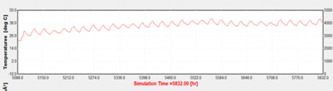
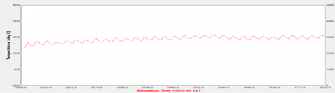
Prototype 1 (see Figure 21), which outer wall is made up of a single row of bricks (35/10/15 cm) with a 5 cm straw insulation layer and 2 cm clay-based plaster, corresponds to the prototype B of the experiment. On August 1 (5088.00h), the ambient temperature is 30℃, on the 11th (5336.0h) it is 35℃, on the 21st (5584.0h) 32℃ and on the 31 (5832.0h) it is 38℃. Which gives an average temperature of 33.75℃.
- Prototype 2:
Figure 22. Ambient temperature and energy needs during August of prototype 2
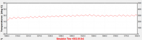
Prototype 2 (see Figure 22), the exterior wall of which is made up of a double row of bricks glued without air gap and coated with 02 cm of cement, exhibits on August 1 (5088.00h) an ambient temperature of 25℃, on 11 (5336.0 h) a temperature of 28℃, on the 21st (5584.0h) at 31℃ and on the 31 (5832.0h) at 33℃. Which gives an average temperature of 29.25℃.
- Prototype 3
Figure 23. Ambient temperature and energy needs during August of prototype 3
Prototype 3 (see Figure 23), whose outside wall is made up of a double row of bricks with an air gap of 05 cm and is coated with 02 cm of cement, has an ambient temperature of 21℃ on August 1 (5088.00h), 27℃ on the 11 (5336.0h), 28.5℃ on the 21 (5584.0h), and 30℃ on the 31 (5832.0h). which gives an average temperature of 33.75 degrees Celsius.
A concordance between the measured (experiment) and simulated ambient temperatures (see Figure 24). It was recorded on August 31 (37℃), while a difference of 2℃ between the measured temperature and that simulated was observed on August 1. On the other hand, for the days of August 11 and 21, the difference increases to reach 5℃. Finally, a difference of only 1℃ was recorded on August 1.
To estimate the energy needs (see Figure 25), a temperature threshold was determined for the operation of residential buildings, 23℃ to 26℃ for air conditioning (see Figure 25B). This interval is located in the thermal comfort zone of the standard (NF EN 15251), which gives temperature ranges depending on the type of construction.
Figure 24. Ambient temperature and internal surface temperatures of the four days tested
A
B
Figure 25. 4 days energy needs tested and ambient temperature
The least important energy needs (see Figure 25A) for air conditioning are those of prototype 3 (Double wall with 5 cm air gap and 2 cm cement plaster) with values that vary between (2100.00 / 2700.00 / 2950.00 /3000.00 KJ / H) which corresponds to hours (5088.00 / 5336.0 / 5584.0 / 5832.0h) and days (1/11/21/31 August). As a result, the findings produced are precise in terms of material optimization with various combinations. The energy required by the double-wall with an air gap is the least, followed by the energy needed for the double-wall without an air gap (prototype2). Following that is the third prototype, which is identical to the last prototype (prototype B of the experiment). Prototype 3 on the day of the 21st is located in the thermal comfort zone of the standard (NF EN 15251) while it has acceptable comfort (less than 26℃) on the 11th (see Figure 25B).
The experimental investigation, which was carried out through the manufacture of two prototypes on a smaller scale, allowed some parameters on the thermal functioning of the wall formed of compressed and stabilized earth brick to be tested (external surface temperature, ambient temperature, internal surface temperature). These prototypes allowed researchers to establish the real effects of SCEB's thermal qualities. The results show that this material improves thermal wall performance and, as a result, internal thermal comfort; surface temperature is reduced by 7℃, influencing stored heat and heat flow—transferred to the interior, lowering the internal temperature to 6℃ and, as a result, lowering the ambient temperature by 5℃. Numerical simulation was performed on the prototypes to optimize the impact of a few parameters such as absorption factor, heat transmission, and measuring energy consumption. In this part of the work, a digital model was developed with a combination of three types of walls; the results showed that the mastery of building elements such as the material directly impacts the thermal and energy efficiency of the construction. The optimization of a single parameter (ambient temperature) is insufficient and requires the improvement of a few parameters (ventilation and relative humidity), so attention must be paid to the different components of the facade, such as reflective paint, to decrease heat absorption.
The simulation and the experimentation have demonstrated the ability of a BTSC brick wall to reduce the external and internal surface temperatures of the walls up to 8℃; subsequently, it influences the ambient temperature, with the decrease of 5℃ to 8℃. The model has reduced the air conditioning energy requirements to 4000.00 kJ / h (highest value) and 2100.00 kJ / h (lowest value) (minimum value). The thermal behaviour of BTSC, and earth-based material suited for arid and semi-arid locations, was determined to be positive in this study.
As a result, it is an appropriate option of long-lasting and low-cost building materials for lowering energy consumption due to air conditioning, avoiding the hot wall effect in the summer, and guaranteeing adequate thermal comfort. Building materials, in this case SCEB, have a significant influence on the energy efficiency of a building, their well thought out use for better optimization for hot and arid climates can ensure the desired thermal comfort and establish a balance between passive and active solutions. The value of a material's thermal transmittance is a determining factor in ensuring a wall's thermal performance.
These compressed and stabilized earth bricks have constructive and technical advantages, such as the manufacture of homogeneous and regular bricks with the capacity to carry out technical controls. In addition, its high density gives a valuable quality of thermal inertia for heat storage and thermal regulation. They are also fire resistant (earth-based). As these bricks are not fired, raw earth requires little energy to manufacture and generates minimal CO2 emissions, making it a healthy and non-polluting material. These earthen bricks have no harmful health effects because they may be made from locally accessible earth, with significant environmental benefits. This material's mass production at low cost provides jobs and promotes the economy of the region. Finally, these bricks serve to recreate the region's identity by enhancing traditional knowledge and providing architectural cohesion.
|
IPCC |
Intergovernmental Panel on Climate Change |
|
OECD |
Organization for Economic Co-operation and Development |
|
WEF |
World Economic Forum |
|
ETI |
Energy transition index |
|
CRATerre |
(in French) the international center for earthen architecture |
|
CNERIB |
(in French) National Center for Integrated Building Studies and Research |
|
Enerdata |
(in French) an economic research office specializing in the energy sector and its interactions with the environment |
|
IEQ |
Indoor environmental quality |
|
CEC |
Compressed earth concrete |
|
SEC |
Stabilized earth concrete |
|
CSEB |
Compressed and stabilized earth brick |
|
RTD |
Regulatory Technical Document |
|
NF P 94 051 |
Standard intended for determining the two Atterberg limits (liquidity limit at the cup and plasticity limit of the roll) |
|
NF EN 15251 |
Standard of indoor environment criteria for the design and evaluation of the energy performance of buildings. |
|
XP P13-901 |
standards related to compressed earth blocks for walls and partitions |
|
NFP 18-404 |
technical standards for concrete and concrete products |
|
ASHRAE |
American Society of Heating, Refrigerating, and Air Conditioning Engineers |
|
TM |
Average temperature |
|
TMex |
Measured outside temperature |
|
TA I |
Ambient temperature with insulation (prototype B) |
|
TAsi |
Ambient temperature without insulation (prototype A) |
|
TSex i |
Outdoor surface temperature with insulation (prototype B) south façade |
|
TSin I |
Indoor surface temperature with insulation (prototype B) south façade |
|
TSex si |
Outdoor surface temperature without insulation (prototype A) south façade |
|
TSin si |
Outdoor surface temperature without insulation (prototype A) south façade |
|
CRS |
cement resistant to sulphates |
|
CM PA |
construction materials production agency |
|
TRS |
operating temperature or the resulting dry temperature |
|
App D |
apparent density |
|
Abs D |
Absolute density |
|
FM |
Fineness modulus |
|
SE |
Send equivalent |
[1] Besancenot, J. (2007). Health and climate change, rising concerns. Delachaux Et Niestle. p. 48. (In French). https://www.sudoc.fr/11927051X.
[2] Chan, C.F., Lebedeva, J., Otero, J., Richardson, G. (2008). Urban heat islands: A climate change adaptation strategy for Montreal. Plan Canada, 48(1): 30.
[3] Morel, J.C., Charef, R., Hamard, E., Fabbri, A., Beckett, C., Bui, Q.B. (2021). Earth as construction material in the circular economy context: Practitioner perspectives on barriers to overcome. Philosophical Transactions of the Royal Society B, 376(1834): 20200182. https://doi.org/10.1098/rstb.2020.0182
[4] CNERIB (1998). DTR C3-2 Document, Ministry of Housing and Town Planning, Thermal Regulations for Residential Buildings - Calculation Rules for Heat Loss. booklet 1: 4, 58. (In French). https://www.academia.edu/11791860/DTR_C3_2_Reglement_thermique_des_batiments_dhabitation_regle_de_calcul_des_peperdition_calorifique_FACICULE1.
[5] Mahamat, S. (2010). comparative study between the improvement of compressed earth bricks stabilized by cement and slaked lime. p. 34, 78. (In French). https://fr.scribd.com/document/458314883/Memoire-Mahamat-Saleh.
[6] Hailu, H., Gelan, E., Girma, Y. (2021). Indoor thermal comfort analysis: A case study of modern and traditional buildings in hot-arid climatic region of Ethiopia. Urban Science. 5(3): 53. https://doi.org/10.3390/urbansci5030053
[7] Fabbri, A., Morel, J.C., Gallipoli, D. (2018). Assessing the performance of earth building materials: A review of recent developments. RILEM Technical Letters, 3: 46-58. https://doi.org/10.21809/rilemtechlett.2018.71
[8] Ameur, O., Dich, Z. (2017). Earth material: Study of shear résistance and removal. p. 11, 18. (In French). http://dspace.univ-tlemcen.dz/bitstream/112/10427/1/Ms.Gc.Ameur%.
[9] Rojat, F., E. Hamard, A. Fabbri, B. Carnus, F. McGregor (2020). Towards an easy decision tool to assess soil suitability for earth building. Construction and Building Materials, 257: 119544.
[10] Quang, T.N., He, C.R., Knibbs, L.D., De Dear, R., Morawska, L. (2014). Co-optimisation of indoor environmental quality and energy consumption within urban office buildings. Energy and Buildings, 85: 225-234. https://doi.org/10.1016/j.enbuild.2014.09.021
[11] Catalina, T., Iordache, V. (2012). IEQ assessment on schools in the design stage. Building and Environment, 49: 129-140. https://doi.org/10.1016/j.buildenv.2011.09.014
[12] Katafygiotou, M., Serghides, D.K. (2015). Bioclimatic chart analysis in three climate zones in Cyprus. Indoor and Built Environment, 24(6): 746-760. https://doi.org/10.1177/1420326X14526909
[13] Achard, P., Gicquel, R. (1986). European Passive SolarHandbook: Basic Principles and Concepts for PassiveSolar Architecture: Preliminary Edition: Commission ofthe European Communities. D.G. XII CEE.
[14] Frontczak, M., Wargocki, P. (2011). Literature survey on how different factors influence human comfort in indoor environments. Building and Environment, 46(4): 922-937. https://doi.org/10.1016/j.buildenv.2010.10.021
[15] Rocca, M. (2017). Health and well-being in indoor work environments: A review of literature. In 2017 IEEE International Conference on Environment and Electrical Engineering and 2017 IEEE Industrial and Commercial Power Systems Europe (EEEIC/I&CPS Europe). https://doi.org/10.1109/EEEIC.2017.7977516
[16] Standard, A. (2010). Standard 55-2010. Thermal Environmental Conditions for Human Occupancy. Atlanta: American Society of Heating, Refrigerating and Air-Conditioning Engineers. Inc.
[17] CRATerre (1991). The Basic Elements Compressed Earth Block. (In French). http://www.craterre.org/terre.grenoble.archi.fr/documentation/downloads/BTC-Elementsdebase.pdf.
[18] Houben, H., Guillaud, H. (1994). Earth construction. A comprehensive guide: IntermediateTechnology Publications. (In French).
[19] Abbou, M., Semcha, A., Kazi-Aoual, F. (2020). Stabilization of compressed earth block clayey materials from Adrar (Algeria) by lime and crushed sand. Journal of Building Materials and Structures, 7(1): 42-50. https://doi.org/10.5281/zenodo.3744137
[20] Mango-Itulamya, L.A., Collin, F., Pilate, P., Courtejoie, F., Fagel, N. (2019). Evaluation of Belgian clays for manufacturing compressed earth blocks. Geologica Belgica, 22(3-4). https://doi.org/10.20341/gb.2019.002
[21] Taallah, B. (2014). Study of the Physicomcanic behavior of the compressed earth block with fibers. Mohamed Khider Biskra University. (In French). http://thesis.univ-biskra.dz/1173/.
[22] Taallah, B., Guettala, A. (2016). The mechanical and physical properties of compressed earth block stabilized with lime and filled with untreated and alkali-treated date palm fibers. Construction and Building Materials, 104: 52-62. https://doi.org/10.1016/j.conbuildmat.2015.12.007
[23] Doat, P.A.H., Hugo Houben, Silvia Matuk, François Vitoux (1979). build in earth: CRAterre, Collection AnArchitecture. (In French).
[24] Houben, H., Guillaud, H. (2006). CRATerre: Earth Construction Treaty. Éditions Parenthèses: Marseille, France: p. 101,102. (In French).
[25] Vénuat, M. (1980). Lime and cement soil treatment. p. 459.
[26] Kujala, K. (1996). Effect of humus on the binding reaction in stabilized soils. Grouting and deep mixing, p. 415-419.
[27] Abdelhamid, H. (2019). Contribution to the productionof compressed and fiber-reinforced earth blocks.Universit Mohamed Boudhiaf-M'Sila. (In French). http://dspace.univ-msila.dz:8080//xmlui/handle/123456789/16096.
[28] Tremblay, H. (1998). Mechanical improvement .and prediction of the compressibility of fine soils in Quebec [PhD thesis]. Québec: Université de Laval: p. 257. (In French). http://hdl.handle.net/20.500.11794/41889.
[29] Guettala, A. (2003). Stabilized earth concrete: improving its durability in water. phd thesis, University of Biskra. (In French).
[30] Vilenkina, N. (1956). Use of soil material in the construction of rural buildings. Mouscou. (In Russian).
[31] Bogue, R.H. (1955). The chemistry of Portland cement. Vol. 79. LWW.