Xuejing Cheng | Qian Cong*
© 2026 The authors. This article is published by IIETA and is licensed under the CC BY 4.0 license (http://creativecommons.org/licenses/by/4.0/).
OPEN ACCESS
Surface texturing can modify lubricant transport at sliding interfaces and thereby influence the durability of reciprocating mechanical components. This study investigates the hydrodynamic lubrication and wear mechanisms of a surface-textured piston used in an F-1300 drilling mud pump. Regularly arranged pits were introduced on the surface of the polyurethane piston cup, with pit diameter, angular parameter, and depth considered as the principal geometric parameters. The effects of the texture geometry on the maximum friction stress were first evaluated, followed by field tests comparing the service lives and wear characteristics of textured and conventional pistons. Computational fluid dynamics (CFD) simulations using CFX were then performed to examine the lubricant pressure distribution and flow behavior at the piston surface. The results show that surface texturing alters the local mechanical stress state while producing a pronounced redistribution of the lubricant flow. Compared with the conventional piston, the textured surface generates localized pressure variations around the pits and promotes lubricant retention through flow deceleration and recirculation within the textured regions. The pits also provide storage space for lubricant and entrained wear particles, which limits severe direct interaction at the piston–liner interface. Field tests confirm the practical effect of this mechanism: the service life of the selected textured piston increased from 271 h to 370 h, corresponding to an improvement of 36.53%. The results indicate that piston surface texturing involves a trade-off between local stress concentration and favorable hydrodynamic lubrication. Appropriate control of the texture geometry can therefore improve lubricant-film behavior and extend piston durability under demanding mud-pump operating conditions.
surface texturing, mud pump piston, hydrodynamic lubrication, lubricant flow, computational fluid dynamics, wear resistance
Mud pumps are critical components of drilling systems, where the piston–liner assembly operates under high pressure, repeated reciprocating motion, and continuous exposure to abrasive drilling fluids. The piston cup is particularly susceptible to deterioration because its surface is subjected simultaneously to cyclic mechanical loading, sliding contact, lubricant loss, and intrusion of solid particles. Once the lubricating film between the piston and cylinder liner becomes insufficient, direct or near-direct contact can accelerate surface damage and eventually cause sealing failure. Improving the lubrication state of this interface is therefore important for maintaining the operational reliability and service life of mud-pump pistons.
Surface texturing provides a passive means of regulating fluid behavior at lubricated sliding interfaces. Unlike a nominally smooth surface, a textured surface contains deliberately introduced micro- or mesoscale features that locally modify the geometry of the lubricant film. Recent studies have shown that appropriately designed dimples and related surface features can modify hydrodynamic pressure generation, lubricant transport, friction, and wear under lubricated sliding conditions [1-4]. The resulting tribological response depends strongly on texture dimensions and spatial distribution. In particular, variations in dimple diameter, depth, density, and arrangement can substantially alter hydrodynamic lubrication performance [1]. Studies of reciprocating piston ring–liner contacts have likewise demonstrated that the effectiveness of surface texturing depends on the geometry and location of the textured regions as well as the operating conditions [2, 3]. Surface texture should therefore be regarded as a functional component of the lubricated interface rather than simply as a geometric modification.
The fluid-dynamic mechanisms associated with surface textures have consequently received considerable attention. Recent numerical and Computational fluid dynamics (CFD)-based investigations have shown that surface cavities can modify both pressure and velocity distributions within lubricated contacts [4-6]. As lubricant passes across a textured region, the local change in surface geometry disturbs the original flow path and produces a redistribution of pressure around the cavity. Lubricant entering the textured region may also undergo flow deceleration and local recirculation, thereby changing its residence within the contact. The magnitude of these effects depends on texture depth, diameter, distribution, and relative surface motion [4-6]. Recent theoretical and experimental studies have further established a close relationship between the local flow field generated by surface textures and the resulting macroscopic lubrication performance [6]. These findings also indicate that excessive or poorly configured texturing does not necessarily produce a favorable response, since changes in local contact and flow conditions may offset part of the hydrodynamic effect.
Reciprocating piston–liner systems are particularly relevant to this problem because the direction and velocity of sliding vary continuously during operation. Recent investigations of textured cylinder liners and piston rings have shown that surface features can modify lubricant distribution, oil-film behavior, friction, and wear under reciprocating conditions [2, 3, 7-9]. Experimental studies have further demonstrated that texture geometry and location play an important role in determining the tribological response of the piston ring–liner interface [8]. In addition to influencing lubricant-film formation, appropriately designed surface cavities can provide temporary storage space for lubricant and entrained particles. Numerical studies of textured piston ring–cylinder liner systems have similarly shown that the interaction between surface geometry and lubricant transport governs the resulting frictional and lubrication behavior [9].
Lubricant retention becomes particularly important when the lubricant supply is limited or periodically disrupted. Recent studies under starved lubrication have shown that appropriately configured surface textures can promote lubricant transport into the contact region and provide local oil-storage capacity [5, 10, 11]. Lubricant retained within surface cavities can remain available near the sliding interface when the surrounding lubricant supply decreases. Surface dimples can also provide accommodation space for wear debris or abrasive particles, thereby reducing their continuous interaction with the principal sliding surfaces [8, 12]. At the same time, parameterized studies of textured piston ring–liner contacts have demonstrated that changes in pit dimensions can significantly affect frictional and lubrication characteristics [13]. These observations suggest that the performance of a textured surface results from a balance among hydrodynamic pressure redistribution, lubricant retention, particle accommodation, and the mechanical response introduced by the surface geometry.
Despite these advances, most recent investigations of textured reciprocating contacts have concentrated on engine piston rings, cylinder liners, bearings, seals, or laboratory tribological specimens. The lubrication mechanism of a textured mud-pump piston differs in several respects. The piston cup is a deformable component operating under severe reciprocating conditions, while lubricant depletion and the ingress of mud and wear particles can occur simultaneously. In addition, improvements observed in numerical lubrication characteristics need to be connected with actual component durability under field operating conditions. The relationship among texture geometry, local stress, lubricant-pressure and flow redistribution, particle retention, and long-term piston service life therefore remains insufficiently understood for this application.
To address this problem, the present study investigates the hydrodynamic lubrication and wear mechanisms of a surface-textured F-1300 mud-pump piston through numerical analysis and field testing. Regularly arranged pits are introduced on the piston-cup surface, and the effects of pit diameter, angular parameter, and depth on the mechanical response are first examined. CFD simulations are then used to compare the lubricant-pressure distribution and flow characteristics of conventional and textured piston surfaces, with particular attention to local pressure redistribution, flow deceleration, recirculation, and lubricant retention around the pits. Finally, field tests and post-service wear observations are used to determine whether the mechanisms identified numerically are reflected in actual piston durability. The study therefore links texture geometry, lubricant-flow behavior, surface wear, and field service life within a unified framework for the design of surface-textured mud-pump pistons.
2.1 Mud pump piston and operating configuration
The investigated component is the piston assembly of an F-1300 drilling mud pump. During operation, the piston reciprocates inside the cylinder liner and provides the pressure required for drilling-fluid circulation. The piston cup is the principal sealing and sliding component and consists of a polyurethane rubber lip supported by a nylon root. The outer surface of the cup remains in close contact with the inner wall of the cylinder liner during reciprocating motion.
The piston–liner interface operates under repeated sliding and severe loading conditions. Lubricant present at the interface forms a film between the piston cup and the cylinder liner and reduces direct surface interaction. During continuous reciprocating motion, however, part of the lubricant can be displaced from the contact region. Drilling mud and solid particles may also enter the interface. The resulting deterioration of the lubrication condition increases the likelihood of scratching, local material removal, and damage near the rubber–nylon junction. These processes progressively impair the sealing capability of the piston and ultimately determine its service life.
A conventional piston has a nominally smooth cup surface and therefore provides limited additional space for lubricant and entrained particles. In the present design, regularly distributed surface pits were introduced into the polyurethane cup to modify the local lubricant-flow environment. The pits were intended to influence lubricant transport and retention during reciprocating sliding while providing additional space for entrained wear particles. The conventional piston and the surface-textured piston were subsequently compared in terms of mechanical response, lubricant-flow characteristics, wear morphology, and field service life.
2.2 Bionic surface-texture geometry
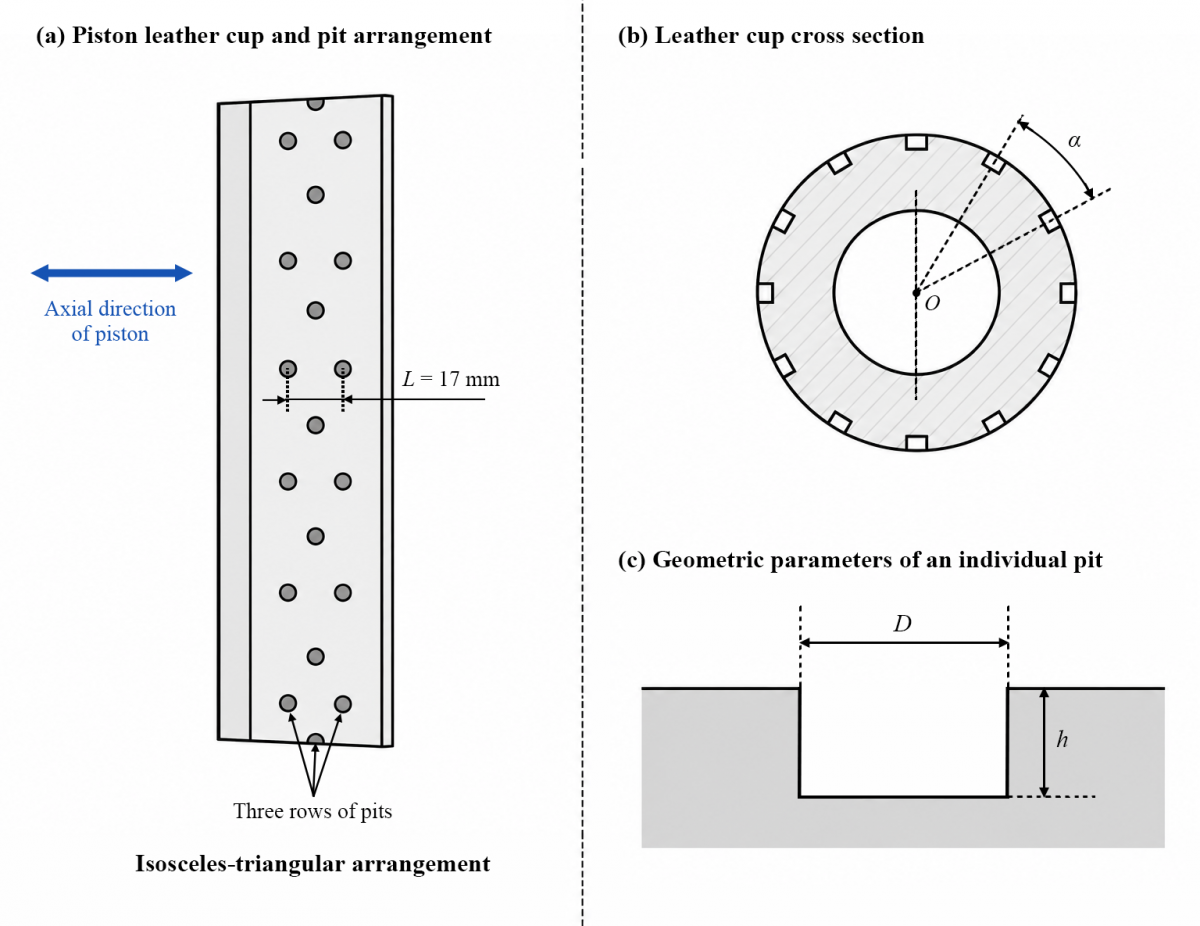
The surface texture was designed as a regular array of discrete pits machined into the outer surface of the polyurethane piston cup. Three geometric parameters were considered: pit diameter (D), angular parameter (α), and pit depth (h). The pits were distributed in an isosceles-triangular arrangement and arranged in three rows along the axial direction of the piston. The center-to-center spacing between adjacent pits was maintained at L = 17 mm for all textured configurations. The piston-cup configuration and the principal geometric parameters of the surface pits are illustrated schematically in Figure 1. The pit diameter controls the lateral extent of each textured region and therefore the area over which the lubricant flow interacts with the surface feature. The pit depth determines the available cavity volume for lubricant and entrained particles. The angular parameter characterizes the circumferential positioning of the pits and can consequently influence the spatial distribution of the textured regions around the piston surface. These three parameters were varied while the pit spacing and arrangement were kept unchanged, allowing the effects associated with texture geometry to be evaluated under a consistent surface layout.
The textured piston cups were manufactured using a CNC machining center. After machining, residual debris was removed from the pits before assembly and testing. The same basic piston configuration was retained for all cases so that the principal difference between the conventional and textured pistons was the presence and geometry of the surface pits.
The surface texture was not assumed to provide an exclusively favorable mechanical response. Increasing the dimensions of the pits removes material from the cup surface and can alter the local stress state of the piston. At the same time, the cavities modify lubricant transport along the piston–liner interface. The performance of the textured piston therefore depends on the balance between the mechanical influence of the texture and its effect on hydrodynamic lubrication. This coupled consideration forms the basis for the numerical and experimental analyses presented in the following sections.
Figure 1. Geometry of the surface-textured mud-pump piston: (a) piston cup and pit arrangement; (b) cross-sectional configuration and angular parameter; (c) geometric parameters of an individual pit
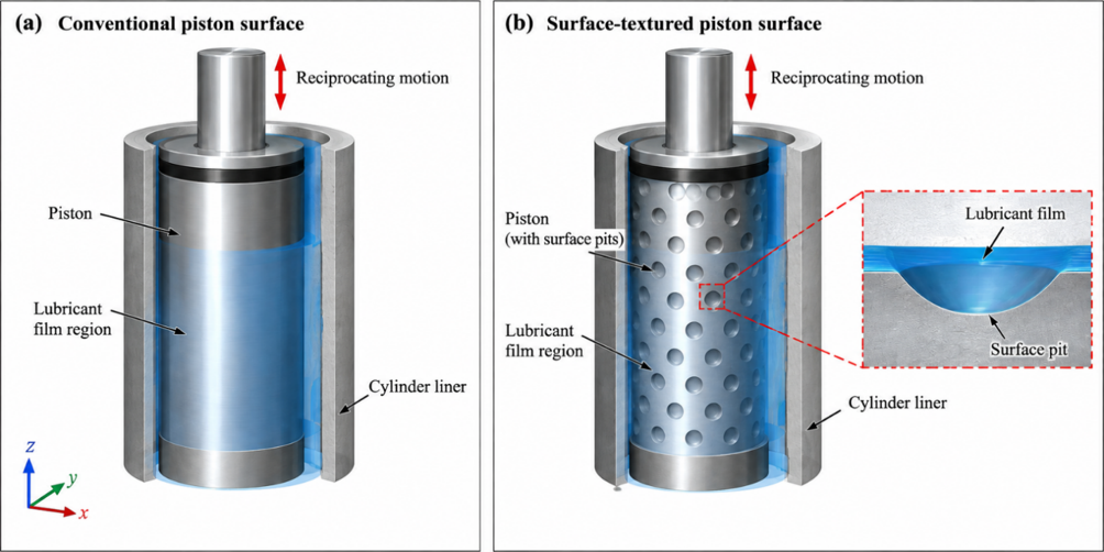
Figure 2. Schematic representation of the computational domain for lubricant-flow analysis at the piston–liner interface: (a) conventional piston surface; (b) surface-textured piston surface
3.1 Computational model
Numerical analysis was performed to examine the mechanical response of the piston and the lubricant-flow characteristics at the piston–liner interface. The computational geometry was established according to the F-1300 mud-pump piston described in Section 2. Particular attention was given to the region adjacent to the piston-cup surface, where the surface pits directly disturb lubricant transport during relative motion between the piston and cylinder liner.
A schematic representation of the computational domain is shown in Figure 2. Figure 2(a) represents the conventional piston–liner configuration, consisting of the cylinder liner, lubricant-film region, and nominally smooth piston surface. Figure 2(b) shows the corresponding surface-textured configuration, in which regularly arranged pits are introduced into the piston surface. The enlarged view in Figure 2(b) illustrates the local lubricant region associated with an individual surface pit. Relative reciprocating motion between the piston and cylinder liner drives lubricant through the interfacial region. The conventional and textured configurations were evaluated under equivalent numerical conditions so that differences in the calculated pressure and flow fields could be attributed primarily to the presence of the surface texture.
The numerical investigation consisted of two complementary parts. First, the mechanical response of different texture geometries was evaluated using the maximum friction stress on the piston surface as the principal indicator. Second, the lubricant flow around the conventional and textured surfaces was examined using CFX. The fluid-dynamic analysis focused on the spatial distribution of lubricant pressure and the modification of local flow trajectories caused by the surface pits. These numerical results were subsequently interpreted together with the field service-life tests and post-service wear observations.
3.2 Governing equations
The lubricant-flow calculation was formulated on the basis of the conservation of mass and momentum. The general continuity equation is expressed as:
$\frac{\partial \rho}{\partial t}+\nabla \cdot(\rho u)=0$ (1)
where, $\rho$ is the lubricant density, $t$ is time, and $u$ is the velocity vector.
For an incompressible lubricant with constant density, Eq. (1) reduces to:
$\nabla \cdot \mathrm{u}=0$ (2)
The conservation of momentum is described by the Navier–Stokes equation:
$\frac{\partial(\rho \mathrm{u})}{\partial t}+\nabla \cdot(\rho \mathrm{u} \otimes \mathrm{u})=-\nabla p+\nabla \cdot \tau+\mathrm{S}_M$ (3)
where, $p$ is the static pressure, $\tau$ is the viscous stress tensor, and $\mathrm{S}_M$ denotes the momentum source term.
For a Newtonian fluid, the viscous stress tensor is given by:
$\tau=\mu\left[\nabla \mathrm{u}+(\nabla \mathrm{u})^T-\frac{2}{3}(\nabla \cdot \mathrm{u}) \mathrm{I}\right]$ (4)
where, $\mu$ is the dynamic viscosity and $I$ is the identity tensor. Under the incompressibility condition given by Eq. (2), $\nabla \cdot \mathrm{u}=0$ and Eq. (4) can therefore be simplified to:
$\tau=\mu \left[\nabla \mathrm{u}+(\nabla \mathrm{u})^T\right]$ (5)
Accordingly, the momentum equation for an incompressible Newtonian lubricant can be written as:
$\rho\left(\frac{\partial \mathrm{u}}{\partial t}+\mathrm{u} \cdot \nabla \mathrm{u}\right)=-\nabla p+\mu \nabla^2 \mathrm{u}+\mathrm{S}_M$ (6)
The governing equations were solved in CFX to obtain the lubricant pressure and velocity fields within the piston–liner interface. The numerical analysis focused on the hydrodynamic response induced by the surface pits, particularly the redistribution of local pressure and the modification of lubricant-flow trajectories around the textured regions. The calculated pressure and flow fields were subsequently used to interpret the lubrication mechanism of the surface-textured piston.
3.3 Boundary conditions and numerical procedure
The numerical domain represented the lubricant region adjacent to the piston surface and the corresponding cylinder-liner boundary. Relative motion between the piston surface and the cylinder liner reproduced the sliding condition occurring during mud-pump operation. The conventional and textured configurations were evaluated under equivalent numerical conditions to permit direct comparison of their pressure and flow characteristics.
The governing conservation equations were solved using CFX with a finite-volume-based numerical formulation. Pressure and velocity fields were obtained throughout the lubricant domain, and the solutions were post-processed to identify differences between the conventional and textured piston surfaces. Particular attention was paid to the regions immediately upstream of, inside, and downstream of the pits because these locations govern the local redistribution of lubricant.
The numerical analysis was primarily intended for comparative assessment of the conventional and textured piston configurations under identical computational conditions. Accordingly, the discussion focuses on relative changes in lubricant-pressure distribution and flow structure rather than on absolute prediction of the complete lubrication state.
3.4 Surface-texture cases
The effects of texture geometry were investigated using nine combinations of pit diameter (D), angular parameter (α), and pit depth (h). A conventional piston without surface pits was used as the reference case. The center-to-center pit spacing was maintained at L = 17 mm for all textured cases. The investigated configurations and corresponding maximum friction stresses are summarized in Table 1.
Among the textured configurations, Case 2 produced the lowest maximum friction stress 3.1180 MPa, whereas Case 8 produced the highest value 4.6384 MPa. Their increases relative to the conventional piston were 65.98% and 146.92%, respectively. These two cases therefore represent contrasting mechanical responses and were selected for subsequent field comparison together with the conventional piston.
Table 1. Surface-texture configurations and calculated maximum friction stress
|
Case |
D (mm) |
α (°) |
h (mm) |
Maximum Friction Stress (MPa) |
Change Relative to Conventional Piston (%) |
|
Reference |
0 |
0 |
0 |
1.8785 |
– |
|
1 |
1.5 |
10 |
2 |
4.0518 |
115.69 |
|
2 |
1.5 |
15 |
4 |
3.1180 |
65.98 |
|
3 |
1.5 |
20 |
6 |
3.6290 |
93.19 |
|
4 |
3.0 |
10 |
4 |
4.6011 |
144.93 |
|
5 |
3.0 |
15 |
6 |
3.9840 |
112.08 |
|
6 |
3.0 |
20 |
2 |
3.8618 |
105.58 |
|
7 |
4.5 |
10 |
6 |
4.0857 |
117.50 |
|
8 |
4.5 |
15 |
2 |
4.6384 |
146.92 |
|
9 |
4.5 |
20 |
4 |
3.9089 |
108.09 |
It should be emphasized that a higher maximum friction stress does not, by itself, indicate poorer overall tribological performance. Surface pits locally alter the mechanical load distribution while simultaneously modifying the lubricant flow. The final piston durability consequently depends on the combined mechanical and hydrodynamic effects, which are examined in Section 4.
3.5 Performance indicators
Four groups of indicators were used to evaluate the mechanical response, hydrodynamic lubrication characteristics, and field durability of the surface-textured piston: maximum friction stress, lubricant-pressure distribution, lubricant-flow characteristics, and piston service life. Post-service wear morphology was additionally examined to support the interpretation of the numerical and field results.
3.5.1 Maximum friction stress
The maximum friction stress was used to characterize the mechanical response of the piston surface to the introduction of the pits. For each textured configuration, the relative change in maximum friction stress with respect to the conventional piston was calculated as:
$\Delta \sigma_{\mathrm{f}}=\frac{\sigma_{\mathrm{f}, \max }-\sigma_{\mathrm{f}, 0}}{\sigma_{\mathrm{f}, 0}} \times 100 \%$ (7)
where, $\Delta \sigma_{\mathrm{f}}$ is the relative change in maximum friction stress, $\sigma_{\mathrm{f}, \text {max}}$ is the maximum friction stress of the textured piston, and $\sigma_{\mathrm{f}, 0}$ is that of the conventional piston.
For the conventional piston,
$\sigma_{\mathrm{f}, 0}$ = 1.8785 MPa (8)
For example, Case 2 exhibited a maximum friction stress of 3.1180 MPa. Its relative increase was therefore:
$\Delta \sigma_{\mathrm{f}}=\frac{3.1180-1.8785}{1.8785} \times 100 \%=65.98 \%$ (9)
Among the nine textured configurations, this was the smallest increase in maximum friction stress. In contrast, Case 8 reached 4.6384 MPa, corresponding to the largest increase of 146.92%. The maximum friction stress was therefore used primarily to assess the mechanical penalty associated with introducing the surface pits rather than as a direct measure of overall piston durability.
3.5.2 Lubricant-pressure characteristics
The lubricant-pressure distribution obtained from the CFX calculations was used to characterize the hydrodynamic response of the piston–liner interface. The pressure field is denoted as:
$p=p(\mathrm{x}, t)$ (10)
where, $p$ is the local lubricant pressure, $x$ denotes the spatial position within the lubricant domain, and $t$ is time.
The comparison between the conventional and textured surfaces focused on the spatial redistribution of lubricant pressure in the vicinity of the pits. In particular, the local pressure behavior upstream of, inside, and downstream of a pit was examined to determine whether the surface texture altered the hydrodynamic loading of the lubricant film.
Because the original numerical results provide pressure-field distributions rather than a complete set of spatially averaged pressure data, no additional pressure coefficient or mean-pressure index was introduced. The pressure field was therefore evaluated directly from the CFX results to avoid deriving unsupported quantitative parameters.
3.5.3 Lubricant-flow characteristics
The lubricant-flow characteristics were evaluated from the velocity field and calculated flow trajectories. The local velocity field is represented by:
$\mathrm{u}=\mathrm{u}(\mathrm{x}, t)$ (11)
and the corresponding velocity magnitude is:
$U=|\mathrm{u}|=\sqrt{u_x^2+u_y^2+u_z^2}$ (12)
where, $u_x, u_y$, and $u_z$ are the velocity components in the three coordinate directions.
The flow analysis focused on differences between the conventional and textured piston surfaces, including changes in streamline direction, local flow deceleration, and lubricant motion within the pits. Particular attention was paid to the ability of the surface cavities to interrupt the otherwise continuous lubricant flow and retain lubricant within the textured regions.
No additional quantitative recirculation index or lubricant-retention coefficient was defined because such quantities were not recorded in the original simulations. The streamline and velocity-field results were instead used together with the pressure distributions to interpret the hydrodynamic function of the surface texture.
3.5.4 Field service-life improvement
Field service life was used as the principal engineering indicator for evaluating whether the combined mechanical and hydrodynamic effects of the surface texture translated into improved piston durability. The relative improvement in service life was calculated as:
$\Delta T=\frac{T_{\mathrm{tex}}-T_0}{T_0} \times 100 \%$ (13)
where, $\Delta T$ is the relative improvement in piston service life, $T_{\text {tex}}$ is the service life of a textured piston, and $T_0$ is the service life of the conventional piston.
The measured service life of the conventional piston was:
$T_0=271 \mathrm{~h}$ (14)
For the textured piston corresponding to Case 2, the measured service life was:
$T_{\mathrm{tex}}=370 \mathrm{~h}$ (15)
Accordingly,
$\Delta T=\frac{370-271}{271} \times 100 \%=36.53 \%$ (16)
For the second textured piston evaluated in the field, the measured service life was 331 h. Its improvement relative to the conventional piston was:
$\Delta T=\frac{331-271}{271} \times 100 \%=22.14 \%$ (17)
The service-life results were interpreted together with the numerical pressure and flow fields rather than independently. This comparison was used to determine whether the lubricant-flow modification produced by the surface texture was consistent with the durability observed under actual operating conditions.
3.5.5 Wear morphology
Post-service wear morphology provided additional physical evidence for interpreting the numerical and field results. The conventional and textured pistons were visually examined after failure, with attention given to scratching, tearing, material loss, damage near the rubber–nylon junction, and the retention of wear or mud particles within the pits.
Wear morphology was treated as a qualitative indicator rather than converted into an artificial quantitative wear index because the original experiments did not report wear volume, mass loss, wear depth, or surface-roughness measurements. The observed wear patterns were therefore used to complement, rather than replace, the quantitative indicators of friction stress and service life.
Taken together, these indicators provide a multilevel evaluation of the surface texture. The maximum friction stress characterizes its mechanical influence, the pressure and velocity fields describe its hydrodynamic effect on the lubricant, and the field service life and wear morphology provide engineering evidence of the resulting piston durability.
4.1 Effect of surface texture on mechanical contact
The calculated maximum friction stresses for the conventional and textured pistons are summarized in Table 1. The conventional piston exhibited a maximum friction stress of $\sigma_{\mathrm{f}, 0}$ = 1.8785 MPa whereas all nine textured configurations produced higher values. Among the textured cases, Case 2, with $D$ = 1.5 mm, $\alpha=15^{\circ}$, $h$ = 4 mm, showed the lowest maximum friction stress $\sigma_{\mathrm{f}, 2}=$ 3.1180 MPa.
According to Eq. (7), the corresponding increase relative to the conventional piston was $\begin{aligned} & \Delta \sigma_{\mathrm{f}, 2}=\frac{\sigma_{\mathrm{f}, 2}-\sigma_{\mathrm{f}, 0}}{\sigma_{\mathrm{f}, 0}} \times 100 \%=\frac{3.1180-1.8785}{1.8785} \times 100 \%= 65.98 \% \end{aligned}$.
In contrast, Case 8, with $D$ = 4.5 mm, $\alpha=15^{\circ}$, $h$ = 2 mm, produced the highest maximum friction stress among the textured configurations $\sigma_{\mathrm{f}, 8}$ = 4.6384 MPa.
Its relative increase was $\Delta \sigma_{\mathrm{f}, 8}=\frac{\sigma_{\mathrm{f}, 8}-\sigma_{\mathrm{f}, 0}}{\sigma_{\mathrm{f}, 0}} \times 100 \%=\frac{4.6384-1.8785}{1.8785} \times 100 \%=146.92\%$.
These results show that introducing pits into the piston-cup surface does not reduce the maximum local friction stress. Instead, the discontinuity of the textured surface modifies the local load distribution and produces stress concentration around the textured regions. Previous experimental studies have likewise shown that geometric features associated with textured surfaces can substantially modify local contact conditions and the resulting friction and wear behavior [14]. The magnitude of this effect varies considerably with pit geometry. For example, increasing the pit diameter does not result in a uniform change in maximum friction stress because diameter, depth, and angular position vary simultaneously among the investigated cases. The results should therefore be interpreted as the responses of individual geometric combinations rather than as independent single-factor trends.
The higher local stress of the textured piston is particularly important when interpreting its subsequent wear performance. If mechanical stress alone controlled piston durability, the textured configurations would be expected to perform worse than the conventional piston. The field tests presented in Section 4.5 show the opposite behavior. This indicates that the mechanical penalty associated with local stress concentration is counteracted by another mechanism. The CFD results suggest that this mechanism is closely related to the modification of lubricant transport and hydrodynamic behavior by the surface pits.
The comparison between Cases 2 and 8 further indicates that excessively large surface features may be undesirable from a mechanical perspective. Case 2, which has the smaller pit diameter, produced the lowest stress increase among the textured configurations, whereas Case 8, with D = 4.5 mm, produced the highest maximum friction stress. Although the present orthogonal combinations do not permit the independent contribution of each geometric parameter to be isolated, they demonstrate that texture geometry must be selected by considering both structural integrity and lubrication performance. This trade-off is consistent with previous studies showing that the tribological response of textured surfaces depends strongly on contact conditions, lubrication regime, and texture configuration, and that surface texturing does not invariably produce a favorable response [15, 16].
4.2 Hydrodynamic pressure characteristics of the lubricant film
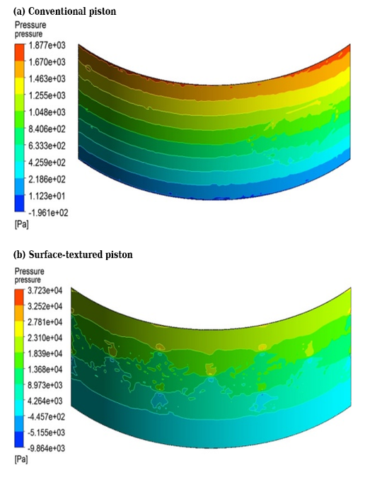
The lubricant-pressure distributions obtained from the CFX calculations are compared in Figure 3. As shown in Figure 3(a), the conventional piston exhibits a relatively smooth pressure variation over the investigated surface. In contrast, the surface-textured piston in Figure 3(b) shows a distinctly modified pressure field in the vicinity of the pits. Local pressure variations develop around the textured regions, indicating that the pits disturb the original lubricant flow and redistribute pressure along the piston–liner interface.
Figure 3. Lubricant-pressure distributions at the piston–liner interface: (a) conventional piston; (b) surface-textured piston
This pressure redistribution can be attributed to the disturbance of lubricant motion as the flow encounters the geometric discontinuity formed by the pit. The lubricant approaching the textured region is forced to adjust to the local change in surface geometry. The resulting variation in momentum produces a non-uniform pressure distribution around the cavity rather than the comparatively continuous distribution observed on the conventional surface. Similar geometry-dependent hydrodynamic responses have been reported for textured lubricated contacts, where the frictional response was found to depend strongly on texture geometry and operating conditions [17].
The most important implication is not simply the occurrence of a local pressure maximum. The textured surface changes the manner in which the lubricant carries load across the piston–liner interface. Regions of elevated pressure adjacent to the pits can contribute to local hydrodynamic support, while the cavity provides additional volume into which lubricant can enter. The combination of these effects modifies the local lubrication environment during reciprocating motion.
The numerical results therefore indicate that the pits act as active geometric features within the lubricant film rather than merely as empty surface defects. Their influence extends beyond the physical area occupied by each cavity because the pressure field immediately surrounding the pit is also modified. This provides a fluid-dynamic explanation for why a textured piston may exhibit improved durability even though its calculated maximum local friction stress is higher than that of a conventional piston.
Because the available simulations provide pressure-field distributions rather than complete spatially averaged pressure histories, the present comparison is intentionally limited to the observed pressure redistribution. No unsupported quantitative increase in mean film pressure or hydrodynamic load capacity is inferred from the numerical results.
4.3 Flow redistribution and recirculation induced by surface pits
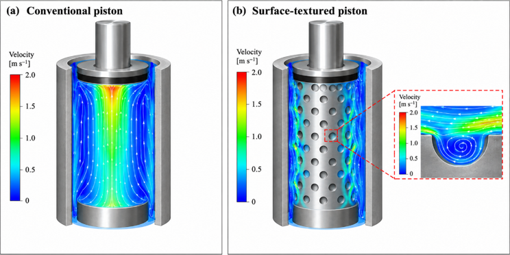
The lubricant-flow characteristics of the conventional and surface-textured pistons are compared in Figure 4. As shown in Figure 4(a), the lubricant over the conventional piston surface exhibits a comparatively continuous velocity distribution, without the localized flow disturbance associated with surface cavities. The flow remains broadly distributed along the piston surface under the imposed relative motion.
A distinctly different flow pattern is observed for the surface-textured piston in Figure 4(b). The pits interrupt the otherwise continuous lubricant flow and produce localized low-velocity regions around the textured areas. Part of the lubricant enters the cavities rather than continuing directly along the nominal piston surface. The enlarged local flow result in Figure 4(b) further shows recirculating motion within a pit, indicating that lubricant can remain temporarily trapped within the textured region before returning to the main flow.
This redistribution has two consequences. First, the pits increase the residence of lubricant within the immediate contact region. Lubricant entering a cavity is less readily swept away by the relative motion of the cylinder liner than lubricant located entirely on a smooth surface. Second, the local flow disturbance is consistent with the pressure redistribution observed in Figure 3. The pressure and streamline results therefore describe two aspects of the same hydrodynamic response: the surface geometry modifies the flow trajectory, and the associated momentum redistribution generates local pressure variations.
The observed recirculating behavior should not be interpreted as evidence that all pit geometries necessarily improve lubrication. A cavity that is excessively large or poorly configured may disturb the flow without providing a favorable balance between lubricant retention and mechanical integrity. The results of Section 4.1 support this interpretation because the mechanical response varies substantially among the nine textured configurations. Surface-texture design therefore requires simultaneous consideration of fluid-flow behavior and local mechanical loading.
Figure 4. Lubricant-flow characteristics at the piston–liner interface: (a) velocity distribution over the conventional piston surface; (b) velocity distribution over the surface-textured piston and local recirculating flow within a surface pit
4.4 Lubricant and wear-particle retention mechanism
In addition to modifying the pressure and flow fields, the surface pits provide local storage space at the piston–liner interface. This function becomes particularly important during prolonged reciprocating operation, when lubricant can be progressively displaced from the nominal contact region. As indicated by the flow characteristics discussed in Section 4.3, part of the lubricant entering a pit remains temporarily within the cavity rather than being transported immediately along the main flow path. The pits can therefore act as local lubricant reservoirs and increase lubricant residence within the textured regions.
A second function of the surface texture is associated with solid-particle accommodation. During mud-pump operation, mud particles and wear debris may enter the piston–liner interface. On an untextured surface, particles trapped between the two sliding surfaces can contribute to scratching, ploughing, and repeated abrasive interaction. Their presence can consequently aggravate local surface damage during continued reciprocating motion.
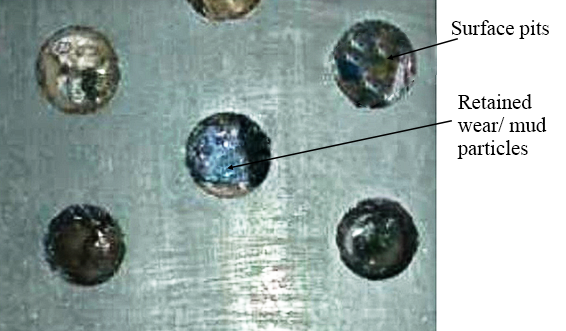
Figure 5. Wear and mud particles retained within the surface pits of the textured piston
Evidence of particle retention within the surface pits is shown in Figure 5. Wear debris and mud particles can accumulate within the cavities rather than remaining continuously within the principal sliding contact. The pits therefore provide additional accommodation space for entrained particles while simultaneously serving as local lubricant reservoirs. This combined retention function offers a plausible explanation for the reduced severity of surface damage observed on the better-performing textured piston.
The lubricant-retention and particle-accommodation mechanisms also help explain why the performance of the textured piston cannot be evaluated solely from the maximum friction stress. As demonstrated in Section 4.1, the introduction of pits increases the local maximum friction stress because of the mechanical discontinuity of the textured surface. At the same time, however, the cavities modify lubricant transport and provide storage space for both lubricant and solid particles. The overall tribological response therefore reflects the competition between the mechanical penalty introduced by the texture and the favorable changes in the local lubrication environment.
It should be noted that particle concentration, particle-size distribution, particle trajectories, and lubricant-retention volume were not quantitatively measured in the present study. The retention mechanism is therefore interpreted from the observed post-service condition of the pits together with the numerical lubricant-flow characteristics, rather than from a quantitative particle-capture efficiency. Further measurements would be required to determine the contribution of particle retention independently from the hydrodynamic lubrication effect.
4.5 Field validation of piston durability
Field tests were conducted to determine whether the numerical and mechanistic effects identified above translated into improved durability under actual mud-pump operating conditions. The conventional piston and two representative textured pistons were installed and operated under the same field conditions. A piston was considered to have reached the end of its service life when water absorption occurred in the mud pump, after which the piston was removed and its operating time was recorded.
The field results are summarized in Table 2.
The conventional piston operated for 271 h. Textured piston A reached 370 h, corresponding to a service-life increase of 36.53%, while textured piston B operated for 331 h, representing an increase of 22.14%. Both textured pistons therefore outperformed the conventional configuration despite exhibiting higher calculated maximum friction stresses.
Table 2. Field service life of the conventional and surface-textured pistons
|
Piston |
Corresponding Configuration |
D (mm) |
α (°) |
h (mm) |
Service Life (h) |
Improvement (%) |
|
Conventional piston |
Reference |
0 |
0 |
0 |
271 |
– |
|
Textured piston A |
Case 2 |
1.5 |
15 |
4 |
370 |
36.53 |
|
Textured piston B |
Case 8 |
4.5 |
15 |
2 |
331 |
22.14 |
The post-service wear morphologies provide further insight into this result. The conventional piston exhibited severe damage near the root region, including pronounced tearing at the rubber–nylon junction and substantial local material damage. In contrast, textured piston A mainly exhibited relatively shallow scratches extending from the root toward the lip, together with limited pits and gaps near the rubber–nylon junction. Severe surface damage was less evident than for the conventional piston.
Textured piston B showed a different failure pattern. Its relatively large pit diameter affected the integrity of the piston surface, and deformation near the root became more pronounced under operating pressure. This observation is consistent with the mechanical analysis: increasing the dimensions of the surface features can intensify the structural penalty even when hydrodynamic lubrication remains favorable.
The field results therefore provide an important validation of the overall design concept. Surface texturing did not improve durability by reducing the calculated maximum friction stress; instead, piston life increased despite the local stress increase. This behavior supports the interpretation that lubricant-flow redistribution, lubricant retention, and particle accommodation play substantial roles in the observed durability improvement.
4.6 Coupled mechanism of hydrodynamic lubrication and wear reduction
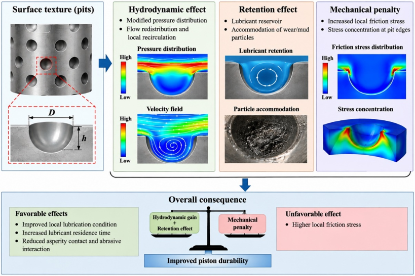
The numerical and field results indicate that the performance of the surface-textured piston arises from a coupled mechanical–hydrodynamic mechanism rather than from a single effect. The proposed mechanism, summarized in Figure 6, integrates the pressure redistribution and local flow modification observed in the CFD results with lubricant retention, particle accommodation, mechanical stress redistribution, and the field service-life response.
When lubricant encounters a surface pit during relative piston–liner motion, the local geometric discontinuity modifies the otherwise continuous flow path. Part of the lubricant enters the cavity, where local flow deceleration and recirculating motion can occur. At the same time, the change in lubricant motion is accompanied by a redistribution of pressure around the textured region. The pressure and flow results therefore represent two related aspects of the same hydrodynamic response: the pits disturb the lubricant trajectory and consequently modify the local pressure field.
The altered flow behavior also promotes lubricant retention within the textured regions. Lubricant entering a pit is less readily transported away with the main flow and can remain temporarily within the cavity. The pits consequently provide local lubricant-storage regions during reciprocating motion. This effect is particularly relevant to the mud-pump piston because repeated sliding can progressively displace lubricant from the nominal piston–liner contact region.
In addition to lubricant retention, the pits provide accommodation space for mud particles and wear debris. The post-service observations presented in Figure 5 show that solid particles can accumulate within the cavities. Their accommodation within the pits reduces the likelihood that all entrained particles remain continuously within the principal sliding contact, where repeated interaction with the opposing surfaces could contribute to scratching and abrasive damage. Lubricant retention and particle accommodation therefore represent two complementary functions of the surface texture.
These favorable effects are accompanied by a mechanical penalty. As demonstrated by the results in Table 1, all nine textured configurations produced higher maximum friction stresses than the conventional piston. The conventional piston exhibited a maximum friction stress of $\sigma_{\mathrm{f}, 0}=1.8785$ MPa, whereas the textured configurations ranged from 3.1180 MPa $\leq \sigma_{\mathrm{f}, \max} \leq 4.6384$ MPa. The introduction of surface cavities therefore changes the local mechanical response and can produce stress concentration. Increasing the dimensions of the surface features cannot consequently be regarded as an inherently favorable design strategy.
The overall mechanism illustrated in Figure 6 can therefore be understood as a competition between hydrodynamic and retention effects on one side and the mechanical penalty on the other. Pressure redistribution, local flow recirculation, lubricant retention, and particle accommodation can improve the local lubrication environment, whereas the geometric discontinuities introduced by the pits increase the maximum local friction stress. The final durability of the piston depends on the balance between these competing effects rather than on either mechanism considered independently.
The field results support this interpretation. Textured piston A (Case 2), with $D$ = 1.5 mm, $\alpha=15^{\circ}$ and $h$ = 4 mm, exhibited the smallest increase in maximum friction stress among the investigated textured configurations and achieved the longest measured service life of $T_{\mathrm{A}}=370$ h, representing an improvement of $\Delta T_{\mathrm{A}}$ = 36.53% over the conventional piston. Textured piston B (Case 8), with $D$ = 4.5 mm, $\alpha=15^{\circ}$, and $h$ = 2 mm, exhibited the highest maximum friction stress but still reached a service life of $T_{\mathrm{B}}$ = 331 h, corresponding to an improvement of $\Delta T_{\mathrm{B}}$ = 22.14%. These results indicate that the favorable lubrication and retention effects can outweigh the increase in local mechanical stress, although the magnitude of the durability improvement remains dependent on texture geometry.
The results also suggest that texture optimization should not pursue the largest possible pit dimensions or the strongest possible disturbance of the lubricant flow. A more appropriate design objective is to obtain sufficient hydrodynamic pressure redistribution, lubricant retention, and particle accommodation while limiting the associated increase in local mechanical stress. Within the range investigated in this study, Case 2 provided the most favorable balance among these effects and consequently produced the longest field service life.
Overall, the surface pits function as coupled mechanical and hydrodynamic elements at the piston–liner interface. This interpretation is consistent with the broader understanding of textured lubricated contacts, in which friction, wear, lubrication, and contact mechanics are governed by interacting rather than isolated mechanisms [18]. Their effectiveness is determined by the interaction among local stress redistribution, lubricant-pressure modification, flow recirculation, lubricant retention, and particle accommodation.
Figure 6. Proposed coupled mechanism of hydrodynamic lubrication, particle retention, and mechanical response in the surface-textured mud-pump piston
This study investigated the mechanical response, lubricant-flow behavior, wear characteristics, and field durability of a surface-textured piston for an F-1300 drilling mud pump. Numerical analysis and field tests were combined to clarify how regularly arranged surface pits affect the piston–liner interface. The main conclusions are as follows:
(1) Surface texturing substantially alters the local mechanical response of the piston. The conventional piston exhibited a maximum friction stress of $\sigma_{\mathrm{f}, 0}$ = 1.8785 MPa, while the maximum friction stresses of the nine textured configurations ranged from 3.1180 to 4.6384 MPa. Case 2 ($D$ = 1.5 mm, $\alpha=15^{\circ}$, $h$ = 4 mm) produced the lowest maximum friction stress among the textured configurations, $\sigma_{\mathrm{f}, 2}$ = 3.1180 MPa, corresponding to an increase of $\quad \Delta \sigma_{\mathrm{f}, 2}=\frac{\sigma_{\mathrm{f}, 2}-\sigma_{\mathrm{f}, \mathrm{o}}}{\sigma_{\mathrm{f}, 0}} \times 100 \%=\frac{3.1180-1.8785}{1.8785} \times$ 100% = 65.98%. In contrast, Case 8($D$ = 4.5 mm, $\alpha=15^{\circ}$, $h$ = 2 mm) produced the highest maximum friction stress, $\sigma_{\mathrm{f}, 8}$ = 4.6384 MPa, corresponding to an increase of $\Delta \sigma_{\mathrm{f}, 8}=\frac{\sigma_{\mathrm{f}, 8}-\sigma_{\mathrm{f}, \mathrm{o}}}{\sigma_{\mathrm{f}, \mathrm{o}}} \times 100 \%=\frac{4.6384-1.8785}{1.8785} \times 100 \%$ = 146.92%. The pits therefore introduce a mechanical penalty through local stress redistribution, and their geometry must be controlled to avoid excessive stress concentration.
(2) The CFX results show that the pits modify the hydrodynamic behavior of the lubricant film. Compared with the relatively continuous pressure distribution over the conventional piston, the textured surface produces localized pressure variations around the pits. Lubricant entering the cavities undergoes flow deceleration and local recirculation, resulting in a more complex flow structure and increased lubricant residence within the textured regions.
(3) The surface pits also provide local storage space for lubricant and entrained wear or mud particles. Lubricant retained within the cavities is less readily removed from the interface during reciprocating motion, while particles accommodated by the pits are less likely to remain continuously trapped between the principal sliding surfaces. These effects provide a physical explanation for the reduced severity of surface damage observed on the better-performing textured piston.
(4) Field tests confirmed that the hydrodynamic and retention effects can outweigh the increase in local mechanical stress. The conventional piston reached a service life of 271 h, whereas the service lives of the two representative textured pistons were 370 h and 331 h, corresponding to improvements of 36.53% and 22.14%, respectively. The configuration with the smaller increase in maximum friction stress achieved the longest field service life.
(5) The performance of the surface-textured piston is therefore governed by a balance between mechanical and hydrodynamic effects. Surface pits increase local stress but simultaneously redistribute lubricant pressure, modify the local flow field, retain lubricant, and accommodate solid particles. The results indicate that maximizing pit dimensions is not an appropriate design strategy. Instead, texture geometry should be selected to obtain sufficient lubricant-flow regulation while limiting the associated mechanical penalty.
Overall, the findings demonstrate that appropriately designed surface textures can improve the lubrication environment and extend the field durability of mud-pump pistons under severe reciprocating conditions. The combined numerical and field approach provides a practical basis for the hydrodynamic design of textured piston–liner interfaces. Further work should quantify the effects of operating pressure, reciprocating velocity, lubricant properties, and texture density and should incorporate detailed mesh-independence and experimental flow-field validation to establish more general design criteria for surface-textured mud-pump pistons.
This work was supported by the Doctoral Initiation Fund Project of Jilin Institute of Chemical Technology [Research on Wear Resistance of Bionic Pistons for Drilling Mud Pumps, grant number 2021030].
[1] Jiao, B.W., Liu, Y.Y., Li, T.Y., Lu, X.Q., Ma, X. (2022). Macro-texture in hydrodynamic lubrication: Effects of dimple parameter, density and distribution. Proceedings of the Institution of Mechanical Engineers, Part C: Journal of Mechanical Engineering Science, 236(15): 8703-8713. https://doi.org/10.1177/09544062221087552
[2] Xu, B., Yin, B.F., Jia, H.K., Hua, X.J., Wei, M.L. (2022). Effects of liner surface textures on the tribological performance of different production piston rings. Lubrication Science, 34(5): 356-368. https://doi.org/10.1002/ls.1594
[3] Ferreira, R., Carvalho, Ó., Sobral, L., Carvalho, S., Silva, F. (2023). Laser texturing of piston ring for tribological performance improvement. Friction, 11: 1895-1905. https://doi.org/10.1007/s40544-022-0723-5
[4] Cohen, I., Goltsberg, R. (2023). Partial surface texturing in hydrodynamic lubrication: A CFD-based investigation. Lubricants, 11(9): 395. https://doi.org/10.3390/lubricants11090395
[5] Wang, W., Zhao, W.H., Guo, P.Z., Liu, Q., Kouediatouka, A.N., Dong, G.N. (2023). A textured surface with oil inflow and outflow function designed for starved lubrication. Tribology International, 184: 108450. https://doi.org/10.1016/j.triboint.2023.108450
[6] Xie, Z.L., Li, J.X., Tian, Y.X., Du, P., Zhao, B., Xu, F.C. (2024). Theoretical and experimental study on influences of surface texture on lubrication performance of a novel bearing. Tribology International, 193: 109351. https://doi.org/10.1016/j.triboint.2024.109351
[7] Han, X.G., Chen, G.C., He, D., Shan, Y.C., Xu, J.J. (2022). Effect of laser surface texturing on the tribological properties and scuffing mechanism of CKS piston ring against cast iron cylinder liner under high intensifying. Tribology Transactions, 65(6): 1149-1159. https://doi.org/10.1080/10402004.2022.2134070
[8] Lü, Y.J., Kang, J.X., Zhao, X.W., et al. (2024). Effects of different surface textures on tribological performances of the cylinder liner-piston ring: An experimental study. International Journal of Engine Research, 25(3): 545-556. https://doi.org/10.1177/14680874231198357
[9] Luz, F.K.C., Profito, F.J., dos Santos, M.B., Silva, S.A.N., Costa, H.L. (2024). Deterministic simulation of surface textures for the piston ring/cylinder liner system in a free piston linear engine. Lubricants, 12(1): 12. https://doi.org/10.3390/lubricants12010012
[10] Huang, Q., Wu, C., Shi, X., et al. (2023). Tribological properties of AISI 4140 steel reinforced by bioinspired topological texture and multi-solid lubricants under starved lubrication. Tribology International, 187: 108692. https://doi.org/10.1016/j.triboint.2023.108692
[11] He, Y., Yang, J., Wang, H., Gu, Z., Fu, Y. (2022). Micro-dimple and micro-bulge textures: Influence of surface topography types on stick-slip behavior under starved lubrication. Applied Surface Science, 585: 152501. https://doi.org/10.1016/j.apsusc.2022.152501
[12] Zhang, C., Chen, J., Ji, B., Zhou, J., Zeng, L., Yang, Y. (2024). Effect of micro-dimple texture on the tribological performance of brass with titanium nitride (TiN) coating under oil-lubricated conditions. Coatings, 14(1): 119. https://doi.org/10.3390/coatings14010119
[13] Zhang, H., Gong, J., Liu, X., Sun, W., Sun, K., Bai, S. (2024). Influence of liner surface with parameterized pit texture on the friction characteristics of piston rings. Processes, 12(3): 572. https://doi.org/10.3390/pr12030572
[14] Amanov, A., Tsuboi, R., Oe, H., Sasaki, S. (2013). The influence of bulges produced by laser surface texturing on the sliding friction and wear behavior. Tribology International, 60: 216-223. https://doi.org/10.1016/j.triboint.2012.10.018
[15] Kovalchenko, A., Ajayi, O., Erdemir, A., Fenske, G. (2011). Friction and wear behavior of laser textured surface under lubricated initial point contact. Wear, 271(9-10): 1719-1725. https://doi.org/10.1016/j.wear.2010.12.049
[16] Borghi, A., Gualtieri, E., Marchetto, D., Moretti, L., Valeri, S. (2008). Tribological effects of surface texturing on nitriding steel for high-performance engine applications. Wear, 265(7-8): 1046-1051. https://doi.org/10.1016/j.wear.2008.02.011
[17] Rosenkranz, A., Costa, H.L., Profito, F., Gachot, C., Medina, S., Dini, D. (2019). Influence of surface texturing on hydrodynamic friction in plane converging bearings—An experimental and numerical approach. Tribology International, 134: 190-204. https://doi.org/10.1016/j.triboint.2019.01.042
[18] Sudeep, U., Tandon, N., Pandey, R.K. (2015). Performance of lubricated rolling/sliding concentrated contacts with surface textures: A review. Journal of Tribology, 137(3): 031501. https://doi.org/10.1115/1.4029770