Marwah Yousif Jalil* | Sarah H. Ali
© 2026 The authors. This article is published by IIETA and is licensed under the CC BY 4.0 license (http://creativecommons.org/licenses/by/4.0/).
OPEN ACCESS
Enhancing the thermal performance of heat exchangers is crucial for improving energy efficiency in diverse industrial applications, yet conventional baffle designs often face limitations such as high pressure drops and fouling. The thermo-hydraulic performance was examined by a series of three-dimensional computational fluid dynamics (CFD) simulations using ANSYS Fluent in a double-pipe counter-flow heat exchanger with two types of embedded semi-circular disc baffles (with and without grooves) in order to optimize the thermo-hydraulic performance. The baffles are arranged in two ways: one vertical and one at an angle of 30 degrees. The objective of this work is to investigate the coupled fluid-flow and heat-transfer characteristics between both circulating fluids, which are cold water as the main fluid with three cases of adding nanofluid particles of Ag, Al2O3, and TiO2 individually (with a volume fraction of 4%) and hot water used as a heating fluid. The two fluids enter the heat exchanger in opposite directions since it is configured to operate counter-currently. The investigations are completed within the turbulent flow range, and the Reynolds number (Re), which ranged from 4000 to 14000, was used as a standard for assessing the velocity. Regarding hot water, Re = 3000 was fixed. The outcomes report that the greatest overall performance gain was obtained from the nanofluid of Al2O3-H2O for the inclined grooved baffles case with a value of about 1.67, representing up to 65% enhancement in heat transfer compared to a smooth tube. The inclined configuration improved mixing and turbulence generation, whereas grooves further enhanced vortex formation and heat exchange uniformity. These findings demonstrate a novel approach that integrates optimized baffle geometry with high-performance nanofluids, surpassing previous efforts by simultaneously improving thermal efficiency and managing hydraulic penalties, offering a practical solution for next-generation heat exchanger designs.
heat transfer enhancement, nanofluids, heat exchangers, semi-circular baffles, turbulent flow
To reduce overheating, which could damage assemblies or other thermal system components, several heat transfer enhancement techniques are utilized in industrial applications. Thermal systems have a variety of applications [1]. The current trend is to use the heat transfer enhancement approach to increase the performance of thermal applications while saving energy and materials. It is possible to reduce the size and operational costs by implementing these approaches [2]. Numerous strategies are used in engineering and thermal processes to improve heat transfer. For example, twisted tapes and tubes have long been used to improve passive heat transmission in shell-and-tube heat exchangers, fluid transfer tubes, and heat exchangers [3]. Chemical processing facilities, solar heaters, power stations, and air conditioning units are just a few of the many thermal applications. Heat exchangers have become more important in the last few decades for a variety of applications, including offshore heat recovery, power production, and oil refining [4]. The baffle assembly is one of the most important parts of the heat exchanger because it directs the fluid flow from the shell side across the tube bundle in a way that maximizes heat transfer and keeps the exchanger's pressure drop within reason. Consider the most often used segmental baffles as an example [5]. By directing the outer side of the fluid to flow both uphill and downward between the tube bundle, the baffles improve local mixing and turbulence intensity, hence improving heat transfer [6]. However, due to structural limits, the segmental baffles contain certain intrinsic faults. (1) important bypass streams and leakage streams due to production tolerances; (2) large pressure drop resulting from baffles impeding fluid flow and flow separation near the baffle edge; (3) fouling established in the stagnation area close to the duct wall and the backside of the baffle plates; and (4) short operational lifetime due to flow-induced tube vibration [7, 8]. Owing to their improved thermophysical properties relative to conventional base fluids, nanofluids have demonstrated considerable potential for heat-transfer enhancement in thermal systems [9]. Numerous studies have been carried out to explore the advantages of employing nanofluid as a thermal fluid for the improvement of heat transmission in thermal systems since Choi’s [10] original study on the novel thermal fluid known as "nanofluid." They carefully considered variables such as the material, size, shape, concentration, and characteristics of the base fluid, as well as occasionally extra aspects, that affect its heat conductivity and viscosity [11]. According to recent studies, adding thermal radiation effects to systems based on nanofluids can improve heat transmission even more, particularly when temperature gradients are high. Examples include magnetohydrodynamic augmentation in heat sinks with cylindrical wings and spiral trapezoidal wings, as well as research on heat sinks featuring undulating fins and lateral ribs employing radiative nanofluids.
Researchers worked hard to test several geometric shapes with different distributions and introduce many details to reach the best heat transfer and performance of thermal systems. Among these studies are: He et al. [12] used a porous medium model in conjunction with a distributed resistance idea to perform a numerical analysis of three distinct heat exchanger designs. Three different types of shell-and-tube heat exchangers (finned tube banks, helical baffles, and vertical baffles) were simulated using the created codes and model. Numerical and experimental research was carried out by Lei et al. [13] on the hydrodynamics and heat transfer properties of a heat exchanger with baffles. Segmental, one-helical, and two-layer helical baffles were examined, and their respective performances were compared to achieve the best heat transfer. The outcomes reported that the heat exchanger with helical baffles provided greater thermal transfer coefficients at the same pressure drop than heat exchangers with segmental baffles, and that the two-layer helical baffle configuration offers better integrated performance than the one-helical baffle configuration. In an axially overlapping helical baffle heat exchanger, Bahiraei et al. [14] examined the convection heat transfer and pressure reduction properties of a water-Al2O3. According to their findings, as the concentration of nanoparticles grew, so did the features of convection heat transfer. Only when low-pressure-loss features were deemed more significant than heat transfer improvements were high nanofluid concentrations utilized.
Nashee and Mushatet [15] studied and contrasted the heat transfer behavior in a double-pipe concentric tube heat exchanger with and without triangle baffles. A series of experiments was conducted for this paper. In the current investigation, a triangle baffle with base measurements of 4.0 mm, height of 8.0 mm, and thickness of 1.5 mm is employed. Both cases have been used in the studies. It has been discovered that the presence of baffles increases the effectiveness of the cold fluid flow rate. The average effectiveness of the baffles also increases when their pitches are 50 mm and 100 mm, respectively, by 1.34 and 1.62 times in the smooth tube's counter-flow and 1.42 and 1.62 times in parallel flow. The effectiveness approach is employed to determine the total thermal performance.
Experimental research was done by Hussein and Hameed [16] on the water-air double pipe (HE). Semi-circular baffles with holes were added, with semi-circular fins on each baffle. Reynolds number (Re) was chosen to range from 2700 to 4000. It was found that the baffled pipe heat exchanger performed better thermally than the pipe without baffles. The outcomes of the heat transfer coefficient reported that there was an increase of 80.5%, 63%, and 29.5 more when perforated baffles with perforation widths of 20.0, 25.0, and 30 mm are used. Chen et al. [17], on the other hand, proposed a much simpler construction that they classified as a trisection helical baffle heat exchanger, with three sector-baffle plates. Compared to a traditional quarter helical baffle HE, the new shell-and-tube heat exchanger features fewer baffle components and a distinctive equilateral triangle tube layout.
Hussein [18] conducted a series of tests to study the behavior of turbulent flow in a double-pipe counter-water-flow heat exchanger with semi-circular disc baffles inserted at opposite lengths from the inner tube's outer surface. The pressure drops and heat transfer effects of turbulence were compared to smooth tube values. Every measurement was contrasted with the smooth tube's standard data. In the case when improving the heat transfer between the surfaces is the goal. Moreover, a numerical investigation was conducted by El Maakoul et al. [19] to test the thermo-hydraulic performance of a heat exchanger with two pipes, including helical baffles on the annulus side for various Re and baffle spacing (0.025–0.1 m). By comparing the numerical model with empirical correlations, the model was first validated for a basic two-pipe heat exchanger. The effects of helical baffles were then examined using the model. In comparison to the straightforward double-pipe exchangers, the outcomes achieved for a helically baffled annulus side showed increases in performance and pressure drop.
The impact of a circular, thin baffle on convection in an enclosure is investigated by Pushpa et al. [20]. The upper and bottom boundaries are maintained at adiabatic and impermeable conditions, while the inner and outer cylinder walls and the baffle are maintained at varying temperatures and concentrations. It has been noted that convective flow and the associated heat and mass transport properties are greatly influenced by the size and placement of the baffles.
Recently, Khanafer et al. [21] reported on natural convection to analyze the effect of a porous baffle fixed to the hot wall of an enclosure and reported that the presence of a porous fin alters the thermal transport, and the optimum fin location and angle are identified to obtain a higher heat transport rate. The current research deals with straight and inclined baffles, with and without grooves inside a double-tube heat exchanger. The study was carried out to test the thermal enhancement of these baffles by adding three types of nanofluids to the inner tube individually. The results showed that the case of inclined grooved baffles gives the best thermal enhancement. At the same time, the grooves help decrease the pressure drop through the tube. This represents the advantage of helping to decrease the drop in pressure in spite of the addition of the baffles that increase the turbulence of the flow, so we can get better heat transfer while trying to keep the pressure drop as low as possible.
By combining semi-circular baffles—both smooth and grooved, in straight and inclined orientations—with outstanding-performance nanofluids (AlO₃–H₂O, TiO₂–H₂O, and Ag–H₂O), the current work seeks to improve the performance of a heat exchanger with two tubes. The combined impact of optimal baffle configurations and various nanofluid compositions in turbulent flow has received little attention in earlier publications, which have mostly concentrated on traditional baffle configurations or single-type nanofluids. By empirically and numerically assessing the combined effects of baffle shape and nanofluid characteristics, our work fills this gap and seeks to improve heat transfer while minimizing pressure penalties in comparison to current designs.
2.1 Geometry description
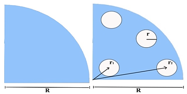
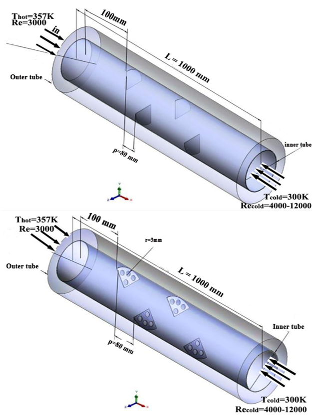
Utilizing a concentric tube heat exchanger and a comprehensive design of the thermo-hydrodynamic phenomena research (as in Figures 1 and 2) are provided, and Table 1 summarizes all examined configurations (nanofluids, baffle types, orientations). Understanding and characterizing the mass and heat transfer between the two circulating fluids—hot water utilized as a supplementary fluid and cold water as the primary fluid—is the goal of this work. Since the heat exchanger is set up in a counter-current manner, the two fluids enter through both ends of the exchanger and flow in opposing directions. In precise terms, hot water enters the system at a temperature of 357 K, whereas cold water enters at an initial temperature of 300 K. The outer tube measures 54 mm in diameter and 3 mm in thickness, while the inner tube measures 26 mm in diameter and 2 mm in thickness.
Figure 1. The semi-circular baffles with and without grooves
Figure 2. The schematic diagram of double tube heat exchanger
Table 1. The configurations (nanofluids, baffle types, orientations)
|
Nanofluid Type |
Baffle Type |
Orientation |
|
TiO₂–H₂O |
Semi-circular (Smooth & Grooved) |
Straight & Inclined |
|
Al₂O₃–H₂O |
Semi-circular (Smooth & Grooved) |
Straight & Inclined |
|
Ag–H₂O |
Semi-circular (Smooth & Grooved) |
Straight & Inclined |
Both tubes have a total length of 1000 mm, which guarantees a consistent flow pattern. Additionally, the external wall of the tube is made adiabatic, which ensures efficient thermal insulation and reduces energy losses from heat exchange with the outside environment. Semi-circular baffles are inserted into the partition wall of the inner tube. The first baffle is positioned L1 = 100 mm away from the tube entrance; this distance was carefully considered to prevent a depression from forming between the entering flow and the first obstacle that is met. Keeping a sufficient distance between baffles and the flow that enters reduces the likelihood of unwanted events like flow separation or elevated pressure losses, improves system performance, and lessens flow disruptions. The grooves have a radius of 3 mm with distances of r1 = 5 mm and r2 = 9 mm. Table 2 displays all the details of computational geometry.
Table 2. The computational model's geometrical requirements
|
Parameter |
Value |
|
Heat exchanger type |
Double-pipe counter-flow |
|
Total length |
1000 mm |
|
Inner tube inner diameter |
26 mm |
|
Inner tube thickness |
2 mm |
|
Inner tube outer diameter |
30 mm |
|
Outer tube inner diameter |
54 mm |
|
Outer tube thickness |
3 mm |
|
Outer tube outer diameter |
60 mm |
|
Tube material |
Copper |
|
Baffle material |
Copper |
|
Number of semi-circular baffles |
10 |
|
First baffle location |
100 mm |
|
Baffle radius (r) |
13 mm |
|
Baffle pitch (p) |
80 mm |
|
Baffle thickness |
3 mm |
|
Groove radius |
3 mm |
|
Groove spacing(r₁) |
5 mm |
|
Groove spacing (r₂) |
9 mm |
|
Baffle inclination angle (β) |
30° |
|
Hot fluid |
Water |
|
Cold fluid |
Nanofluid |
|
Flow arrangement |
Counter-flow |
Table 3 represents the thermophysical properties and provides references to the precise values we utilized in our tests. Understanding and characterizing the transfer of mass and heat between the two circulating fluids—hot water utilized as the secondary fluid and cold water as the primary fluid—the two fluids enter in opposing directions inside the tubes.
The following simple hypotheses were used in this investigation: (i) constant properties assessed at the inlet temperature; (ii) a single-phase nanofluid model with efficient thermo-physical properties, ignoring particle-base fluid slip; (iii) steady, incompressible turbulent flow; and (iv) no radiation or MHD effects, since the current work concentrates on baffle configuration and nanofluid kind, while such physics are recommended for future extensions; (v) Newtonian behavior without phase change; (vi) adiabatic exterior casing and no-slip at solid walls; and (vii) a suitable k–ε turbulence model for separated internal flows with improved wall treatment. Similar numerical heat transport studies frequently use these assumptions, and the conclusion acknowledges their limitations.
Table 3. Thermophysical properties of base fluid water (H2O) and solid nanoparticles [16]
|
Material |
$\boldsymbol{\rho}$ (kg/m3) |
Cp (J/kg K) |
K (W/m K) |
|
Al2O3 |
3950 |
531.8 |
76.5 |
|
Ag |
10.500 |
235 |
429 |
|
TiO₂ |
4050 |
683 |
1.134 |
|
Water |
997.1 |
4182 |
0.613 |
A pressure-based solver utilizing the SIMPLE method and second-order upwind discretization was employed to run the simulations in ANSYS Fluent. Convergence was reached when all residuals fell below 10⁻⁶, and the monitored Nusselt number (Nu) and pressure drop fluctuated by less than 0.1% using the realizable k–ε turbulence model with enhanced wall treatment.
Because of their exceptional chemical stability, low toxicity, cost-effectiveness, and relatively high thermal conductivity, oxide-based nanoparticles like AlO₃ and TiO₂ were selected for the current investigation. Furthermore, in water-based nanofluids, these nanoparticles show good dispersion stability, guaranteeing consistent and repeatable improvement of convective heat transfer in heat exchanger applications.
2.2 Boundary conditions
When this investigation was started, simplistic assumptions like turbulent and incompressible flow were used. At the inlet temperature, the fluid's physical characteristics remain unchanged by temperature. The pipe's outside wall is adiabatic, meaning that no heat is transferred across it. The outer wall of the heat exchanger was treated as adiabatic to prevent heat loss to the surroundings, while the interface between the inner and outer tubes allowed conjugate heat transfer between the hot and cold fluids. No constant wall temperature or heat flux condition was imposed, as heating was provided by the hot water stream in the annulus. At the outlet, a pressure outlet boundary condition with zero gauge pressure was applied, assuming fully developed flow; heat transport from radiation is disregarded. The inlet velocity profile shows a consistent flow distribution at the inlet. The conditions set at the boundary for the ongoing investigation are given in Table 4.
The following equations are used to calculate the values in Table 1 for each volume fraction that was investigated in this study. The same equation is observed in the study [10]. Density, viscosity, specific energy, and thermal conductivity are all represented by the corresponding equations. The section on nomenclature explains symbols and subscripts. For the fluid mixture's 300 K inlet temperature, fixed property values were chosen from tables. The thermo-physical characteristics of the base fluid and nanofluids were assessed at the inlet temperature and considered to be constant throughout this investigation. This assumption is supported by the heat exchanger's comparatively tiny temperature range (less than 50 K), which has been shown in prior research to have little effect on density, viscosity, and thermal conductivity [10, 11]. It is anticipated that temperature-dependent features will have little effect in the current arrangement, even if they can increase forecast accuracy in situations with greater temperature gradients. However, a sensitivity analysis or the implementation of temperature-dependent features is noted as a possible avenue for further research.
Table 4. The boundary conditions of the simulation
|
Boundary Ends |
Boundary Conditions |
|
Inlet |
Thot = 357 K, Tcold = 300 K, Recold = 4000-14000(2.24 × 10⁻⁴-7.87 × 10⁻⁴ m3/sec), Rehot = 3000 (5.47 × 10⁻⁵ m3/sec) |
|
Outlet |
(∂u/∂x = ∂v/∂y = ∂w/∂z = 0), zero gauge-pressure is specified at outlet domain |
|
Surfaces |
The velocity is taken to be zero (no slip), u = 0, v = 0, w = 0, ∂P/∂n = 0, where n is a normal unit vector |
As the temperature changes during heat transfer, the numbers computed in Table 1 stay the same. Since the temperature differential is no more than 50 K and variations in the values of properties that correspond to a temperature differential may be disregarded, this is not an issue and can be ignored.
$\rho_{n f}=(1-\varphi) \rho_{b f}+\varphi \rho_p$ (1)
$\left(\rho C_p\right)_{n f}=(1-\varphi)\left(\rho C_p\right)_{p f}+\varphi\left(\rho C_p\right)_p$ (2)
$\mu_{n f}=\mu_{p f}(1+2.5 \varphi)$ (3)
$k_{n p}=\frac{k_p+2 k_{b f}+2\left(k_p-2 k_{b f}\right) \varphi}{k_p+2 k_p-2\left(k_p-2 k_{b f}\right) \varphi} k_{b f}$ (4)
2.3 Mathematical modeling
The problem's mathematical formulation makes the assumption that the velocity of flow is constant with time, turbulent, and incompressible. The equations for continuity, momentum transfer, and energy flow in three dimensions (3D):
Equation of continuity [22]:
$\frac{\partial u}{\partial x}+\frac{\partial v}{\partial y}+\frac{\partial w}{\partial z}=0$ (5)
Momentum equations for x, y and z directions [22]:
$u \frac{\partial u}{\partial x}+v \frac{\partial u}{\partial y}+w \frac{\partial u}{\partial z}=-\frac{1}{\rho} \frac{\partial P}{\partial x}+\frac{\mu}{\rho}\left(\frac{\partial^2 u}{\partial x^2}+\frac{\partial^2 u}{\partial y^2}+\frac{\partial^2 u}{\partial z^2}\right)$ (6)
$u \frac{\partial v}{\partial x}+v \frac{\partial v}{\partial y}+w \frac{\partial v}{\partial z}=-\frac{1}{\rho} \frac{\partial P}{\partial y}+\frac{\mu}{\rho}\left(\frac{\partial^2 v}{\partial x^2}+\frac{\partial^2 v}{\partial y^2}+\frac{\partial^2 v}{\partial z^2}\right)$ (7)
$u \frac{\partial w}{\partial x}+v \frac{\partial w}{\partial y}+w \frac{\partial w}{\partial z}=-\frac{1}{\rho} \frac{\partial P}{\partial z}+\frac{\mu}{\rho}\left(\frac{\partial^2 w}{\partial x^2}+\frac{\partial^2 w}{\partial y^2}+\frac{\partial^2 w}{\partial z^2}\right)$ (8)
Energy equation [23]:
$u \frac{\partial T}{\partial x}+v \frac{\partial T}{\partial y}=\alpha\left(\frac{\partial^2 T}{\partial x^2}+\frac{\partial^2 T}{\partial y^2}\right)$ (9)
The single-phase effective- property formulation is used in this study to model nanofluids. The governing equations of Newtonian incompressible motion are maintained, and the impact of nanoparticles is included by altering the thermal and physical characteristics (ρ, μ, cp, k) in accordance with standard correlations. Particle–fluid slip mechanisms like Brownian motion and thermophoresis (as taken into account in the Buongiorno two-phase model) are not included, nor are any new transport equations for the particle phase solved. Numerical nanofluid studies with low particle densities and mild temperature gradients frequently employ this simplification. This approach's shortcomings are acknowledged, and future research is advised to compare it with two-phase models.
The mean heat transfer coefficient ($\underline{h}$) is calculated by the following expression [24]:
$\underline{h}=\frac{Q}{A_s\left(T_w-T_b\right)}$ (10)
where, the mean wall temperature is attained by [25]:
$T_w=\frac{1}{n} \sum T_{w n}$ (11)
The channel's bottom surface is Twn.
The following is the mean bulk temperature (Tb) [26]:
$T_b=\frac{\int_0^L \int_0^H \int_0^W \rho c_p u T d x d y d z}{\int_0^L \int_0^H \int_0^W \rho u d x d y d z}$ (12)
The mean Nu is estimated as follows [27]:
$N u=\frac{\underline{h} \cdot D_h}{k}$ (13)
where, $D_h$ is the hydraulic diameter of the tube.
The average friction factor (f) can be obtained by the following expression [28]:
$f=\frac{\Delta P}{\frac{1}{2} \rho u_{a v g .}^2} \cdot \frac{D_h}{L}$ (14)
Performance index [29] is computed for each example in order to compare the combined effects of increased pressure drop and improved heat transfer resulting from the introduction of a baffle at the same time.
$\eta=\frac{\left(N u_w / N u_o\right)}{\left(f_w / f_o\right)^{1 / 3}}$ (15)
Although Eqs. (6)-(9) are stated in a general conservation form, it should be emphasized that the nanofluid influences are integrated through their efficient thermophysical characteristics.
Eqs. (1)-(4) define them. These characteristics, which adhere to the common single-phase nanofluid model found in the study, take the place of the traditional fluid parameters in the governing equations.
The Realizable k–ε turbulent conditions model with improved wall treatment was utilized in every simulation. Because of its shown capacity to precisely forecast fully developed turbulent flows in interior channels, this model was selected. It is a good fit for the current setup because it has been thoroughly proven in the study for heat exchanger systems involving intricate flow separation and recirculating zones. It is a semi-empirical model with two equations: one for turbulent kinetic energy dissipation (ε) and another for turbulent kinetic energy transit (k).
For turbulent kinetic energy (k) [30]:
$\begin{gathered}\rho\left(\frac{\partial}{\partial x}(k u)+\frac{\partial}{\partial y}(k v)+\right. \\ \left.\frac{\partial}{\partial z}(k w)\right)=\frac{\partial}{\partial x}\left(\frac{\mu_t}{\sigma_k} \frac{\partial k}{\partial x}\right)+\frac{\partial}{\partial y}\left(\frac{\mu_t}{\sigma_k} \frac{\partial k}{\partial y}\right)+\frac{\partial}{\partial z}\left(\frac{\mu_t}{\sigma_k} \frac{\partial k}{\partial z}\right)+G-\rho \varepsilon\end{gathered}$ (16)
For energy dissipation rate (ε) [30]:
$\begin{gathered}\rho\left(\frac{\partial}{\partial x}(\varepsilon u)+\frac{\partial}{\partial y}(\varepsilon v)+\right. \left.\frac{\partial}{\partial z}(\varepsilon w)\right)\\=\frac{\partial}{\partial x}\left(\frac{\mu_t}{\sigma_{\varepsilon}} \frac{\partial \varepsilon}{\partial x}\right)+\frac{\partial}{\partial y}\left(\frac{\mu_t}{\sigma_{\varepsilon}} \frac{\partial \varepsilon}{\partial y}\right)+\frac{\partial}{\partial z}\left(\frac{\mu_t}{\sigma_{\varepsilon}} \frac{\partial \varepsilon}{\partial z}\right)+\rho \frac{\varepsilon}{k} G- C_{1 \varepsilon} \rho \frac{\varepsilon}{k}\end{gathered}$ (17)
where, G is referred to as the generation term and is given [30]:
$\begin{gathered}G=\mu_t\left[2\left(\frac{\partial u}{\partial x}\right)^2+2\left(\frac{\partial v}{\partial y}\right)^2+2\left(\frac{\partial w}{\partial z}\right)^2+\right. \\ \left.\left(\frac{\partial v}{\partial y} \frac{\partial u}{\partial x}\right)^2+\left(\frac{\partial v}{\partial z} \frac{\partial w}{\partial x}\right)^2+\left(\frac{\partial v}{\partial z} \frac{\partial w}{\partial y}\right)^2\right]\end{gathered}$ (18)
2.4 Mesh description
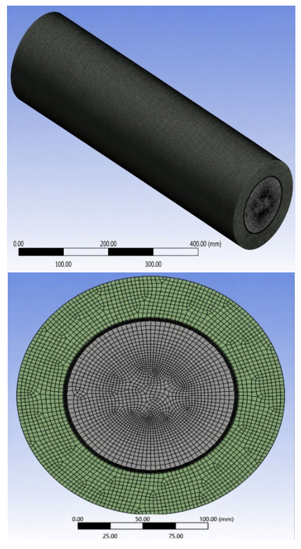
Governing equations stated in the previous section are solved by employing ANSYS FLUENT. The system of equations for the entire domain is solved iteratively employing the provided boundary. It is possible to create structured or unstructured grids and control volumes of various shapes, such as hexahedral and tetrahedral control volumes. Since the tetrahedral mesh is beneficial for the separation flow, it is used as illustrated in Figure 3. It is evident that the mesh is extremely tiny in order to capture the flow movements in the areas close to the surfaces and around the baffles.
Figure 3. The considered mesh generation of the tube and the cross-section
3.1 Grid independence study
To employ computational fluid dynamics (CFD) to model the flow of fluid problem, the geometry has to be split into cells which include a mesh. Selecting the right grid size is essential to obtaining accurate results. Testing of grid independence is carried out to establish the appropriate grid size for numerical simulations throughout a range of Re. The grid independence testing at Re = 4000 was used to determine Nu and friction factor (f). An overview of the outcomes is given in Table 5 along with the grid that is assigned to each form and configuration. Table 5 displays the grid independence of the outcomes.
Table 5. Different grids and their Nu and friction factor (f) for studied cases at Re = 4000 for Al2O3-H2O
|
Case |
No. of Grid Elements |
Nu |
Deviation between the Last Two Results |
f |
Deviation between the Last Two Results |
|
Smooth Tube |
631,180 |
34.744 |
|
0.0113 |
|
|
724,800 |
35.0212 |
|
0.0141 |
|
|
|
824,822 |
35.1043 |
0.0048 |
0.0146 |
0.68 |
|
|
843,564 |
35.106 |
0.0147 |
|||
|
Straight baffles |
3,211,634 |
55.365 |
|
0.0171 |
|
|
3,442,256 |
57.224 |
|
0.02 |
|
|
|
3,688,986 |
57.442 |
0.0039 |
0.0211 |
0.95 |
|
|
3,774,543 |
57.449 |
0.0213 |
|||
|
Straight grooved baffles |
3,496,376 |
59.667 |
|
0.0154 |
|
|
3,724,887 |
61.557 |
|
0.0185 |
|
|
|
3,879,015 |
61.762 |
0.0043 |
0.0193 |
0.52 |
|
|
3,978,543 |
61.769 |
0.0194 |
|||
|
Inclined baffles |
3,153,935 |
85.788 |
|
0.0241 |
|
|
3,217,632 |
87.449 |
|
0.0261 |
|
|
|
3,369,164 |
87.771 |
0.009 |
0.0266 |
0.37 |
|
|
3,534,522 |
87.779 |
0.0267 |
|||
|
Inclined grooved baffles |
3,076,744 |
94.204 |
|
0.0213 |
|
|
3,247,532 |
96.217 |
|
0.0247 |
|
|
|
3,389,561 |
96.322 |
0.0079 |
0.0252 |
0.79 |
|
|
3,432,455 |
96.343 |
0.0254 |
3.2 Benchmark comparison
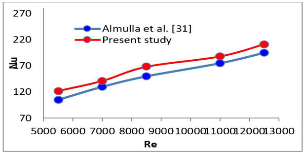
A benchmark comparison was carried out against the experimental data published by Almulla et al. [31] in order to evaluate the dependability of the current numerical model. It is important to note that the reference case was not replicated exactly. The current work takes into account 30° inclined semi-circular baffles with a 4% nanoparticle volume fraction, while the benchmark study used semi-circular baffles with a 90° orientation and an Al2O3–H2O nanofluid at a particle volume fraction of 1.5%.
Therefore, rather than offering a precise validation under comparable conditions, this comparison is meant to assess the numerical model's capacity to represent the proper thermo-hydraulic behavior.
Figure 4. The validation between the current simulation and Almulla et al. [31] work
Both investigations show the same physical pattern, which is a constant rise in the average Nu with rising Re, as seen in Figure 4. Given the significant variations in baffle orientation, nanoparticle concentration, and flow arrangement, the average discrepancy between the current numerical forecasts and the benchmark data is roughly 16%, which is deemed acceptable. While maintaining the same general thermal behavior, these geometric and operational alterations directly impact the turbulence intensity, secondary-flow generation, and the effective thermo-physical properties of the nanofluid, resulting in quantitative variances. As a result, the benchmark comparison validates that the current CFD model accurately replicates the governing physical trends documented in the study and consistently forecasts the thermo-hydraulic properties.
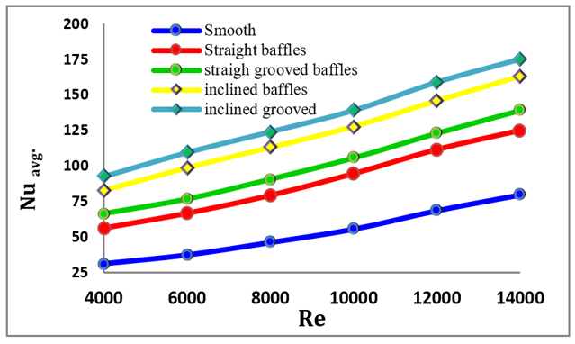
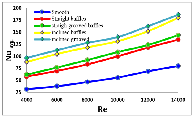
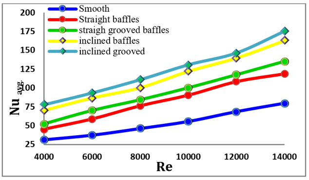
Figures 5–7 refer to the outcomes of the three simulated cases of nanofluids: (TiO2, Al2O3, and Ag) with H2O. Each figure explains a comparison of the results that gained from the presence of straight and inclined baffles, with and without grooves. The Nu was utilized to calculate the heat transfer rate for each heat exchanger in each of the evaluated cases. The relation between Nu and fluid flow velocity is depicted in the figures. In general, they exhibit a direct proportionality for each of the three nanofluid cases. The rise in Nu for the grooved baffles case was evident for all nanofluid cases. The presence of grooves clearly provided a benefit in terms of enhancing heat transfer. The explanation for this occurrence seems to be as follows: in a heat exchanger, impediments are encountered one after another by the flow pattern, and separation of streams at the edge of baffles results in a rapid shift in momentum and turbulent flow. At Re = 14000, the inclined semi-circular baffles increased the average Nu by approximately 31% compared with the straight tube for the Al₂O₃–H₂O nanofluid. Furthermore, compared with the smooth tube, the use of semi-circular inclined grooved baffles increased the average Nu by approximately 40–65%, depending on the Re (4000–14000), nanofluid type, and baffle configuration. The maximum enhancement was obtained for the inclined grooved baffles with Al₂O₃–H₂O at Re = 14000.
Figure 5. Nusselt number (Nu) results for TiO2-H2O
Figure 6. Nusselt number (Nu) results for Al2O3-H2O
Figure 7. Nusselt number (Nu) results for Ag-H2O
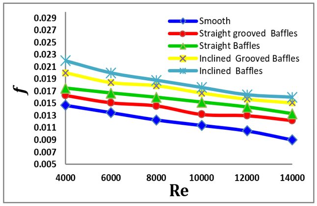
Greater turbulence and weakening of the thermal boundary layer cause Nu to rise with Re for all nanofluids; inclined-grooved baffles provide the strongest enhancement through enhanced secondary flows and vortex generation. Ag–H₂O's higher density and viscosity limit its relative benefits despite its intrinsic conductivity, whereas Al₂O₃–H₂O exhibits the best performance because of its highly efficient thermal conductivity and stability. Because of the additional form drag and cross-flow swirls caused by baffle insertion, the friction factor increases with baffle insertion but reduces with Re. The effects are especially noticeable in systems with inclined grooves.
Even though Ag nanoparticles have the highest intrinsic thermal conductivity, the proposed single-phase effective-property model predicts thermo-hydraulic performance based on the combined influence of all effective thermo-physical properties rather than just thermal conductivity. The flow field and convective heat-transfer coefficient (h) are altered by concurrent variations in effective viscosity, density, and specific heat. As a result, Al₂O₃–H₂O offers a better balance between flow characteristics and thermal enhancement, leading to a better overall (h).
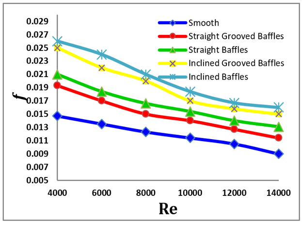
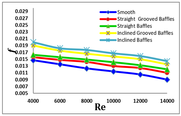
As regards the friction factor (f) outcomes, Figures 8–10 represent the comparison of the nanofluids (TiO2, Al2O3, and Ag) with H2O. The values of Al2O3-H2O give the greatest values of friction factor (f), followed by TiO2-H2O, then Ag-H2O. The outcomes report that a gradual decrease occurs for friction factor (f) as the Re rises. Also, there is a notable increase specially the grooved configuration, in the values of the friction factor (f) for inclined cases of baffles, especially the grooved, due to the inclination of baffles without grooves, causing the inserts' grooves to minimize pressure losses and air recirculation zones. This optimizes hydrodynamics. This interaction is responsible for higher pressure drop. The addition of grooves reduces the pressure-drop penalty in comparison to the corresponding ungrooved baffles, even though all baffled designs have greater friction factors (f) than the smooth tube because of the extra flow blockage. This phenomenon is explained by the creation of localized recirculation zones within the grooves, which partially minimize the wall-shear stress and create drag without sacrificing the improved fluid mixing, diminish the upstream stagnation region, and promote downstream flow reattachment.
Figure 8. Friction factor (f) results for TiO2-H2O
Figure 9. Friction factor (f) results for Al2O3-H2O
Figure 10. Friction factor (f) results for Ag-H2O
Thus, the friction factor (f) index becomes lower as Re increases up to Eq. (14). The improvement of the effective thermo-physical characteristics included in the single-phase model, specifically the enhanced effective thermal conductivity and the altered effective viscosity and density of the suspension, is the main cause of the rise in the Nu seen with nanofluids. Furthermore, the semi-circular baffles enhance fluid mixing and continually disturb the thermal boundary layer by encouraging flow separation, recirculation, and secondary vortex generation. Higher convective heat-transfer rates are produced by the inclined and grooved baffle arrangements, which also lessen the thickness of the thermal barrier layer and reinforce these secondary motions. Brownian motion and thermophoretic particle migration are not mentioned as direct mechanisms for the anticipated increase because the current work uses a single-phase effective-property formulation.
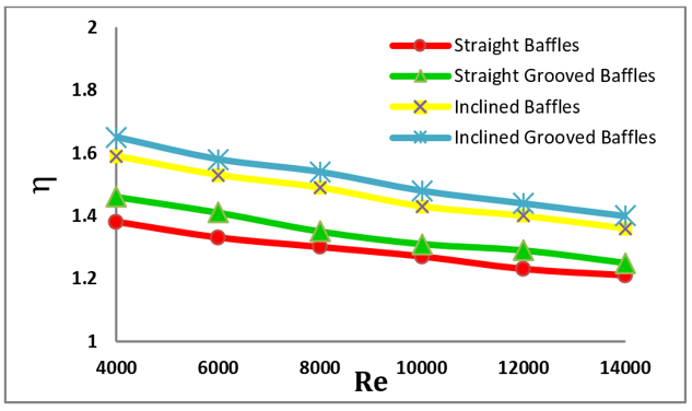
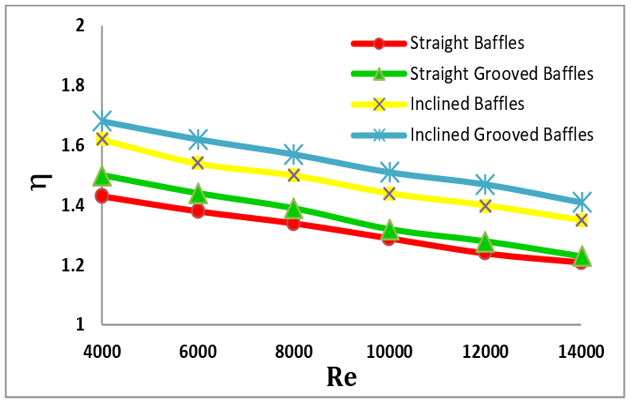
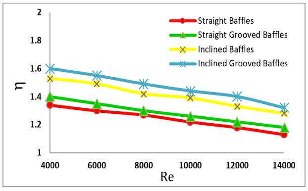
Figures 11–13 refer to the overall performance of the three simulated cases of nanofluids. According to the statistics, at Re = 4000, the thermo-hydraulic performance criterion (PEC) of Al₂O₃–H₂O was approximately 23% higher than that of TiO₂–H₂O and approximately 41% higher than that of Ag–H₂O for the inclined grooved baffle configuration. Furthermore, the findings demonstrated that by raising the turbulence of the fluid in motion and generating bigger recirculation zones, inclining the baffles improves the heat exchanger's overall performance. By inserting grooves into these baffles, this was enhanced and made more active since the grooves increased mixing, which in turn accelerated the rate of heat transfer. As a result, in the case of the inclined grooved baffles, the heat exchanger's total performance peaked. The highest overall performance rating was recorded for the case of inclined grooved baffles at Re = 4000. It amounted to 1.67 for Al2O3-H2O, 1.6 for TiO2-H2O and 1.51 for Ag-H2O. This interaction is responsible for a greater pressure drop friction factor (f) than the rise of heat transfer. Thus, the overall-performance index becomes lower at this configuration in comparison with the other cases. Because the improvements in nanofluid conductivity and baffle-induced turbulence balance the pressure penalty, PEC is highest at low Re. Because of its excellent conductivity and stability, Al2O₃–H₂O performs best in inclined-grooved baffles, which maximize PEC by producing vigorous secondary flows and minimizing stagnation. PEC decreases in all circumstances when Re rises because increasing pressure drop diminishes the relative benefit.
Table 6 summarizes the main percentage improvements covered in the preceding sections to increase the traceability of the quantitative results. The provided percentages can be clearly read and consistently compared thanks to this summary, which establishes a direct connection between the graphical results and the numerical discussion.
Figure 11. Overall performance results for TiO2-H2O
Figure 12. Overall performance results for Al2O3-H2O
Figure 13. Overall performance results for Ag-H2O
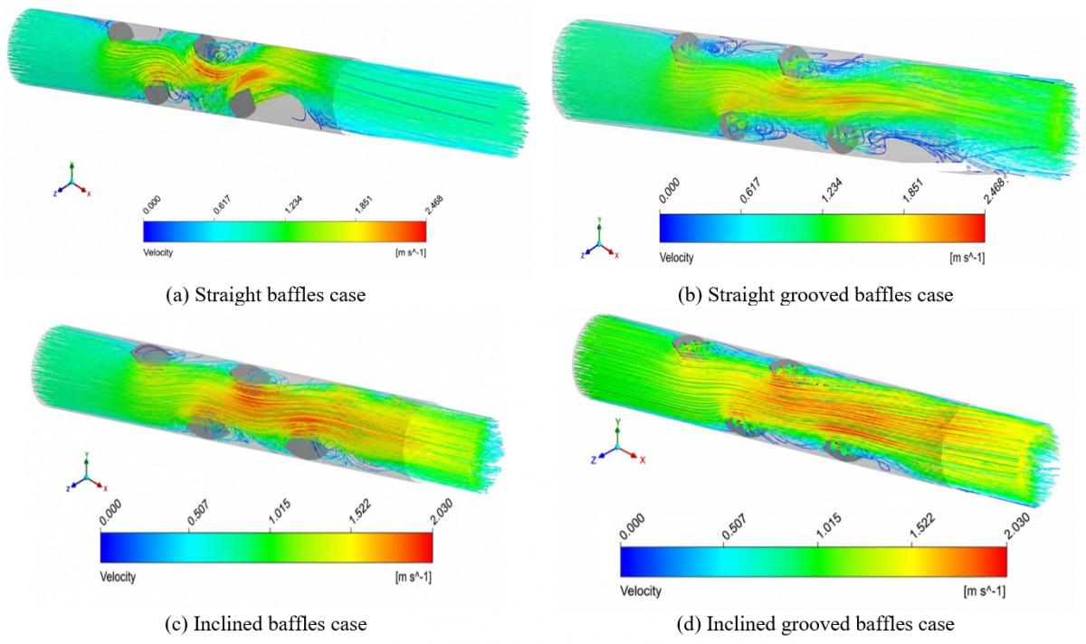
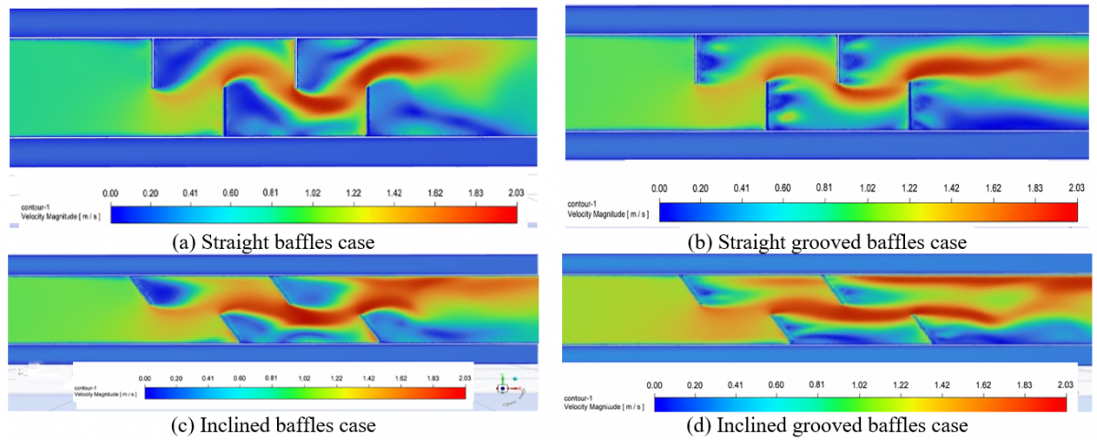
Figures 14 and 15 illustrate the contour and streamline plots of the anticipated velocity for the Al2O3-H2O working fluid in the straight baffles (with and without grooves) case and the inclined baffles (with and without grooves) case. The vortices are created close to the baffles in the core flow area, as seen in Figures 14 and 15. The disruption of the boundary layer and the uniformity of temperature in the center of the flow are largely due to longitudinal vortices.
The figures clearly show the variation that occurs in the form of flow between the four cases tested. The inclined baffle cases give more turbulence over a larger extent, a ripple shape, and a larger recirculation area than the straight cases. This indicates a positive effect of inclining the baffles on the mixing process and thus rising heat transfer. Not to mention the effect of the presence of grooves, which helped create greater turbulence and contributed to the improvement in vortex generation.
Table 6. A summary of the typical thermo-hydraulic performance
|
Statement in Discussion |
Variable |
Re |
Nanofluid |
Configuration |
Baseline |
Percentage Increase |
|
Inclined baffles Improve heat transfer |
Nu |
14000 |
Al₂O₃–H₂O |
Inclined Semi-circular Baffles |
Straight Semi-circular Baffles |
=31% |
|
Inclined groove baffles improve heat transfer |
Nu |
14000 |
Al₂O₃–H₂O |
Inclined Groove Semi-circular Baffles |
Inclined Semi-circular Baffles |
=28% |
|
Semi-circular baffles enhance heat transfer |
Nu |
4000–14000 |
All nanofluids |
All baffled configurations |
Smooth Tube |
=0–65% |
|
Best thermal enhancement |
Nu |
14000 |
Al₂O₃–H₂O |
Inclined Grooved Baffles |
Smooth Tube |
=65% |
|
Friction factor |
f |
14000 |
Al₂O₃–H₂O |
Inclined Semi-circular Baffles |
Straight Semi-circular Baffles |
=26% |
|
Friction factor |
f |
14000 |
Al₂O₃–H₂O |
Inclined Groove Semi-circular Baffles |
Inclined Semi-circular Baffles |
25% |
|
Superior thermo-hydraulic performance |
PEC |
4000 |
Al₂O₃–H₂O |
Inclined Grooved Baffles |
TiO₂–H₂O (same geometry) |
=23% |
|
Superior thermo-hydraulic performance |
PEC |
4000 |
Al₂O₃–H₂O |
Inclined Grooved Baffles |
Ag–H₂O (same geometry) |
=41% |
Figure 14. Streamline velocity of the four cases when Al2O3-H2O nanofluid as working fluid at Reynolds number (Re) = 4000
Figure 15. Velocity contour of the four cases when Al2O3-H2O nanofluid as working fluid at Reynolds number (Re) = 4000
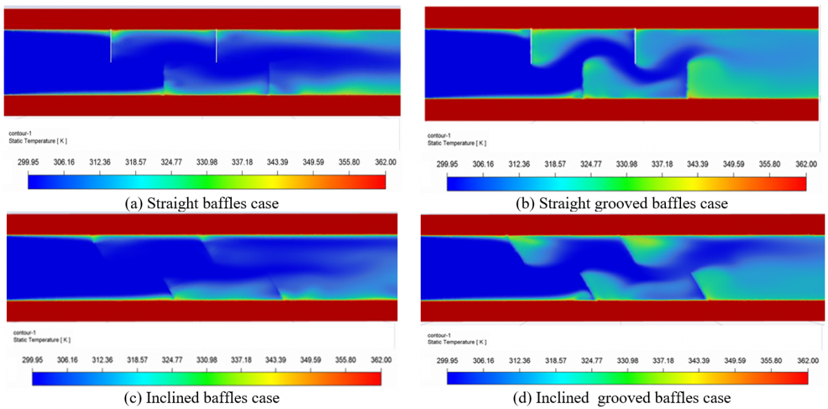
Figure 16. Temperature contour of the four cases when Al2O3-H2O nanofluid as working fluid at Reynolds number (Re) = 4000
Figure 16 illustrates how adding baffles impacts the temperature distribution in several cases. The presence of the baffles reorganizes the temperature distribution. The flow mixing has been raised results from turbulators with baffles inserted. The boundary layer of heat tends to be thicker in regions that are farther away from the ribs. The distribution of boundary layers (where the variety of temperature rises at(inclined grooved)) illustrates the effect of each instance. In general, employing baffles improves the temperature dispersion compared to the smooth tube.
Many important findings have been revealed by this study, which involved a thorough 3-dimensional evaluation of the effect of semi-circular baffle insertion on a heat exchanger's thermo-hydrodynamic behavior. A thorough examination of performance, the collected and examined data show considerable advancements in a number of important areas:
1. With a maximum Nu augmentation of about 31% over the corresponding ungrooved configuration and up to 65% over the smooth tube, the inclined grooved-baffle configuration utilizing Al2O3–H2O nanofluid produced the best thermo-hydraulic performance.
2. The heat-transfer improvement overcame the increased pressure-drop penalty, as evidenced by the maximum thermo-hydraulic performance index (PEC) of 1.67.
3. The addition of grooves decreased the pressure-drop penalty in comparison to the corresponding ungrooved baffles while preserving efficient flow mixing and heat-transfer enhancement, even though all baffled designs showed greater friction factors (f) than the smooth tube.
4. Under the examined conditions, the revealed performance trends offer helpful design direction for optimizing double-pipe heat exchangers using nanofluids and changed baffle configuration.
|
Dh |
Hydraulic diameter, m |
|
f |
friction factor |
|
h |
Convection heat transfer coefficient, W·m-2·K-1 |
|
K |
Turbulent kinetic energy, m2·s-2 |
|
L |
Length of Tube, m |
|
Nu |
Nusselt number |
|
P |
pressure, Pa |
|
r |
Radius of the grooves, m |
|
R |
Radius of baffles, m |
|
Re |
Reynolds number |
|
T |
Temperature, K |
|
Tw |
Wall temperature, K |
|
u |
Average velocity, m·s-1 |
|
U, V, W |
Velocity components, m·s-1 |
|
ΔP |
Pressure drop, Pa |
|
Greek symbols |
|
|
ρ |
water density, kg·m -3 |
|
η |
Thermo-hydraulic performance |
|
$\mu_t$ |
Turbulent viscosity, Pa·s |
|
Φ |
nanoparticle volume fraction, % |
|
Subscripts |
|
|
bf |
base fluid |
|
nf |
nanofluid |
|
in |
inlet |
|
p |
nanoparticle |
[1] Hu, Q.D. (2026). Application of heat pipe heat exchanger in flue gas waste heat recovery system. Journal of Physics: Conference Series, 3231(1): 012021. https://doi.org/10.1088/1742-6596/3231/1/012021
[2] Chokphoemphun, S., Phila, A., Promthaisong, P., et al. (2026). Heat transfer mechanism in turbulent channel flow with V-tapered-baffles: Effect of convergence and divergence direction V-baffles. Ain Shams Engineering Journal, 17(1): 103829. https://doi.org/10.1016/j.asej.2025.103829
[3] de Araujo Silva, R.A., da Costa, J.Â.P., Henríquez, J.R. (2026). Shell and tube heat exchanger with helical baffles and graphene nanofluids: A numerical thermal–hydraulic analysis. Chemical Engineering Science, 320: 122617. https://doi.org/10.1016/j.ces.2025.122617
[4] Rahman, M.A. (2025). Study the effect of axially perforated baffle plate with multiple opposite-oriented trapezoidal flow deflectors in an air–water tubular heat exchanger. World Journal of Engineering, 22(2): 322-333. https://doi.org/10.1108/WJE-10-2023-0425
[5] Faraj, R.Q., Al-Jassani, A.J.J., Al-Bugharbee, H.R. (2026). Numerical investigation on the performance of shell and tube heat exchanger with different porous baffles configurations. Heat Transfer. https://doi.org/10.1002/htj.70315
[6] Duraisamy, K., Narasimmalu, R. (2025). Optimizing heat exchanger performance and thermal efficiency using different fluid blends in power plants. Heat Transfer, 55(1): 168-182. https://doi.org/10.1002/htj.70067
[7] Nashee, S.R. (2024). Numerical simulation of heat transfer enhancement of a heat exchanger tube fitted with single and double-cut twisted tapes. International Journal of Heat and Technology, 42(3): 1003-1010. https://doi.org/10.18280/ijht.420327
[8] Bulduk-Sahin, K., Ozturk, M., Sahin, M., Erdogdu, F. (2025). Computational analysis of single-shell-pass shell-and-tube heat exchangers with novel curved baffles and various tube layouts. Innovative Food Science & Emerging Technologies, 106: 104243. https://doi.org/10.1016/j.ifset.2025.104243
[9] Batista, R.C., Rajendran, R.C. (2023). Computational analysis of thermal performance augmentation in helical coil heat exchangers via CuO/water nanofluid. Power Engineering and Engineering Thermophysics, 2(3): 139-149. https://doi.org/10.56578/peet020302
[10] Choi, S.U.S. (1995). Enhancing thermal conductivity of fluids with nanoparticles. In Proceedings of the ASME 1995 International Mechanical Engineering Congress and Exposition. Developments and Applications of Non-Newtonian Flows, San Francisco, California, USA, pp. 99-105. https://doi.org/10.1115/IMECE1995-0926
[11] Khaleduzzaman, S.S., Sohel, M.R., Saidur, R., Selvaraj, J. (2015). Stability of Al2O3-water nanofluid for electronics cooling system. Procedia Engineering, 105: 406-411. https://doi.org/10.1016/j.proeng.2015.05.026
[12] He, Y.L., Tao, W.Q., Deng, B., Li, X., Wu, Y. (2005). Numerical simulation and experimental study of flow and heat transfer characteristics of shell side fluid in shell-and-tube heat exchangers. In Proceedings of Fifth International Conference on Enhanced, Compact and Ultra-Compact Heat Exchangers: Science, Engineerin and Technology, Hoboken, NJ, USA, pp. 29-42. https://dc.engconfintl.org/cgi/viewcontent.cgi?article=1006&context=heatexchangerfall2005.
[13] Lei, Y.G., He, Y.L., Chu, P., Li, R. (2008). Design and optimization of heat exchangers with helical baffles. Chemical Engineering Science, 63(17): 4386-4395. https://doi.org/10.1016/j.ces.2008.05.044
[14] Bahiraei, M., Hangi, M., Saeedan, M. (2015). A novel application for energy efficiency improvement using nanofluid in shell and tube heat exchanger equipped with helical baffles. Energy, 93: 2229-2240. https://doi.org/10.1016/j.energy.2015.10.120
[15] Nashee, S., Mushatet, K.S. (2025). Performance study on turbulent heat transfer using rectangular air duct integrated with continuous and intermittent ribs turbulators. Thermal Science, 29(2): 955-967. https://doi.org/10.2298/TSCI240430214N
[16] Hussein, M.A., Hameed, V.M. (2022). Experimental investigation on the effect of semi-circular perforated baffles with semi-circular fins on air–water double pipe heat exchanger. Arabian Journal for Science and Engineering, 47: 6115-6124. https://doi.org/10.1007/s13369-021-05869-0
[17] Chen, Y.P., Sheng, Y.J., Dong, C., Wu, J.F. (2013). Numerical simulation on flow field in circumferential overlap trisection helical baffle heat exchanger. Applied Thermal Engineering, 50(1): 1035-1043. https://doi.org/10.1016/j.applthermaleng.2012.07.031
[18] Hussein, S.A.A. (2015). Experimental investigation of double pipe heat exchanger by using semi circular disc baffles. International Journal of Computer Applications, 115(4): 13-17. https://doi.org/10.5120/20138-2237
[19] El Maakoul, A., Laknizi, A., Saadeddine, S., Ben Abdellah, A., Meziane, M., El Metoui, M. (2017). Numerical design and investigation of heat transfer enhancement and performance for an annulus with continuous helical baffles in a double-pipe heat exchanger. Energy Conversion and Management, 133: 76-86. https://doi.org/10.1016/j.enconman.2016.12.002
[20] Pushpa, B.V., Prasanna, B.M.R., Do, Y., Sankar, M. (2017). Numerical study of doublediffusive convection in a vertical annular enclosure with a baffle. Journal of Physics: Conference Series, 908: 012081. https://doi.org/10.1088/1742-6596/908/1/012081
[21] Khanafer, K., AlAmiri, A., Bull, J. (2015). Laminar natural convection heat transfer in a differentially heated cavity with a thin porous fin attached to the hot wall. International Journal of Heat and Mass Transfer, 87: 59-70. https://doi.org/10.1016/j.ijheatmasstransfer.2015.03.077
[22] Mustafa, S.N., Abedalh, A.S., Hamode, F.Y. (2026). Assessment and enhancement of the performance of a shell and tube heat exchanger with metal foam baffles. International Communications in Heat and Mass Transfer, 178: 111862. https://doi.org/10.1016/j.icheatmasstransfer.2026.111862
[23] Lugo-Hinojosa, J.E., Martínez-Delgadillo, S.A., Yáñez-Varela, J.A., Garcia, A.A. (2025). Evaluation of flow patterns in a stirred tank equipped with tubular baffles using CFD numerical models and experimental PIV. Chemical Engineering and Processing - Process Intensification, 216: 110466. https://doi.org/10.1016/j.cep.2025.110466
[24] Shakir, R. (2021). Investigation of single-phase flow characteristics in an inline pin-fins complex geometry. Journal of Physics: Conference Series, 1879(3): 032118. https://doi.org/10.1088/1742-6596/1879/3/032118
[25] Alasiri, A., Fawaz, H.E. (2025). CFD investigation and ANN prediction of heat transfer coefficient for fully developed turbulent air flow around double V-baffle turbulators. Case Studies in Thermal Engineering, 71: 106096. https://doi.org/10.1016/j.csite.2025.106096
[26] Shakir, R. (2022). Study of pressure drop and heat transfer characteristics of mini-channel heat sinks. The Iraqi Journal for Mechanical and Materials Engineering, 22(2): 85-97. https://doi.org/10.32852/iqjfmme.v22i2.595
[27] Bouzennada, T., Fteiti, M., Alshammari, B.M., et al. (2024). Numerical study on nanofluid heat transfer and fluid flow within a micro-channel equipped with an elastic baffle. Case Studies in Thermal Engineering, 56: 104247. https://doi.org/10.1016/j.csite.2024.104247
[28] Mahdi, N.S., Eidan, A.A., Abada, H.H. (2026). Design and optimization of a compact u-shaped internal-condenser heat-pipe heat exchanger for high-ventilation heating, ventilation, and air conditioning in hot–dry climates. Heat Transfer, 55(4): 2328-2348. https://doi.org/10.1002/htj.70193
[29] Yılmaz, E.N.V.E.R., Sayani, J., Daneshfaraz, R., Süme, V.E.L.İ., Ebadzadeh, P., Marangoz, H.O. (2026). Experimental investigation of baffle configurations for enhancing hydraulic performance in fishways. Journal of Applied Fluid Mechanics, 19(5): 1037-1048. https://doi.org/10.47176/jafm.19.5.4000
[30] Moorthy, C.B., Vijayakumar, R., Madhu, P. (2025). Enhancing thermal performance of solar air heater using graphene nano coatings: A comparative study with and without baffles. Thermal Science and Engineering Progress, 60: 103498. https://doi.org/10.1016/j.tsep.2025.103498
[31] Almulla, N.M., Moawed, M.A., Abd Elrahaman, M.A., Salem, M.R. (2024). Study of the thermal performance characteristics of shell and semi-circular tube heat exchanger using both baffles and nanofluid. Engineering Research Journal (Shoubra), 53(2): 68-81. https://doi.org/10.21608/erjsh.2023.243774.1237