Thualfaqir J. Kadhim* | Abdalrazzaq K. Abbas | Hussein A. Mohammed
© 2026 The authors. This article is published by IIETA and is licensed under the CC BY 4.0 license (http://creativecommons.org/licenses/by/4.0/).
OPEN ACCESS
In this work, the impact of internal fin types on the hydrothermal performance inside a circular tube was numerically studied. The Reynolds number (Re) ranging from 8,000 to 24,000 was applied, and a heat flux load of 10 kW/m² was imposed. Using the finite volume method with the aid of ANSYS/Fluent 19 R3, the Navier–Stokes, continuity, and energy equations were solved. The improvement was studied with tubes of 10 mm inner diameter by using three fin types: pin, single longitudinal, and twin longitudinal fins for water as a working fluid to reach the optimal geometry. The numerical results showed that the performance of the finned tubes was significantly higher than that of the plain one, and the twin longitudinal fin has the highest convective heat transfer performance compared with the others. The influence of flow velocity on the friction factor is very weak, while it increases with fin technology compared to the smooth tube. Employing periodic extension between the tube inner area and the working fluid made the flow in the core along the tube more disturbed, causing a growth in the Nusselt number (Nu) up to 40%, and it is matched by an unwanted gain in pressure losses in the finned model, which were higher than those of the smooth model. In addition, with the same working conditions, the water temperature in the twin longitudinal finned tube was reduced by 1.5 K compared with the model that does not have fins on the inner surface.
turbulent forced convection, internal fins, Nusselt number, heat transfer augmentation
The expanding requirement for compact and efficient heat exchanger devices has been growing substantially in modern industrial applications, driven by the continuous increase in required heat transfer rates and the need for energy-efficient systems [1]. In such devices, enhancing the heat transfer from a working fluid to a solid surface, or vice versa, is a central challenge [2]. One of the most practical and widely adopted approaches for thermal augmentation is the use of fins, which act as extended surfaces to increase the effective heat transfer area and disturb the flow field [3]. The integration of fins disrupts the developing thermal boundary layer and generates localized secondary flows, which intensify convective heat transfer and consequently elevate the overall thermo-hydraulic performance of the channels. The effectiveness of fins, however, is strongly influenced by their geometry, arrangement, and orientation, as these factors directly affect both heat transfer and flow resistance. Consequently, designing innovative fin structures for internal tube surfaces has become an important area of research, aiming to achieve an optimal balance between augmented heat dissipation and the corresponding pumping power requirements [4, 5].
During the past few decades, numerous studies have shown that the act of measuring, positioning, and designing fins improves the heat transfer by forcing the fluid to flow turbulently, breaking up the boundary layer, and regenerating effectively in improving the thermal performance [6]. Zhu et al. [7] found that the overall coefficient of performance of the micro-channel with cavities as water droplets and elliptical rib columns was higher by 17.07% compared to channels that contain only cavities. Hussein et al. [8], through a numerical study, noticed that the thermal energy response was affected by the shape and configuration of the fins by an increase of up to 0.33% compared to the conventional case. Marzouk et al. [9] numerically studied the effect of several aspect ratios (Radius = 1, 2, 3, and 4) of pin-fins on thermal performance. Their results showed that using pin fins improves the rate of heat transfer by increasing the Nusselt number (Nu) value by 163%-242% at different aspect ratios and reducing the friction coefficient by 161%-290%. Zhang et al. [10] experimentally measured the 3D velocity components for a two-tube heat exchanger with spiral and pin fins. Their work pointed out that the presence of the fins resulted in turbulent flow and the appearance of vortices near the fins, which increased the turbulence intensity in the heat exchanger.
Liu et al. [11] offered a practical study of different pin-fin shapes (triangular, cylindrical, and cubic) using a micro-fin plate. The outcome established that the coefficient of heat and thermal resistance of the cubic pin-fins were significantly better. The cylindrical pin-fin exhibited less friction at a Reynolds number (Re) of 400. Cavazzuti et al. [12] numerically studied concentric finned tube heat exchangers. The results indicated that the achieved most favourable configurations enhanced the capacity of heat recovery exchange by 10.8% when operating at low thermal power (12.5 kW) and by 6.3% when operating at high thermal power. Yang et al. [13] established a numerical model to accurately predict the thermoelectric performance and thermo-mechanical behavior to achieve the best possible performance of circular finned thermoelectric generators. The results showed that fin height and diameter, as well as fin number, are important factors in thermal performance.
Hosseinpour et al. [14] investigated the effects of radius, length, and fin spacing on four types of microfins (pyramidal, conical, cubic, and cylindrical). The results exhibited that the fins of pyramidal shape ultimately achieved the best overall performance. Esmaeili et al. [15] numerically investigated the impact of turbulence on the thermal performance. The results indicate that incorporating a tapered pin-fin type of turbulence induces swirling flows, leading to a significant improvement in thermal performance. The increase in the Nu and pressure loss values was 87% and 73%, respectively. Ravanji et al. [16] studied the effect of oval pin fins from a concave surface on heat transfer experimentally and numerically. They found that this type of fin effectively improved the heat transfer and reduced the surface area required. Yeranee et al. [17] worked on increasing the thermal efficiency of the cooling channel by exploiting turbulent flow. The optimized model exhibits approximately 156.7% less pressure loss than the same solid-state model, at similar heat transfer. Rao et al. [18] studied the influence of different fin types, including pin fins, dimple fins, and hybrid fins, on the heat transfer performance of rectangular channels with average flow values ranging from 8200 to 54000 Re. The results showed that dimple fins contributed to reducing the pressure gradient and increasing the heat energy transfer. Wang et al. [19] studied ten models of pin-finned tubes to discuss the effect of various fin types on the thermal efficiency. They concluded that the heat transfer increased with increasing tube slope. Kotcioglu et al. [20] found that fin arrays improve thermal performance when arranged linearly, considering the differences between the types used in the study (square, cylindrical, and hexagonal). Mohsen et al. [21] discussed the influence of fin arrangement, spacing, and shape on the tube inside a two-tube heat exchanger. Their results showed that cylindrical pin fins outperformed conical fins, despite their equal total surface area. The Nu increased for conical fins by 20.22% and cylindrical fins by 13.95%, compared with the smooth tube. Mohammed et al. [22] discussed the influence of dimensions and roughness on thermal and flow performance by using circular tubes with transverse corrugations. They concluded in their results that the relationship between circular tubes' performance and Re is a direct and inverse relationship with surface roughness. Dhaidan et al. [23] numerically studied the hydrothermal behavior of a turbulent flow corrugated tube with forced convection inside. Three corrugated tube roughness patterns were studied: rectangular, semi-circular, and trapezoidal. The results pointed out that heat transfer was more efficient using both internal and external ribs compared to using only external ribs, but with additional pumping losses. At the greatest value of the Re of 60000, heat transfer was found to be 17.7% greater in the internal and external ribs of the tube. Ahmadian-Elmi et al. [24] presented numerical results for the coupled heat transfer in pin-fin radiators, and the influence of engineering parameters includes fin height, number of fins, tangent angle, and fin diameter. Their outcome indicated that changing the pin fin shape to a tapered one resulted in a worthy enhancement in thermal and hydraulic performance.
Although numerous studies have investigated heat transfer enhancement using various inserts, pin fins, and surface modifications, most approaches rely on adding external or internal fins or inserted elements, which can complicate manufacturing and increase flow resistance disproportionately. Far fewer works have examined the performance of fins integrated directly into the internal surface of tubes, particularly in the form of longitudinal configurations. This gap is significant because internal fins have the potential to enhance turbulence and disrupt the boundary layer more effectively while avoiding some of the drawbacks associated with inserts.
Moreover, comparative studies that systematically evaluate different internal fin geometries, such as single longitudinal, twin longitudinal, and pin fins, under identical conditions are still limited. The present study addresses this gap by numerically analyzing turbulent forced convection in tubes equipped with innovative internal fin designs. Using ANSYS Fluent, the hydrothermal performance of a smooth tube is compared with that of pin-fin, single longitudinal fin, and twin longitudinal fin configurations over a Re of 8,000-24,000. The focus is placed on quantifying improvements in Nu and wall temperature reduction while also assessing the associated pressure drop penalty. Internal fins represent a geometric trade-off between enhanced convective heat transfer and increased pumping power penalty. This study evaluates this thermal-hydraulic compromise across the investigated Re range and improved balance between different tubes designed through adopting a hydraulic diameter defined as the ratio of the total volume to the total inner surface area, rather than the conventional cross-sectional area divided by the wetted perimeter, which is highly accurate for various surface geometries, exhibiting variations in cross-sectional area along the tube inner surface.
2.1 Physical model
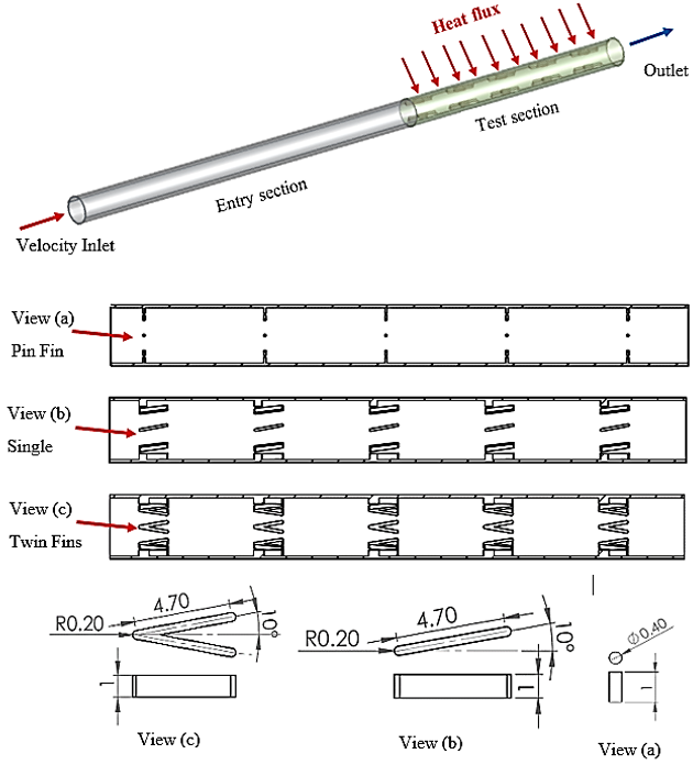
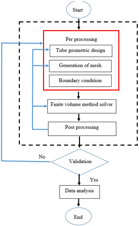
The 3D geometry shown in Figure 1 was designed and subsequently converted into a mathematical model using the design-modeler from Workbench and SolidWorks software. The geometric shape used in this study is a circular tube with 10 mm as inner diameter consisting of two sections. The first section represents the water entry with a length of 160 mm to ensure the flow is suitable (fully developed) in the test region, and the second section represents the test specimen with a length of 100 mm. Three models were constructed containing turbulence generators distributed into five groups in each test specimen, with 10 mm between each group and eight obstacles in each group, in addition to the smooth model that served as a reference. The test section is exposed to a heat flux of 10 kW/m2 on the outer face, and water flows through the finned tubes to minimize wall temperature. The four designs (smooth, pin, single longitudinal, and twin longitudinal fins) were adopted in this work to find out the impact of fin shape on the hydrothermal performance of the tubes. Previous studies indicate that the use of internal ribs in tubes or conduits contributes to improved thermal performance. Nevertheless, this improvement often leads to increased pressure loss. To obtain a better balance between improved heat transfer performance and reduced pressure loss, flow patterns that generate multiple longitudinal vortices have been proposed, which have the potential to increase the overall thermal efficiency of circular tubes. Based on these findings, this research presents an innovative finned tube with intermittently distributed on the inner wall only to improve thermal performance. Figure 2 shows the flow chart of the numerical simulation of the current work.
Figure 1. Finned models and dimensions
Figure 2. Flow chart of the numerical simulation
2.2 Materials and boundary conditions
The assumptions adopted in the numerical solution of this work are as follows [25]: Constant physical and thermal properties, incompressible flow and neglecting the effect of gravity. The boundary conditions adopted are introduced as follows [18]: The outer wall of the entrance section is set to be thermally insulated, the water inlet temperature is ($T_{\text {in}}$ = 300 K), and the gauge pressure at the model outlet is set to zero. The outer face of the test section is exposed to 10 kW/m2 as a heat flux. The physical and thermal properties of the copper tube and working fluid adopted are shown in Table 1 [26].
Table 1. Thermo-physical properties of copper and water
|
|
Viscosity (kg/m.s) |
Density (kg/m³) |
Heat Capacity (J/kg.K) |
Thermal-Conductivity (W/m.K) |
|
Water |
0.001003 |
998.2 |
4182 |
0.6 |
|
Copper |
------ |
8978 |
381 |
387.6 |
2.3 Governing equations
To complete the mathematical model and derive results for this system, the solver used was ANSYS Fluent to deal with the basic equations covering the flow and thermal fields. The continuity equation, the energy equation, and the momentum equations were solved based on the following assumptions:
The continuity Eq. (1) is:
$\frac{\partial u}{\partial x}+\frac{\partial v}{\partial y}+\frac{\partial \mathcal{W}}{\partial z}=0$ (1)
The momentum Eq. (2) is:
$\frac{\partial\left(v_i v_j\right)}{\partial x_j}=-\frac{\partial P}{\partial x i}+\frac{\partial}{\partial x j}\left(\frac{\partial v_i}{\partial v_j}-\rho \dot{v}_i \dot{v}_j\right)$ (2)
The energy Eq. (3) is:
$\frac{\partial}{\partial x_i}\left[v_i(\rho E+P)\right]=\frac{\partial}{\partial x_j}\left[\left(k+\frac{C_p \mu_t}{P r_t}\right) \frac{\partial T}{\partial x_j}+v_i\left(\tau_{i j}\right)_{e f f}\right]$ (3)
Due to the complexity of the geometric models and high Re in the present numerical study, the realizable k-ε is used as a model. The realizable turbulence model is believed to improve the predictability of complex turbulent flows with eddies and separations and may be superior to the standard k-ε model [20]. This turbulent model also includes two equations, the kinetic energy (k) and the dissipation rate (ε), as below:
$\frac{\partial}{\partial x_i}\left(\rho k v_i\right)=\frac{\partial}{\partial x_j}\left[\left(\mu+\frac{\mu_t}{\sigma_k}\right) \frac{\partial k}{\partial x_j}\right]+G_k-\rho \varepsilon$ (4)
$\frac{\partial}{\partial \mathrm{x}_{\mathrm{i}}}\left(\rho \varepsilon \mathrm{v}_{\mathrm{i}}\right)=\frac{\partial}{\partial \mathrm{x}_{\mathrm{j}}}\left[\left(\mu+\frac{\mu_{\mathrm{t}}}{\sigma_{\varepsilon}}\right) \frac{\partial \varepsilon}{\partial \mathrm{x}_{\mathrm{j}}}\right]+\left(\mathrm{C}_{1 \varepsilon}(\varepsilon / \mathrm{k}) \mathrm{G}_{\mathrm{k}}\right)-\left(\mathrm{C}_{2 \varepsilon} \rho \frac{\varepsilon^2}{\mathrm{k}}\right)$ (5)
where, $G_k$ is the kinetic energy of turbulent flow consequent to mean velocity gradients. The $\sigma_k$ is an effective Prandtl number and $\sigma_{\varepsilon}$ is the rate of dissipation of turbulent kinetic energy. The $\mu_t$ is eddy viscosity and $C_{1 \varepsilon}$ and $C_{2 \varepsilon}$ are constants.
2.4 Parameter description
The parameter descriptions in the present simulations were determined as follows [27, 29, 30]:
The Nu using the diameter of the test tube was calculated by:
$N u=h D_h / k$ (6)
$h(x)=q^{\prime \prime} / T_w(x)-T_b(x)$ (7)
The Re in the mentioned range for this turbulence problem at the tube entry are found as follows:
$R e=\frac{\rho v_{i n} D_h}{\mu}$ (8)
The hydraulic diameter $\left(D_h\right)$ is defined as:
$D_h=\frac{4 V_{\text {Fluid }}}{A_{\text {Wetted }}}$ (9)
The factor of friction with a constant fully developed flow regime is evaluated by:
$f=\frac{2 \Delta P D_h}{L \rho v_m^2}$ (10)
$\Delta P=P_{ {av,in }}-P_{ {av, out }}$ (11)
Established classical correlations were employed for computing and validating the Nu and f with their conditions, such as fully developed, turbulent flow, smooth surface, and circular section geometry, with Re in the values range of 3000 to ($5 \times 10^6$) [26].
The correlation of Gnielinski:
$N u=\frac{(2 f / 16)(\operatorname{Re}-1000) \operatorname{Pr}}{1.07+12.7(2 f / 16)^{1 / 2}\left(\operatorname{Pr}^{2 / 3}-1\right)}$ (12)
The correlation of Filonenko [27]:
$f=(1.82 \log R e-1.64)^{-2}$ (13)
It is valid for ($3000<\operatorname{Re}<5 \times 10^6$).
2.5 Computational domains and meshing
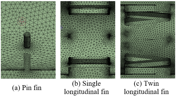
The computational mesh was generated using unstructured tetrahedral cells with inflation layers near the inner walls to improve mesh quality close to the wall regions. A second-order discretization scheme was used to partition the diffusion range and other variations, relying on the SIMPLE algorithm to relate pressure to velocity. Residuals were added well during iterations, and similarity criteria were adopted when the residuals were $10^{-6}$ for the continuity, velocity, and turbulence equations, and $10^{-11}$ for the energy. The turbulence model used was improved realizable k-ε [27]. The enhanced wall treatment was applied to the solid boundaries. To ensure the independence of solutions from the influence of the mesh, a series of simulations was conducted at Re of 12000, and several mesh densities were adopted. The number of elements ranged from 2 to 6 million elements, while the Nu values extracted at the wall for each mesh ranged from 129.05 to 124.71, respectively. It was found that the difference between the highest and lowest Nu values was approximately 3.36%, which is an acceptable value for numerical solutions. The mesh with (3403528) elements was selected as the optimal computational grid for all subsequent simulations. This choice provides an excellent compromise between numerical accuracy and computational economy; expanding the mesh density to a larger value results in minor and insignificant differences, a marginal variation in the Nu of only 2.1%. Figure 3 shows some parts of the mesh generated for the models that were adopted in the simulations.
Figure 3. Grids generated for the computation domains
A numerical study is conducted by simulating fluid flow and heat transfer in three tubes containing three different types of obstacles and one smooth tube for comparison, where water is adopted as a medium to transfer the heat from the tube wall. The hydraulic diameter serves as the basis for calculating the Nu, velocity, and coefficient of friction, while the inlet water temperature remained at 27 ℃. The entrance length i, >10 $D_h$ so the flow is fully developed at the test section [31, 32]. Then, it can be said that the flow is turbulent, and it has become fully developed in the centre of the tube. It is observed from the simulation results that the gain in heat exchange is accompanied by an increased pressure gradient due to the presence of fins on the internal face of the tube. Twin longitudinal fins are like a winglet, but they are integrated with all the wall’s connectors (multi-element), having a fixed shape to enhance local heat transfer with an increase in pressure penalty. This shape, with its tip, generates and redirects large-scale turbulent vortices to control span flow towards the tube core and inner wall, unlike an internal fin, with its limitation to break the boundary layer and create small turbulence to raise the transfer rate of heat over the inner surface area.
3.1 Validation of smooth tube
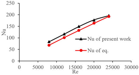
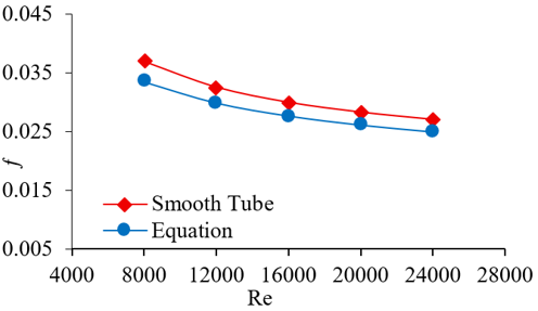
To establish confidence in the accuracy of the present numerical simulation, a thorough validation process was undertaken against well-established empirical correlations. Specifically, the Nu values obtained for the smooth tube configuration from the simulation were compared with those predicted by the renowned Gnielinski correlation. The results demonstrated a strong and favorable agreement, confirming the model's capability to accurately capture thermal phenomena. Similarly, the computational fluid dynamics model was further validated by analyzing the hydrodynamic behavior; the friction factor values for the smooth tube were rigorously compared against the established Filonenko correlation under identical flow conditions. This comparison also yielded highly acceptable results, falling within an expected margin of error. These critical validation exercises are graphically summarized in Figures 4 and 5, which collectively serve to confirm that the numerical predictions for both heat transfer and fluid flow are consistent with trusted theoretical benchmarks. Bolstered by this successful verification for the baseline case, the same rigorously tested numerical model and methodology were confidently applied to assess and compare the hydrothermal performance of the various innovative finned tube types. The Nu profile is provided in Figure 4 for various Re. It can be understood that the present results using $K-\varepsilon$ are in good agreement with Eq. (13) data from thermal viewpoints in comparison with the other models. Moreover, the highest deviation in the Nu profile, achieved by the CFD code for the tube, does not exceed 12%, indicating a quite agreement between numerical results and the empirical equation data.
Figure 4. Comparison of Nusselt number (Nu) for the present work and the Gnielinski equation in a smooth tube
Figure 5. Comparison of the friction factor (f) for the present work with Filonenko’s equation
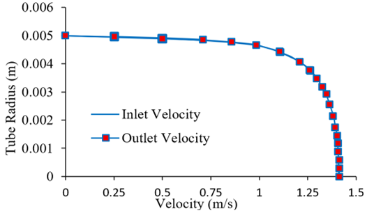
Figure 6. Comparison of the radial profile of axial velocity at the entrance and exit of the test section at Reynolds number (Re) = 12000
As reported previously, these correlations are valid for fully developed hydrodynamically and turbulent flow. The velocity profile overlay at the inlet (L = 160 mm) and outlet (L = 260 mm) of the test tube is quite good. Figure 6 shows that the velocity profiles change minimally across the selected section, indicating hydrodynamic stability. This observation is restricted to the velocity field, as the thermal boundary layer requires a separate development length under constant heat flux.
3.2 Convection performance of heat transfer
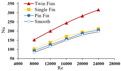
Figure 7 represents the relationship between the Re and the Nu, which represents the thermal behavior of smooth tube and finned tubes. It is evident from the graph that increasing the rate of flow leads to a gain in the Nu, especially in the case of the modified tube, where it is much higher than in the case of the smooth one. Increasing the flow velocity increases the amount of heat transfer rate due to mixing between the flow in the centre of the tube and the vortices generated by impingement on the fins. The highest Nu values were obtained in the twin longitudinal fin tube, followed by the single longitudinal fin and then the pin fin, while the lowest was the smooth one at the same Re values. Therefore, the use of different types of fins results in different thermal performance due to the generation of a specific flow motion in both the vertical and longitudinal directions. The outcome explains that the transfer of heat was increased by 40% in the case of the twin longitudinal fin compared to the tube without fins. The highest Nusselt number (Nu) of 316 is obtained for the twin longitudinal fin at Re = 24,000. Physically, the presence of obstacles in the way of the fluid flow leads to the disruption of the boundary layer near the hot wall of the tube, which causes an increase in the rate of heat transfer.
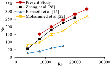
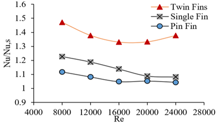
Figure 8 provides a qualitative overview comparing current Nu trajectories with previous thermal optimization concepts reported in the study [15, 22, 28]. Due to significant differences in reactor core configurations, flow measurements, and thermal boundary settings in these reference studies, a direct absolute comparison is not feasible. Instead, this qualitative comparison is used to verify that the enhancement in the Nu values in conjunction with the Re. Significant differences in the absolute curves are expected, as these differences vary according to the specialized engineering designs and thermal constraints of each independent study. Figure 9 describes the Nu ratio for finned and smooth tubes against Re, which provides a critical assessment of the relative thermal enhancement achieved by each fin geometry. The graph demonstrates that all finned configurations significantly improve heat transfer, with ratios consistently above unity, but reveals a clear performance hierarchy: twin longitudinal fin yields the highest enhancement, followed by single longitudinal fin, and then pin fin. This ranking is attributed to the twin fin's superior ability to disrupt the thermal boundary layer by creating the greatest flow obstruction and generating the most intense secondary flows and vortices, which forcibly mix the hot fluid near the wall with the cooler core fluid. Consequently, the figure quantitatively confirms that the twin longitudinal fin design is the most geometrically effective strategy for thermal augmentation, as its specific configuration maximizes turbulent mixing and heat transfer efficiency across the studied Re range.
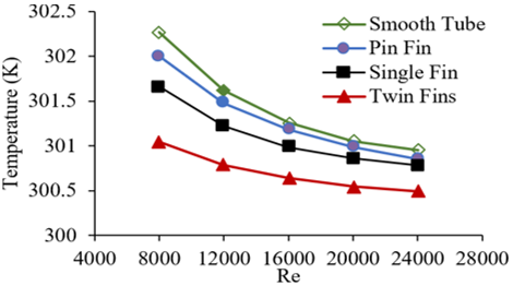
Figure 10 shows the average liquid temperature heating along the tube wall under different Re. The average wall temperature for all fin types reversely decreases with the Re. When the Re was 8000, the average values of temperatures of the liquid-heating with smooth, pin fin, single longitudinal fin, and twin longitudinal fin tubes walls were 302.3 K, 302 K, 301.6 K, and 301 K, respectively, which were lower than that value in the plain tube. This indicated that the structure of the twin longitudinal fin can effectively augment the heat transfer rate in the liquid-heating tube.
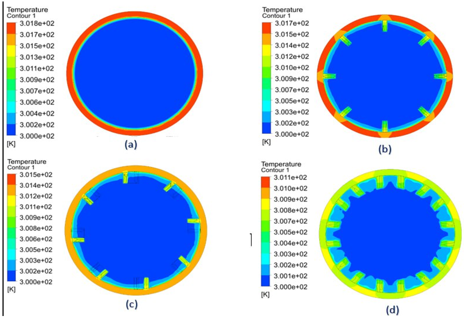
The spatial temperature contours across the plain and variously finned tubes at Re = 12000 are illustrated in Figure 11. The thermal profiles reveal a distinct non-uniformity. Notably, the regions surrounding the fins exhibit elevated temperatures compared to the intermediate tube walls. Among the studied geometries, the twin-fin configuration achieves the lowest average wall temperature, sequentially followed by the single-fin, pin-fin, and conventional smooth tube. This thermal behavior is primarily driven by enhanced vortex-induced fluid mixing inside the modified channels. The structural vortexes continuously draw cooler fluid from the central core toward the boundary walls while simultaneously projecting hot near-wall fluid back into the core stream. This intense core-to-wall exchange establishes steeper temperature gradients and suppresses the thermal boundary layer thickness, thereby dramatically augmenting the convective heat transfer performance.
Figure 7. Effect of fins inserted on Nusselt number (Nu)
Figure 8. Comparison of the present numerical Nusselt number (Nu) in the twin longitudinal fin tube with the previous studies [15, 22, 28]
Figure 9. Variation of Nusselt number (Nu) ratio with Re for different internal fin types
Figure 10. Average wall temperature along test section wall
Figure 11. Temperature distributions in transverse planes of the test section at Reynolds number (Re) = 12000: (a) smooth tube; (b) pin finned tube; (c) single longitudinal finned tube; (d) twin longitudinal finned tube
Figure 12. Pressure drop of smooth and finned tubes versus Reynolds number (Re)
Figure 13. Performance evaluation criteria (PEC) of finned tubes versus Reynolds number (Re)
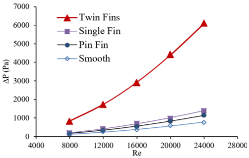
The influence of employing fins on pressure drop characteristics is described in Figure 12 to show the impact of the Re on the pressure gradient with different shapes of fins and plain walls. It was found that the pressure drop profiles were in a similar behaviour for all tubes, which is gradually increased with increasing Re. This might be described by the fact that at low values of the Re, corresponding to low flow rates, the working fluid could flow all over the fins' surface and produce a low pressure gradient due to the occurrence of minor vortices behind the fins. It was found that the test sections fitted with fins led to a higher-pressure drop than that of the tube without internal fins. The tube equipped with a twin longitudinal fin could produce the highest values of flow resistance compared to those found in the others, followed by the single longitudinal fin, and the pin fin.
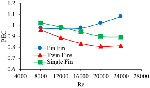
Figure 13 depicts the trend of the performance evaluation criteria (PEC), which is valued by using its equation and the Re. It can be understood from the figure that there is a regular augmentation for each fin type. The result exhibits that for both twin longitudinal and single longitudinal fins, the PEC have similar decreasing behavior, which is consistent with the results mentioned in the study [28]. Conversely, the pin-fin configuration shows an upward trend within the same (Re (span, driven by its reduced flow resistance. This divergence demonstrates that the PEC trend is heavily modified by pressure loss and does not identically match the Nu ratio shown in Figure 9. From what has been mentioned, it can be said that there is an optimum Re that maximizes PEC for each type of fins. The performance values of the fins vary from 0.8 to 1.07, while the highest PEC values for the other types are around 0.97 at a Re of 8000. In a space-limited application, the tube with the high heat transfer capability that also has a higher-pressure drop may be selected.
The PEC can be employed to estimate the effect of different internal fin types on the thermal behavior and fluid-dynamic efficiency of tubes and to appraise heat transfer augmentation. The PEC can be calculated using the predicted Nu and friction factors in the following order [27].
$P E C=\left(N u / N u_o\right) /\left(f / f_o\right)^{1 / 3}$ (14)
3.3 Characteristics of hydraulic performance
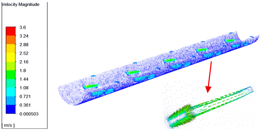
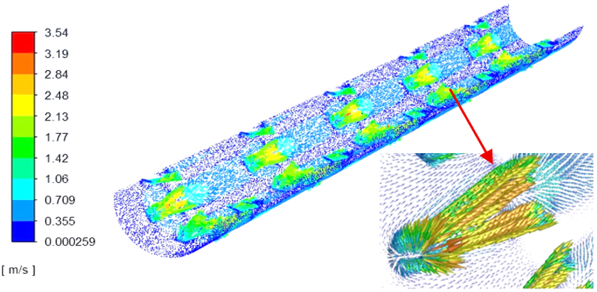
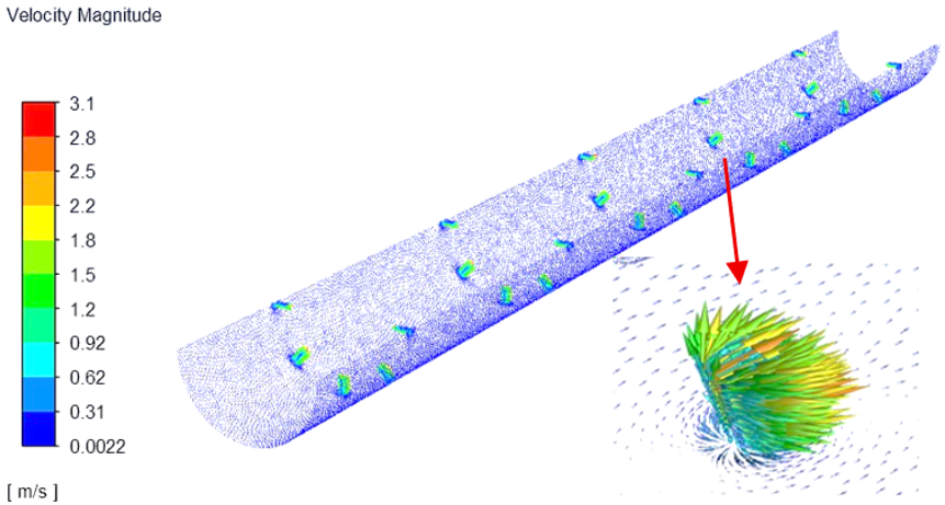
Figures 14-16 illustrate the velocity vector distributions for water flow within the single longitudinal, twin longitudinal, and pin-finned tubes at Re = 20,000. Across all geometries, the velocity fields exhibit axial symmetry. The integration of these fin structures induces localized recirculation zones that force the fluid within the near-wall boundary layer to mix continuously with the cooler core flow. This intense mixing disrupts and thins the thermal boundary layer compared to the smooth tube, establishing steeper temperature gradients near the heated walls. Consequently, the finned configurations yield significantly higher Nu, demonstrating a superior convective heat transfer performance over the plain tube.
In general, the presence of fins inside the tube obstructs the flow path and disrupts the stability of the thermal boundary layer near the wall, allowing it to be continuously regenerated and increasing the convective heat transfer, thereby increasing heat transfer efficiency and lowering surface temperatures. Conversely, these disturbances increase flow resistance and cause increased hydraulic loss, as pressure losses increase due to greater friction and shrinkage of the effective flow section. This improves thermal performance at the expense of increased flow resistance [28].
Figure 14. Velocity vector contour for water flow along the single longitudinal fin tube at Reynolds number (Re) = 20000
Figure 15. Velocity vector contour for water flow along the twin longitudinal fin at Reynolds number (Re) = 20000
Figure 16. Velocity vector contour for water flow along the pin fin at Reynolds number (Re) = 20000
The behaviour of the circular tube without and with fins was analysed numerically for a Re in the range of (8000-24000) using a designed CFD model. The geometry of the plain tube without fins was verified using the friction factor and Nu empirical correlations. For the geometry with fins, three different fin types were considered (pin, single longitudinal, and twin longitudinal fins). The models exhibited the following findings:
•The internal fins resulted in flow swirling and periodically mixing in the area near the tube and fins surfaces.
•The pressure losses throughout the tubes with fins were more than twice that of the tube without roughness.
•The velocity and temperature profiles were not uniform at the inner tube wall as compared to the finless tube, which leads to a growing process of cooling as the Re increases and increases the area covered by turbulence.
•About the pressure drop, the fins exhibited a significant influence on the profile of the total pressure, particularly close to the inner walls, and in the situation of the twin longitudinal fin, the effect was pronounced.
•The whole heat analysis exposed with the fins showed about (40%) heat transfer augmentation with twin longitudinal fin, and almost 8% and 4.5% enhancement with single longitudinal and pin fins, respectively.
In summary, the twin longitudinal fin configuration yields the peak Nu, making it highly favorable for applications where maximizing heat transfer intensity is the absolute priority. However, this configuration is constrained by a substantial pressure drop penalty and a PEC below unity. For optimal overall thermal-hydraulic trade-off at higher Re, the pin fin design emerges as the more efficient alternative due to reduced flow resistance.
|
$ C_p$ |
Heat capacity (kJ/kg. K) |
|
d |
Inside Diameter of Tube (m) |
|
$D_h$ |
Hydraulic Diameter (m) |
|
E |
Entire Energy (KJ) |
|
f |
Darcy Friction. |
|
h |
Coefficient of Heat Transfer (W/m2.K) |
|
K |
Kelvin |
|
k |
Fluctuating Kinetic Energy (J/kg) |
|
k |
Heat Conductivity (W/m. K). |
|
L |
Length of the Developed Section (m) |
|
Nu |
Nusselt Number |
|
Pr |
Prandtl number $ \left(\operatorname{Pr}=\mu . C_p / k\right)$ |
|
P |
Pressure of flow (N/m2). |
|
$ \Delta P$ |
Pressure Difference (Pa) |
|
$ q^{\prime \prime}$ |
Heat Flux $ \left(\mathrm{W} / \mathrm{m}^2\right)$ |
|
r |
Direction Along Radius |
|
$ V_{ {fluid }}$ |
Total volume of fluid |
|
$ A_{{wetted }}$ |
Wetted surface-area |
|
Re |
Reynolds Number |
|
T |
Temperature (Kelvin) |
|
v |
Velocity (m/s) |
|
$ \bar{v}$ |
Correction of Velocity (m/s) |
|
$ v^{\prime}$ |
Local Flow Velocity (m/s) |
|
$ u_t$ |
Kinematic eddy viscosity (m2/s) |
|
Greek Symbols |
|
|
μ |
Absolute Viscosity ($ \mathrm{N} . \mathrm{s} / \mathrm{m}^2$) |
|
ρ |
Density (kg/m3) |
|
τ |
Shear Stress $ \left(\mathrm{kg} / \mathrm{m}^2\right)$ |
|
ε |
Rate of Dissipation (m2/s3) |
|
Subscripts |
|
|
eff |
Effective |
|
in |
inlet |
|
w |
Wall |
|
b |
Bulk |
|
m |
Mean |
|
t |
Turbulent |
[1] Kadhim, S.A., Ashour, A.M., Sherza, J.S., et al. (2025). Review of insertion scenarios in enhancement performance of double-pipe heat exchanger: Case of cut twist tape. Chemical Engineering and Processing-Process Intensification, 213: 110308. https://doi.org/10.1016/j.cep.2025.110308
[2] Kadhim, S.A., Rasheed, R.H., Hammoodi, K.A., et al. (2025). Enhancing the thermal performance of double-pipe heat exchangers using wire coil inserts: A focused review. Scientific African, 29: e02896. https://doi.org/10.1016/j.sciaf.2025.e02896
[3] Maji, A., Choubey, G. (2020). Improvement of heat transfer through fins: A brief review of recent developments. Heat Transfer, 49(3): 1658-1685. https://doi.org/10.1002/htj.21684
[4] Zhu, X.L., Li, Y., Zhu, Q.Z. (2022). Heat transfer enhancement technology for fins in phase change energy storage. Journal of Energy Storage, 55: 105833. https://doi.org/10.1016/j.est.2022.105833
[5] Rashid, F.L., Alkhekany, Z.A.K., Kurji, H.J., et al. (2025). Enhancing the thermal performance of different types of heat exchangers with fins: A comprehensive review. International Communications in Heat and Mass Transfer, 166: 109177. https://doi.org/10.1016/j.icheatmasstransfer.2025.109177
[6] Li, L.J., Tang, Q.F., Chen, X.J., Weng, C. (2025). Polymer-based pin-fin microchannel heat exchangers: A comparative study of material and structural effects on performance. International Journal of Thermal Sciences, 209: 109546. https://doi.org/ 10.1016/j.ijthermalsci.2024.109546
[7] Zhu, Q.F., Su, R.R., Xia, H.X., Zeng, J.W., Chen, J.J. (2022). Numerical simulation study of thermal and hydraulic characteristics of laminar flow in microchannel heat sink with water droplet cavities and different rib columns. International Journal of Thermal Sciences, 172: 107319. https://doi.org/10.1016/j.ijthermalsci.2021.107319
[8] Hussein, H., Freegah, B., Saleh, Q. (2025). Investigation the influence of the number and configuration of fins on the hydrothermal behavior of a double-pipe heat exchanger. Journal of Engineering Research, 13(2): 1278-1293. https://doi.org/10.1016/j.jer.2023.11.006
[9] Marzouk, S.A., Almehmadi, F.A., Aljabr, A., Alam, T., Singh, T., Khargotra, R. (2024). Effects of extended pin fins on the hydrothermal performance of double pipe heat exchanger. Thermal Science and Engineering Progress, 55: 102915. https://doi.org/10.1016/j.tsep.2024.102915
[10] Zhang, L., Du, W.J., Wu, J.H., Li, Y.X., Xing, Y.W. (2012). Fluid flow characteristics for shell side of double-pipe heat exchanger with helical fins and pin fins. Experimental Thermal and Fluid Science, 36: 30-43. https://doi.org/10.1016/j.expthermflusci.2011.08.001
[11] Liu, C.Z., Zhao, P., Wang, S.W., Lyu, P., Liu, X.J., Rao, Z.H. (2025). Heat transfer enhancement of latent functional thermal fluid in microchannel with pin fins. International Journal of Heat and Mass Transfer, 244: 126921. https://doi.org/10.1016/j.ijheatmasstransfer.2025.126921
[12] Cavazzuti, M., Agnani, E., Corticelli, M.A. (2015). Optimization of a finned concentric pipes heat exchanger for industrial recuperative burners. Applied Thermal Engineering, 84: 110-117. https://doi.org/10.1016/j.applthermaleng.2015.03.027
[13] Yang, W.L., Jin, C.C., Zhu, W.C., et al. (2024). Taguchi optimization and thermoelectrical analysis of a pin fin annular thermoelectric generator for automotive waste heat recovery. Renewable Energy, 220: 119628. https://doi.org/10.1016/j.renene.2023.119628
[14] Hosseinpour, V., Kazemeini, M., Rashidi, A. (2020). Developing a metamodel based upon the DOE approach for investigating the overall performance of microchannel heat sinks utilizing a variety of internal fins. International Journal of Heat and Mass Transfer, 149: 119219. https://doi.org/10.1016/j.ijheatmasstransfer.2019.119219
[15] Esmaeili, Z., Vahidhosseini, S.M., Rashidi, S. (2024). A novel design of double pipe heat exchanger with innovative turbulator inside the shell-side space. International Communications in Heat and Mass Transfer, 155: 107523. https://doi.org/10.1016/j.icheatmasstransfer.2024.107523
[16] Ravanji, A., Zargarabadi, M.R. (2020). Effects of elliptical pin-fins on heat transfer characteristics of a single impinging jet on a concave surface. International Journal of Heat and Mass Transfer, 152: 119532. https://doi.org/10.1016/j.ijheatmasstransfer.2020.119532
[17] Yeranee, K., Rao, Y., Yang, L., Li, H. (2022). Enhanced thermal performance of a pin-fin cooling channel for gas turbine blade by density-based topology optimization. International Journal of Thermal Sciences, 181: 107783. https://doi.org/10.1016/j.ijthermalsci.2022.107783
[18] Rao, Y., Xu, Y.M., Wan, C.Y. (2012). An experimental and numerical study of flow and heat transfer in channels with pin fin-dimple and pin fin arrays. Experimental Thermal and Fluid Science, 38: 237-247. https://doi.org/10.1016/j.expthermflusci.2011.12.012
[19] Wang, Y.G., Liu, Y., Wang, X.Q., Zhao, Q.X., Ke, Z.W. (2021). Experimental study on the heat transfer and resistance characteristics of pin-fin tube. Thermal Science, 25(1A): 59-72. https://thermalscience.rs/pdfs/papers-2019/TSCI181216168W.pdf.
[20] Kotcioglu, I., Omeroglu, G., Caliskan, S. (2014). Thermal performance and pressure drop of different pin-fin geometries. Hittite Journal of Science and Engineering, 1(1): 13-20. https://doi.org/10.17350/HJSE19030000003
[21] Mohsen, A.M., Tukkee, A.M., Yao, T.A. (2024). A numerical analysis of cylindrical and conical pin fins configurations for enhancing heat exchanger performance. International Journal of Heat and Technology, 42: 1605-1612. https://doi.org/10.18280/ijht.420514
[22] Mohammed, H.A., Abbas, A.K., Sheriff, J.M. (2013). Influence of geometrical parameters and forced convective heat transfer in transversely corrugated circular tubes. International Communications in Heat and Mass Transfer, 44: 116-126. https://doi.org/ 10.1016/j.icheatmasstransfer.2013.02.005
[23] Dhaidan, N.S., Abbas, A.K. (2018). Turbulent forced convection flow inside inward-outward rib corrugated tubes with different rib-shapes. Heat Transfer-Asian Research, 47(8): 1048-1060. https://doi.org/10.1002/htj.21365
[24] Ahmadian-Elmi, M., Mashayekhi, A., Nourazar, S.S., Vafai, K. (2021). A comprehensive study on parametric optimization of the pin-fin heat sink to improve its thermal and hydraulic characteristics. International Journal of Heat and Mass Transfer, 180: 121797. https://doi.org/10.1016/j.ijheatmasstransfer.2021.121797
[25] Al-Obaidi, A.R., Chaer, I. (2021). Study of the flow characteristics, pressure drop and augmentation of heat performance in a horizontal pipe with and without twisted tape inserts. Case Studies in Thermal Engineering, 25: 100964. https://doi.org/10.1016/j.csite.2021.100964
[26] Incropera, F.P., De Witt, D.P. (2002). Fundamentals of Heat and Mass Transfer (Fifth edition). New York, John Wiley and Sons.
[27] Namburu, P.K., Das, D.K., Tanguturi, K.M., Vajjha, R.S. (2009). Numerical study of turbulent flow and heat transfer characteristics of nanofluids considering variable properties. International Journal of Thermal Sciences, 48: 290-302. https://doi.org/ 10.1016/j.ijthermalsci.2008.01.001
[28] Zheng, N.B., Liu, W., Liu, Z.C., Liu, P., Shan, F. (2015). A numerical study on heat transfer enhancement and the flow structure in a heat exchanger tube with discrete double inclined ribs. Applied Thermal Engineering, 90: 232-241. https://doi.org/ 10.1016/j.applthermaleng.2015.07.009
[29] Fluent Incorporated. (2001). Fluent 6 User's Guide.
[30] Ozceyhan, V., Gunes, S., Buyukalaca, O., Altuntop, N. (2008). Heat transfer enhancement in a tube using circular cross sectional rings separated from wall. Applied Energy, 85(10): 988-1001. https://doi.org/10.1016/j.apenergy.2008.02.007
[31] Wei, L.X., An, M.J., Xin, L.Z. (2011). Roughness enhanced mechanism for turbulent convective heat transfer. International Journal of Heat and Mass Transfer, 54: 1775-1781. https://doi.org/10.1016/j.ijheatmasstransfer.2010.12.039
[32] Gul, H., Evinb, D. (2007). Heat transfer enhancement in circular tubes using helical swirl generator insert at the entrance. International Journal of Thermal Sciences, 46: 1297-1303. https://doi.org/10.1016/j.ijthermalsci.2006.12.010