Yassine Taibi* | Benaoumeur Aour | Mekki Larabi | Kaddour Sadek | Abdellatif Oudrane
© 2026 The authors. This article is published by IIETA and is licensed under the CC BY 4.0 license (http://creativecommons.org/licenses/by/4.0/).
OPEN ACCESS
This study aims to analyze the long-term thermal behavior of a 3030 m deep borehole heat exchanger (DBHE) in Algeria and assess its suitability for geothermal energy extraction through a numerical model developed in ANSYS-CFX. The system is represented as a U-tube embedded in a stratified geological formation with distinct thermophysical properties, allowing simulation of transient fluid-soil heat transfer over extended operating periods. The model evaluates the effects of key variables, particularly inlet fluid temperature and flow velocity, which strongly influence heat extraction capacity and thermal stability. Results show a gradual decline in surrounding soil temperature during the initial years of operation, followed by quasi-steady-state conditions after approximately five years as thermal depletion rates diminish. Higher flow velocities enhance heat extraction, while lower inlet temperatures improve long-term outlet temperature stability. For a borehole depth of 3030 m, a 0.01 m pipe diameter, a 303.15 K inlet temperature, and a 0.5 m/s flow velocity, the predicted outlet temperature after five years is 366 K. Overall, the analysis demonstrates that deep abandoned oil wells in Algeria offer promising potential for repurposing as geothermal systems, contributing to the diversification and sustainability of the national energy mix.
geothermal energy, abandoned petroleum wells, finite volume, heat transfer, borehole heat exchanger
Geothermal energy is a key component of the global transition to sustainable energy systems, providing a renewable and reliable energy source that operates regardless of weather conditions. Unlike intermittent wind and solar power, which depend on natural variations, geothermal energy provides continuous baseload power to support grid stability and complement other renewable energy sources. Worldwide, geothermal power currently generates more than 94 TWh of electricity annually, or about 0.3% of the world's total electricity production [1]. Geothermal energy is recognized for its low carbon footprint, emitting approximately 99% less carbon dioxide than fossil fuel power plants of similar size, as reported by the Energy Information Administration [2]. Projections suggest that geothermal energy could meet up to 15% of global electricity demand by 2050, helping to reduce reliance on coal and gas significantly [3].
In the context of decarbonization and cost-effective energy solutions, the conversion of abandoned oil and gas wells for geothermal energy production holds great promise. Globally, there are millions of abandoned wells, with approximately 4 million located in the United States and Canada alone [4], representing a vast untapped infrastructure that could be used for geothermal energy production. Using these existing wells allows geothermal project developers to avoid the high costs associated with drilling new wells, which typically account for 40-60% of the total cost of geothermal projects [5]. In addition, the use of these wells can help mitigate environmental problems, as abandoned wells often leak methane, a potent greenhouse gas. Their conversion to geothermal wells addresses both energy and environmental challenges.
Research has shown that borehole heat exchangers (BHEs), including coaxial, U-tube, and twin-tube configurations, are particularly effective in extracting geothermal heat from these wells. These systems provide efficient heat transfer by circulating a working fluid through the well without the need for fluid extraction, thereby reducing the risk of corrosion and subsurface contamination [6]. As geothermal technology advances, the development of closed-loop systems using converted wells could significantly improve the economic feasibility and environmental sustainability of geothermal energy [7, 8].
Several studies have recently investigated the feasibility of extracting geothermal heat from abandoned oil wells. Gharibi et al. [9] found that U-tube systems maintain stable outlet temperatures over time. Hu et al. [10] demonstrated that deep-well doublet (deep borehole heat exchanger (DBHE)) systems outperform single-well DBHEs. Pokhrel et al. [11] carried out experimental and numerical analyses on a 500 m deep coaxial BHE system, reporting thermal power outputs between 172 and 262 kW. Chappidi et al. [12] showed that mono and hybrid nanofluids enhance geothermal energy extraction from abandoned wells. Cai et al. [13] showed that variable flow strategies improve thermal performance in double-well open-loop systems. Davoodi et al. [14] provide a broader synthesis of technical, economic, and environmental considerations for geothermal recovery from abandoned wells.
Recent studies have developed advanced numerical models to analyze heat transfer and fluid behavior in BHE systems installed in existing boreholes. These include simulations of thermal response [15, 16], comparisons between different configurations and working fluids [17-19], and evaluations of environmental and economic aspects [20].
Śliwa et al. [21] developed a detailed numerical simulation of a BHE using ANSYS CFX for an 180 m deep system, comparing numerical outputs with TRT measurements and showing accurate prediction of temperature evolution. Rees and He [22] proposed a 3D numerical model that resolves exchanger components and captures temperature variations over time scales ranging from seconds to decades. Their results show reliable long-term thermal behavior predictions.
Cheng et al. [23] modeled a 6000 m deep abandoned oil well using isobutane as the working fluid and identified an optimal inflow velocity that maximizes net electricity generation. Alimonti and Soldo [5] analyzed a deep well in the Villafortuna Trecate field (5800–6100 m), comparing water and diathermic oil; at a flow rate of 15 m³/h, water produced 1.5 MW of thermal power and 134 kW of net electricity.
Renaud et al. [1] modeled a deep BHE based on the IDDP-1 project in Iceland. Simulations performed over 30 years show a thermal peak of 1.2 MW after one year, with radial thermal disturbance expanding 10–40 m over the first decade.
Kharseh et al. [24] performed an optimization of operating parameters to maximize heat extraction from a geothermal well. They found an optimal flow rate between 3.7 and 4.4 kg/s, achieving 275 kW of heat extraction and stable generation of 11 kW of electricity over 25 years.
Recent research has increasingly focused on optimizing the performance of geothermal heat exchangers, whether U-tube, coaxial, or other closed-loop configurations, through numerical modeling, sensitivity analysis, and advanced optimization algorithms. Gao et al. [25] examined the heat-extraction performance of a 3,200-m-deep U-shaped geothermal well; they performed sensitivity analyses on injection flow rate, injection temperature, and subsurface thermal conductivities, ultimately identifying optimal operating conditions (~100 m³/h flow rate and ~10 ℃ injection temperature). These results underline the importance of parameter optimization for maximizing thermal efficiency in deep closed-loop systems.
Analytical approaches have also been proposed to simplify the assessment of coaxial DBHEs. For instance, Matyska et al. [26] developed a matrix-based analytical method to calculate heat extraction while accounting for variable geological conductivity and diffusivity; this provides a useful tool for evaluating the impact of operational parameters such as flow rate, geometry, and formation properties. Comparative studies such as Alimonti [27] between U-shaped and coaxial DBHE systems further highlight how geological conditions and application targets (heating vs. power generation) influence the optimal system configuration.
Other studies emphasize optimizing well geometry and operating conditions in repurposed abandoned wells. For example, Ma et al. [28] carried out parametric evaluations of U-shaped systems deployed in existing wellbores; their results demonstrate the importance of optimizing casing properties, cement characteristics, layout geometry, and thermal-hydraulic operation to maximize performance. Additionally, a comparative analysis of simulation tools for BHE optimization Heim et al. [29] showed that the choice of modeling approach (e.g., 3D computational fluid dynamics (CFD), g-functions, hybrid models) can substantially influence predicted outlet temperatures and thereby affect optimization outcomes.
Beyond single-well optimization, recent work has extended parameter optimization to field-scale problems. In the study of Szklarz et al. [30], a stochastic optimization framework that integrates geological uncertainty and geomechanical constraints was applied to determine optimal well locations, well types, and production/injection rates in a stratified reservoir. Their findings highlight the need to account for subsurface mechanics and uncertainty when designing and operating geothermal systems at the field scale. Similarly, Zeng et al. [31] simulated multi-field coupling thermal, hydraulic, and fluid flow processes, showing how injection pressure, fracture density, and fracture aperture influence heat extraction. This guides the selection of optimal injection strategies and production planning.
Recent advances in optimization algorithms and artificial intelligence provide new perspectives for geothermal system design. For example, Chong et al. [32] proposed a surrogate-assisted evolutionary algorithm to optimize heat extraction in enhanced geothermal systems (EGS), exploring a wide design space while reducing computational cost; their framework adjusts well-control conditions to maximize thermal efficiency. This type of approach is particularly promising for designing optimized geothermal systems in complex contexts including repurposed deep abandoned wells where multiple conflicting objectives must be balanced.
Although many studies have explored the geothermal potential of abandoned oil and gas wells, a persistent gap remains regarding the long-term thermal behavior of very deep closed-loop systems operating in hot, stratified geological formations such as those found in southern Algeria. Most recent works focus on shallow to medium-depth exchangers, double-well configurations, or general techno-economic assessments, while very few transient 3D models calibrated with real North African data exist, which limits the reliability of local predictions and the optimization of operating strategies for this region. For example, a recent study on a geothermal site in northeastern Algeria showed that the identified hydrothermal resources could enable electricity production through an indirect Organic Rankine Cycle (ORC) system, confirming the technical feasibility of this approach while revealing constraints related to fluid temperature and site configuration [33]. Similarly, research on thermal waters and aquifers (Albian reservoirs, thermal springs) in southern and northwestern Algeria confirms the existing geothermal potential but does not address the dynamic long-term behavior of deep borehole heat exchangers [34]. To address this gap, the present study develops a detailed 3D numerical model of a U-tube heat exchanger in ANSYS CFX, based on real data from a 3030 m abandoned well in Algeria, and systematically analyzes the combined influence of mass flow rate, inlet temperature, insulation length, and pipe diameter. This contribution provides new insights for optimizing heat recovery from deep converted wells and supports the development of geothermal energy in North Africa.
This paper aims to propose solutions to maximize heat recovery from abandoned oil wells and thereby contribute to better exploitation of geothermal resources. To this end, a 3D numerical model of a U-tube heat exchanger has been developed and simulated using ANSYS CFX software. The model is based on real data from an abandoned well in southern Algeria. The influence of four key parameters on the performance of the geothermal heat exchanger, namely mass flow rate, fluid inlet temperature, insulation length, and pipe diameter, has also been highlighted.
2.1 Physical model (borehole heat exchanger geometry)
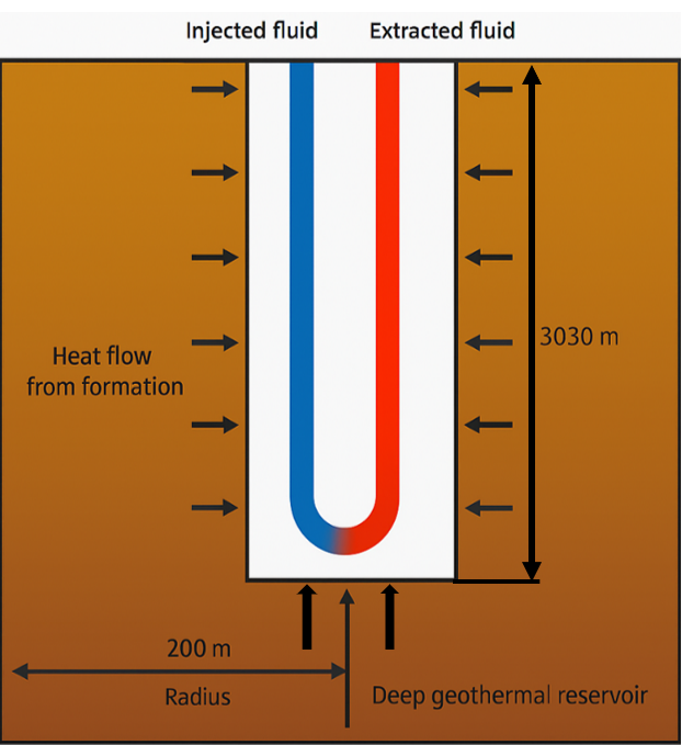
The geometry studied in this paper consists of a U-tube heat exchanger. It is based on an abandoned oil well in southeastern Algeria. In this region, gas wells are usually drilled at depths ranging from 2800 to 4200 m. In this study, a depth of 3030 m has been selected. The borehole is filled with a suitable material called grout. Water, used as the working fluid, is injected into the well through the inlet tube and absorbs the geothermal heat as it circulates through the stainless-steel tube, as shown in Figure 1. The optimum insulation length is determined based on its effect on the performance of the geothermal heat exchanger. The temperature of the solid domain is defined as a function of the geothermal gradient in the ground, which is assumed to be linear, increasing from 298 K at the surface to 400 K at the well bottom. The outer radius of the domain has a zero-heat flux condition, representing the far field where the ground is unaffected by heat transfer in the vicinity of the well. To ensure the validity of this condition, it was verified that there was no change in temperature at or near the boundary after each simulation. The radius of this boundary was set to 200 m for all simulations. The borehole geometry, the different soil layers and their thermophysical properties are presented in Tables 1 and 2.
Figure 1. Schematic diagram and boundary conditions of the U-tube DBHE for geothermal production from abandoned oil wells
Table 1. The depths and thicknesses of different ground layers
|
Layer Index |
Type of the Layer |
Depth (m) |
Thickness (m) |
|
|
From |
To |
|||
|
1 |
Limestone |
0 |
164 |
164 |
|
2 |
Clay |
164 |
954 |
790 |
|
3 |
Anhydrite |
954 |
1850 |
896 |
|
4 |
Salt |
1850 |
2776 |
926 |
|
5 |
Clay |
2776 |
2921 |
145 |
|
6 |
Sandstone |
2921 |
3260 |
339 |
Table 2. Thermo-physical properties of the geological layers
|
Material Properties |
Density [kg/m3] |
Thermal Conductivity [W/m‧K] |
Specific Heat Capacity [J/kg‧K] |
|
Limestone |
2410 |
2.58 |
932 |
|
Clay |
1880 |
1.63 |
1286 |
|
Anhydrite |
2964 |
0.51 |
858 |
|
Salt |
1156 |
4.77 |
886 |
|
Sandstone |
2308 |
2.65 |
873.68 |
|
Stainless Steel |
8032 |
16.31 |
503 |
|
Water |
998 |
0.61 |
4182 |
|
Insullation |
3000 |
0.027 |
2545 |
2.2 Numerical model
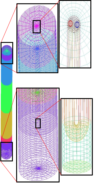
Based on the proposed well configuration shown in Figure 1, a three-dimensional numerical model is developed in a Cartesian coordinate system. To model the geometry, we first create the U-tube (consisting of an elbow and two pipes), then define the grout volume surrounding the U-tube, and finally model the soil surrounding the entire computational domain. The generated volumes were meshed using Gambit with a hybrid mesh consisting of tetrahedra, hexahedra, prisms, and wedges. An expanding mesh was chosen in the radial direction to minimize the total number of cells. This results in a refined mesh near the wall, where the largest gradients occur, and a coarser mesh further out, with an expansion factor of 1.2 (see Figure 2). However, several tests were performed to ensure that the simulation solutions were independent of the mesh size in the vertical direction (z) and the time step ∆t. To this end, each parameter was progressively increased to optimize the number of elements while reducing memory usage and computation time.
Figure 2. Finite volume meshing of the U-tube borehole heat exchanger (BHE)
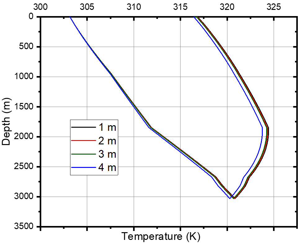
A separate independence study was performed for each parameter: ∆z and ∆t. Grid and time step independence was determined using a case with an inlet temperature of 303.15 K and an inlet velocity of 0.5 m/s, with the same temperature gradient and surface temperature as before, over five years of operation. Simulation results for all three models show that increasing the step size ∆z (1 m, 2 m, 3 m) does not significantly affect the results obtained (see Figure 3). Therefore, a grid size of 3 m along the z-axis is used for the following calculations of this work. The time step was set to 3600 s. The system outlet temperature did not vary by more than 0.50% between successive decreases in parameter size.
Figure 3. Evolution of fluid temperature after 5 years of operation, grid sensitivity testing in z-direction
It is worth noting that the model was simulated in transient mode. According to the sensitivity study, the optimum value of the soil radius is 200 m (Figure 4), and its depth is considered to be 200 m above the well depth. The entire numerical model, including the U-tube heat exchanger, working fluid, grout, and surrounding soil, consists of 661536 cells.
Figure 4. Outlet fluid temperature after 5 years of operation, grid sensitivity test in the x-direction at W = 0.5 m/s and T = 303.15 K
2.3 Governing equations
The method used in this study is based on numerical modeling using ANSYS CFX software. The CFD solver is based on the finite volume method. The most widely used k-epsilon (k-ε) turbulence model is employed for numerical simulations. An incompressible, transient flow is assumed, taking into account the gravitational force and the effects of turbulence. Due to the considerable length of the domain, most of the heat transfer occurs underground, making surface effects negligible. The heat transport around a geothermal heat exchanger in a borehole is described as a function of the Cartesian coordinate system and time. This phenomenon is also related to fluid flow, involving convective heat transfer from the fluid to the U-tube, followed by conduction through the grout and surrounding rock. Note that convective heat transfer in the rock can be neglected due to the absence of an aquifer layer with water filtration. In this case, the heat transfer in the rock is modeled by the transient heat conduction equation known as the Fourier-Kirchhoff equation, which is given as follows:
$\rho c_p \frac{\partial T}{\partial t}=\nabla \cdot(k \nabla T)$ (1)
where, ρ is the density (kg/m³), Cp is the specific heat capacity (J/kg·K), T is temperature (K), t is time (s), and k is the thermal conductivity (W/m·K).
The equations governing fluid flow properties in three-dimensional Cartesian coordinates are given by the continuity and momentum equations given by Eqs. (2) and (3), respectively. These equations are used to calculate the velocity, pressure, and density of a moving fluid:
$\vec{\nabla} \cdot \vec{v}=0$ (2)
$\rho \frac{d \vec{v}}{d t}=\rho\left[\frac{\partial \vec{v}}{\partial t}+\vec{\nabla} \cdot(\vec{v} \otimes \vec{v})\right]=\rho \vec{g}-\vec{\nabla} \cdot p+\mu \nabla^2 \vec{v}$ (3)
The conservation of energy equation, expressed as a function of temperature T, takes the form:
$\rho C_p \frac{D T}{D t}=\tau: \nabla \vec{v}+\vec{\nabla} \cdot(a \vec{\nabla} T)$ (4)
where, Cp is the heat capacity, and α is the thermal diffusivity.
Geothermal gradient formation temperatures are obtained from oil/gas well logs and are described as a linear function:
$T(z)=a . z+b$ (5)
where, z: formation depth [m], T(z): formation temperature at depth z [K], a: geothermal gradient [℃/m], and b: is the surface temperature [K].
The effect of turbulence is taken into account in the numerical simulation model. The Reynolds number in the U-tube region is 22432. The K-ε turbulence model with improved wall treatment was used in the analysis. Eqs. (6) and (7) were used to calculate k and ε.
$\frac{\partial(\rho k)}{\partial t}+\nabla .(\rho \vec{U} k)=\nabla .\left(\left(\mu+\frac{\mu_t}{\sigma_k}\right) \nabla k\right)+P_k-\rho \varepsilon$ (6)
where,
ρ: is the fluid density,
k: is the turbulent kinetic energy,
$\vec{U}$: is the fluid velocity vector,
μ: is the molecular dynamic viscosity,
μt: is the turbulent viscosity,
σk: is the diffusion coefficient for k,
Pk: is the production term for k, representing turbulence generation due to velocity gradients,
ϵ: is the dissipation rate of turbulent kinetic energy.
And
$\frac{\partial(\rho \varepsilon)}{\partial t}+\nabla \cdot(\rho \vec{U} \varepsilon)=\nabla \cdot\left(\left(\mu+\frac{\mu_t}{\sigma_{\varepsilon}}\right) \nabla \varepsilon\right)+C_1 \frac{\varepsilon}{k} P_k-C_2 \rho \frac{\varepsilon^2}{k}$ (7)
where, σϵ: is the diffusion coefficient for ϵ,
C1 and C2: are the model constants (typically, C1 ≈ 1.44 and C2 ≈ 1.92) and σk = 1.0, σϵ = 1.3 [35, 36].
The turbulent viscosity μt is calculated from k and ϵ as follows:
$\mu_t=C_\mu \frac{\rho k^2}{\varepsilon}$ (8)
where, Cμ is a model constant, typically equal to 0.09.
The inlet velocity and outlet pressure are chosen for the inlet and outlet pipes, respectively. To simulate the heat transfer, conduction is assumed to be the main mechanism in the soil, and forced convection is assumed to be the dominant mechanism inside the U-tube. A transient heat transfer equation is solved at each time step to find the temperature field in the soil, grout, and U-tube. The physical properties of the water and soil layers are assumed to be constant.
To assess the performance of the U-tube heat exchanger installed in abandoned oil wells over several years of operation, and to determine the ultimate heat extraction rate, simulations were carried out under transient conditions. In addition, sensitivity analyses were performed on key model parameters, such as fluid inlet velocity, inlet temperature, length of insulation applied to the outlet pipe, and U-tube diameter, to assess their influence on heat exchanger efficiency. The specific parameters used in the different models are shown in Table 3.
Table 3. Parameter values used in computational fluid dynamics (CFD) simulation
|
Parameters |
Unsteady State Simulation |
|
Outer ground radius [m] |
200 |
|
Well length [m] |
3030 |
|
Well Diameter [m] |
0.244 |
|
U-tube diameter [m] |
0.01/0.02/0.045 |
|
Insulation length [m] |
0/1850/2674/2819/3030 |
|
Fluid inlet temperature [K] |
288.15/293.15/298.15/303.15 |
|
Fluid inlet velocity W [m/s] |
0.1/0.5/1.0/1.5/2/2.5 |
3.1 Temperature distribution
In this study, we initiated our analysis by examining the soil layers in a radial direction, extending toward the area near the BHE wall, to elucidate the thermal characteristics of the various soil layers as a function of depth. Transient numerical and experimental studies on BHEs have shown that isotherms evolve significantly over time and that the thermal front propagation depends strongly on subsurface properties, geometry, and operating schedule [37-39].
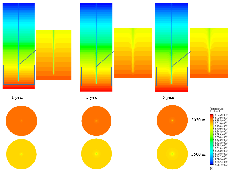
From the results presented in Figure 5, it can be seen that the soil temperature changes continuously during the transient phase (1st, 3rd, and 5th year). Due to the heat exchange between the soil and the U-tube BHE, the radius of thermal influence, defined here as the zone where rock temperature remains near-stable, gradually expands over time until a quasi-equilibrium is approached.
Figure 5. Contour plots of the ground over 1, 3 and 5 years of continuous operation at W = 0.5 m/s and T = 303.15 K
Initially, the isotherms are parallel to the surface and bend near the heat exchanger. Then, the radius of influence expands until it approaches an equilibrium state where the heat flux absorbed by the U-tube BHE is approximately balanced by the heat flux supplied by the surrounding rock.
In our simulations, the radius of influence stabilizes near ~75 m, a scale that is small relative to the reservoir diameter of 200 m. This is consistent with other parametric DBHE studies that report thermal influence zones of tens to a few hundred of meters depending on the thermal load and geological conditions [38, 39].
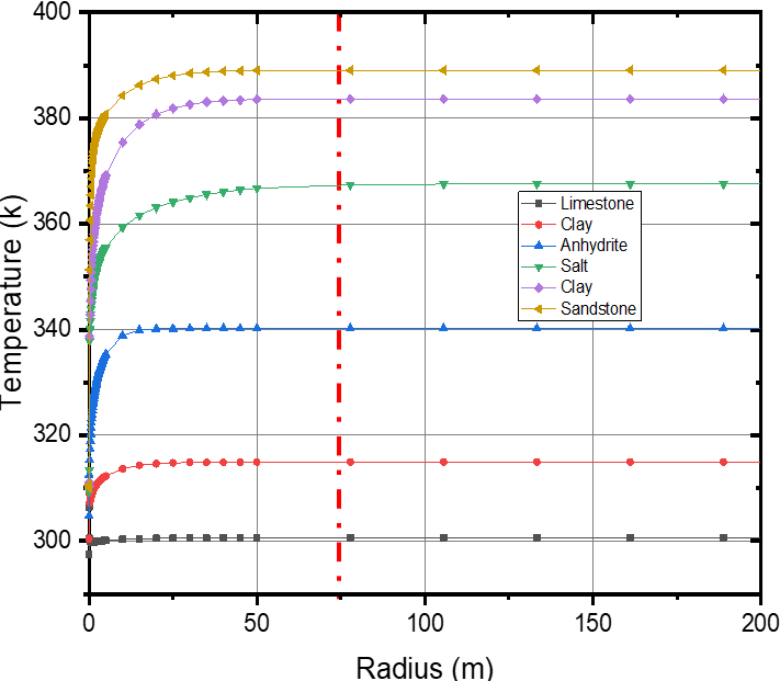
The temperature profiles of the soil layers over 5 years of operation (Figure 6) show that the temperature decrease around the well extends to about the computed radius (~75 m) and then remains nearly constant; this supports the choice of a computational domain larger than 200 m as adequate to avoid boundary effects in 5-year transient simulations.
Figure 6. Radial temperature profiles of the surrounding ground after 5 years of operation at W = 0.5 m/s and T = 288.15 K
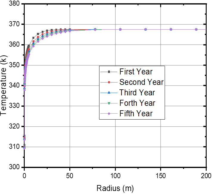
The temperature profiles of the surrounding rock at a depth of 2313 m observed during the first five years of operation (Figure 7) show that the rate of ground temperature decrease progressively slows, indicating that longer timescales are required to approach equilibrium.
Figure 7. Radial temperature profiles at 2313 m for different years of operation at W = 0.5 m/s and T = 288.1 K
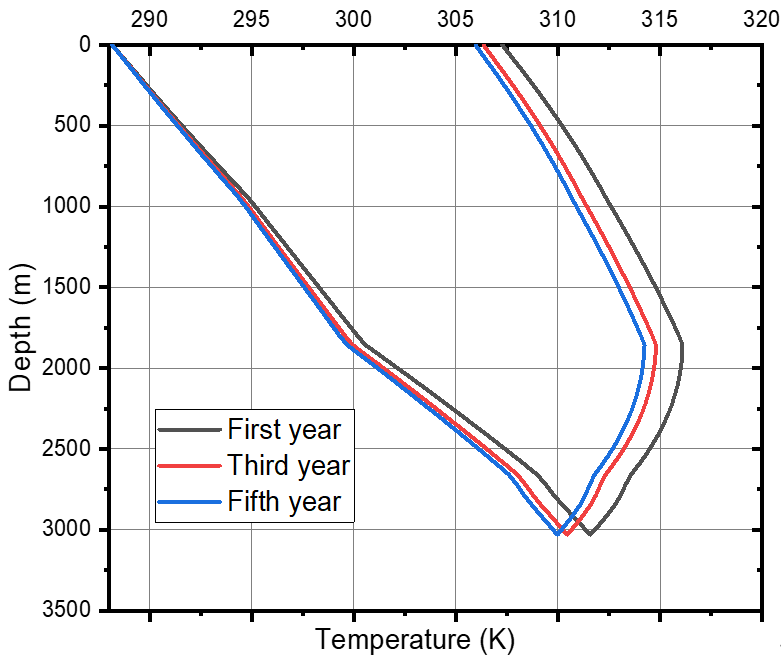
Figure 8 shows the temperature depth profile of the working fluid over several years of operation. It can be seen that the fluid outlet temperature decreases with time due to the cooling of the circulating water during the downflow; this reduction is explained by the diminishing temperature gradient between the formation and the working fluid, which reduces the convective heat transfer rate and the outlet temperature.
Figure 8. Vertical fluid temperature profiles along the U-tube BHE during 5 years of operations at W = 0.5 m/s and T = 288.15 K
In addition, it was observed that the maximum outlet temperature occurs during the first year of operation. After five years, the outlet temperature stabilizes near 306 K (Δ ≈ 3 ℃). Notably, the variation of the working fluid temperature with depth in the salt layer (1850-2776 m) during upflow is more pronounced than in other layers, due to the longer residence time of the fluid in that interval and the relatively high thermal conductivity of the salt formation, which enhances conductive heat transfer and increases the vertical temperature gradients.
3.2 Effect of working fluid injection velocity
Recent studies on deep U-tube and coaxial geothermal systems have shown that the injection velocity is one of the most influential operational parameters, directly affecting the outlet temperature, heat extraction rate, and long-term thermal depletion of the surrounding rock [40-42].
A crucial parameter to examine is the mass flow rate, which plays a key role in the heat exchanger between the soil and the BHE. The mass flow rate increases as the fluid inlet velocity increases according to Eq. (9).
$\dot{m}=\rho A U$ (9)
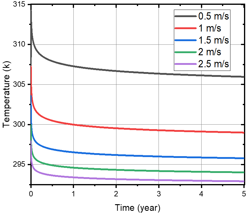
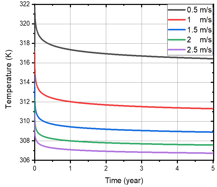
Figure 9 presents the impact of inlet flow velocity on outlet temperature for two inlet temperatures (288.15 K and 303.15 K). The outlet temperature decreases progressively with time, and this decrease becomes more pronounced at higher injection velocities, a behavior consistent with recent numerical simulations of deep geothermal wells showing that higher velocities accelerate the thermal drawdown of the subsurface [40]. Otherwise, Higher injection velocities also increase the cooling rate of the surrounding rock, which leads to an earlier decline in outlet temperature
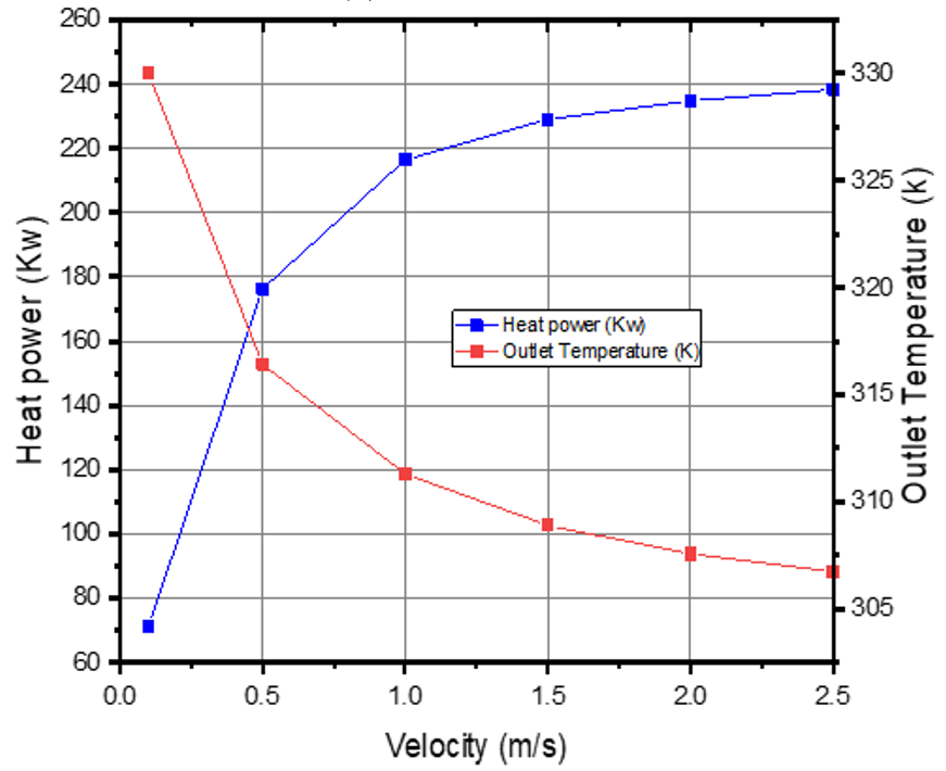
Moreover, the mass flow rate plays a significant role during the transient period: as the velocity increases, the outlet temperature decreases, as confirmed in Figure 10. This trend is largely attributed to the reduction in residence time, limiting the heat absorbed by the fluid as it travels up the well.
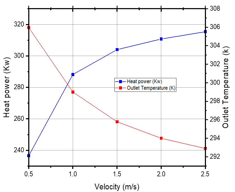
Figure 11 presents the results of simulations performed at different flow rates. Increasing the flow rate produces two contrasting effects: the heat extraction rate rises, while the outlet temperature decreases. The rise in heat extraction is expected, since it is directly proportional to the flow rate, as expressed in Eq. (10). However, higher flow rates also reduce the residence time of the fluid within the borehole, limiting the heat exchange with the surrounding rock and leading to lower outlet temperatures.
$Q_{ {ext }}=\dot{m} C_p\left(T_{ {out }}-T_{ {in }}\right)$ (10)
where, $\dot{m}$ is the mass flow rate, Cp is the specific heat capacity of the fluid, Tout is the outlet temperature of U-tube BHE, and Tin is the inlet temperature of the fluid.
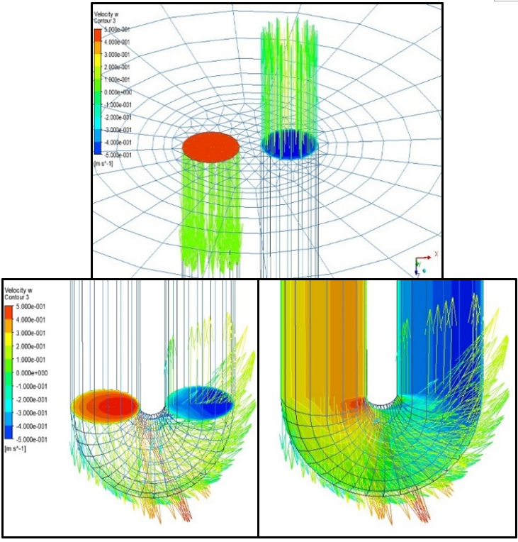
Figure 12 displays the colored velocity vectors as a function of velocity magnitude. A slight asymmetry can be observed between the velocities in the ascending and descending branches, likely caused by pressure losses or thermal dissipation during the flow. The transition at the U-tube bend (between the descending and ascending flow) highlights zones of recirculation or turbulence, which are typical of geothermal systems with this geometry. The velocity vectors and their direction are crucial for assessing the fluid flow and thermal performance of the heat exchanger [43]. This visualization highlights areas where the flow could be optimized to improve overall efficiency. For effective heat transfer, the flow velocity must be appropriately adjusted: excessively high velocities would increase pressure losses, while excessively low velocities would limit heat transfer.
Figure 12. Velocity vectors in the top and the elbow of the U-tube BHE
3.3 Effect of working fluid injection temperature
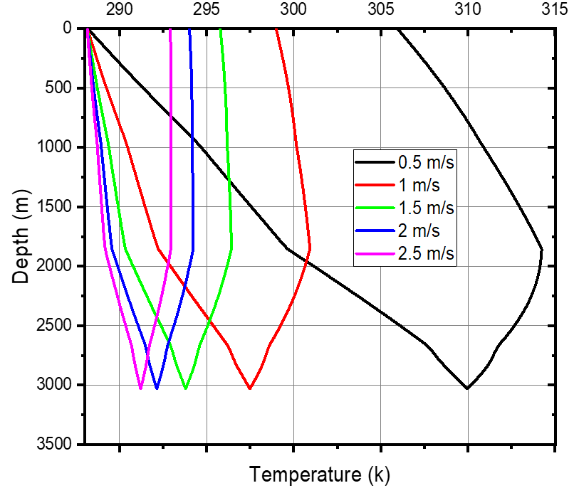
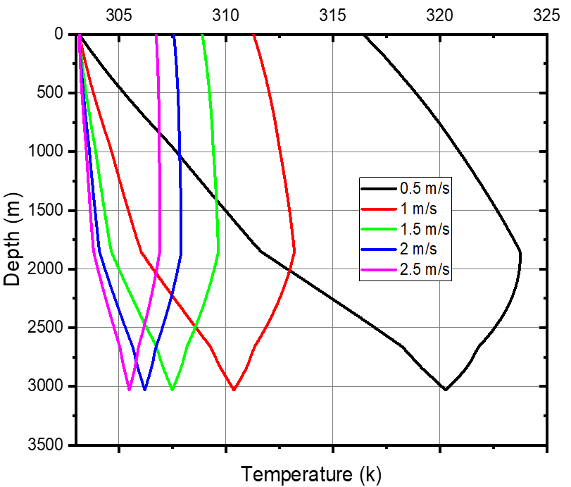
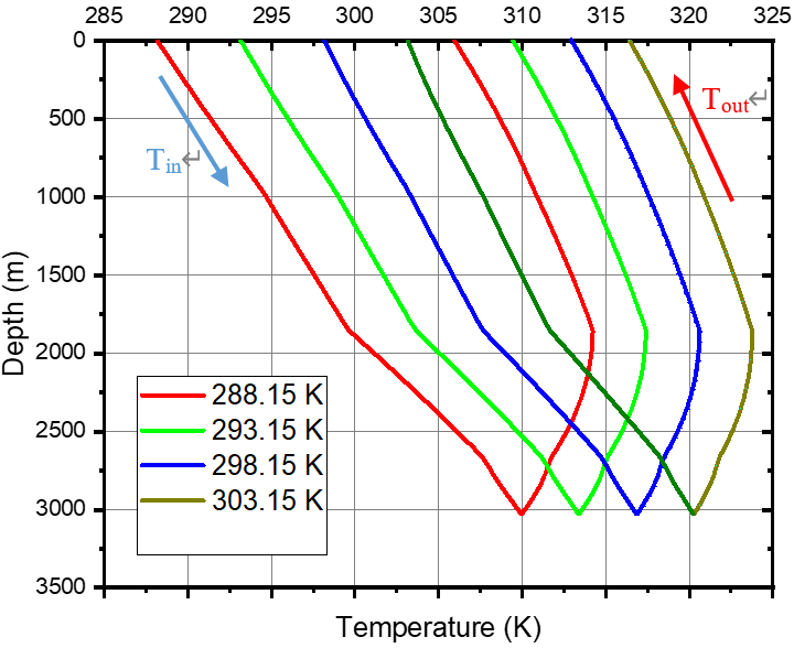
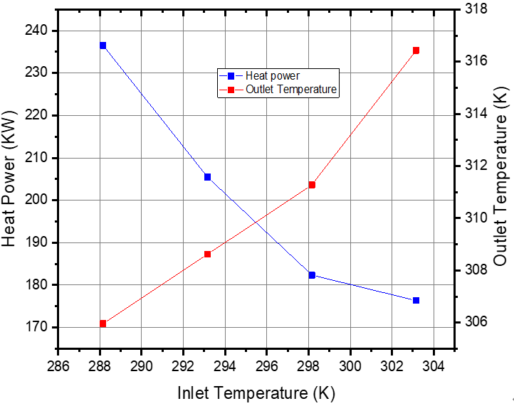
Operational inlet fluid temperature is a key parameter controlling the thermal behavior of BHEs, as it directly affects the driving temperature gradient between the heat source (ground) and working fluid. Recent numerical and experimental studies have shown that variations in inlet temperature can significantly influence outlet temperature trends and heat transfer rates over transient operation of geothermal systems [26, 44-46]. To highlight the effect of this parameter, several simulations were performed by increasing the inlet temperature from 288.15 K to 303.15 K with a fluid injection velocity of 0.5 m/s. Figures 13 and 14 show that the fluid outlet temperature increases almost linearly with the inlet temperature.
Figure 13. Effect of different inlet temperatures of the water at W = 0.5 m/s
Figure 14. Outlet temperature and heat power vs. inlet working fluid temperature after 5 years of continuous operation at W = 0.5 m/s
This behavior is consistent with recent modeling work that demonstrates strong sensitivity of outlet temperature to boundary conditions and operational parameters in deep borehole systems, where the initial thermal gradient sets the base driving force for heat uptake [44, 46].
Throughout this study, the soil surface temperature remains constant at 298 K. As long as the inlet temperature remains lower than the well bottom temperature, the outlet temperature will be higher than the inlet temperature, but the effective heat gain (Tout - Tin) decreases with higher Tin, reflecting reduced thermal drive.
Moreover, an increase in inlet temperature results in a decrease in temperature contrast between the inlet and outlet sections, leading to a reduction in instantaneous thermal power generated, because heat transfer scales with the temperature difference between fluid and formation. In fact, in the conducted simulations, a one-degree increase in the inlet temperature results in approximately a 0.6 K increase in outlet temperature. This sub-unit gain (less than 1:1 increase) is physically expected because heat transfer resistance in the fluid and surrounding rock limits the proportion of formation heat that can be transferred within finite residence time.
3.4 Effect of the length of the outlet pipe insulation
As mentioned above, the water temperature rises steadily in the downward direction due to the increasing temperature of the U-tube influenced by the geothermal gradient and the duration of contact between the fluid and the hot wall. Conversely, in the upward direction, the temperature of the grout decreases with depth until it falls below the temperature of the working fluid at a certain depth. This cooling in ascent is explained by the natural decrease in formation temperature with depth and by heat exchange between the ascending fluid and the cooler grout/formation. Insulating the outlet pipe reduces this axial heat loss and therefore helps preserve the fluid’s thermal energy gained in the downflow [47-49].
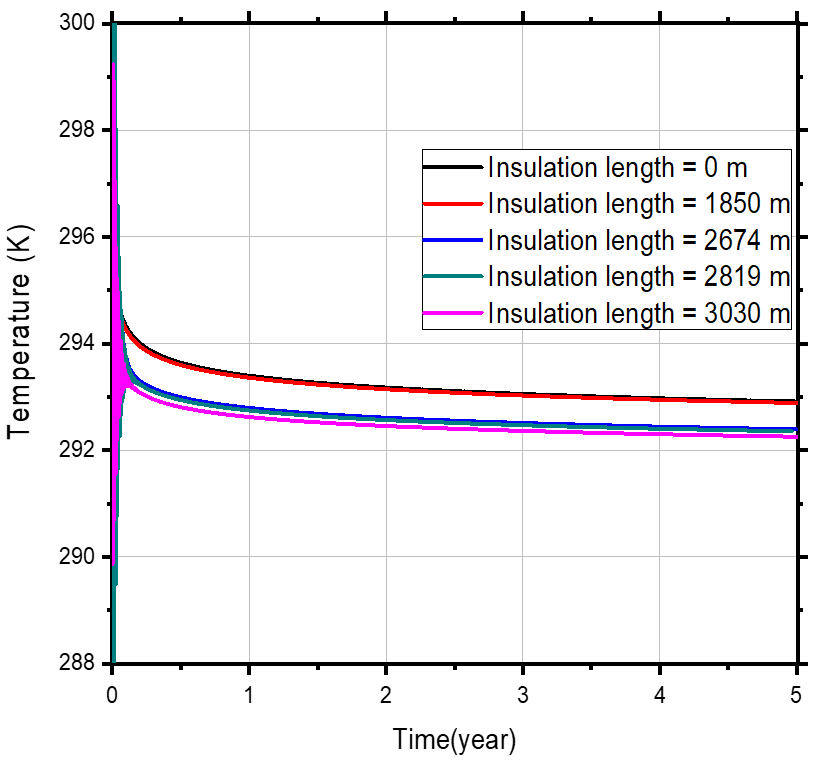
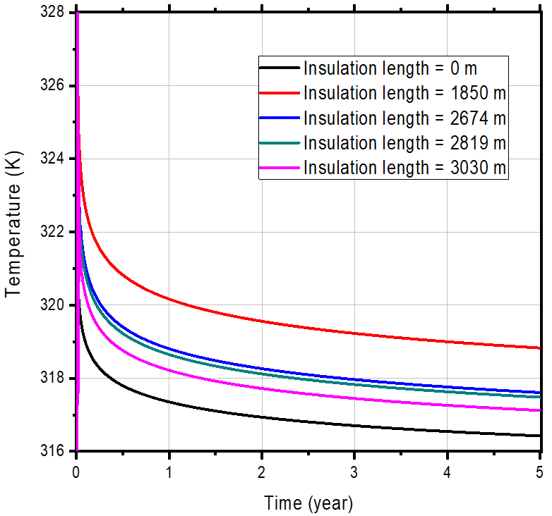
In this model, thermal insulation is provided by polystyrene, which has a thermal conductivity of 0.027 W/m·K. The simulations show that the heat exchanger reaches near-maximum outlet temperature and extraction performance when the insulated height is set to ≈1850 m; beyond this insulated length, additional gains in outlet temperature are small (diminishing returns). It can also be concluded that the optimum insulation height found (≈1850 m) is primarily a function of the well depth, the geothermal gradient, and the location of the largest ΔT along the riser and is therefore relatively insensitive to moderate changes in inlet velocity or inlet temperature in the parameter range tested (Figure 15).
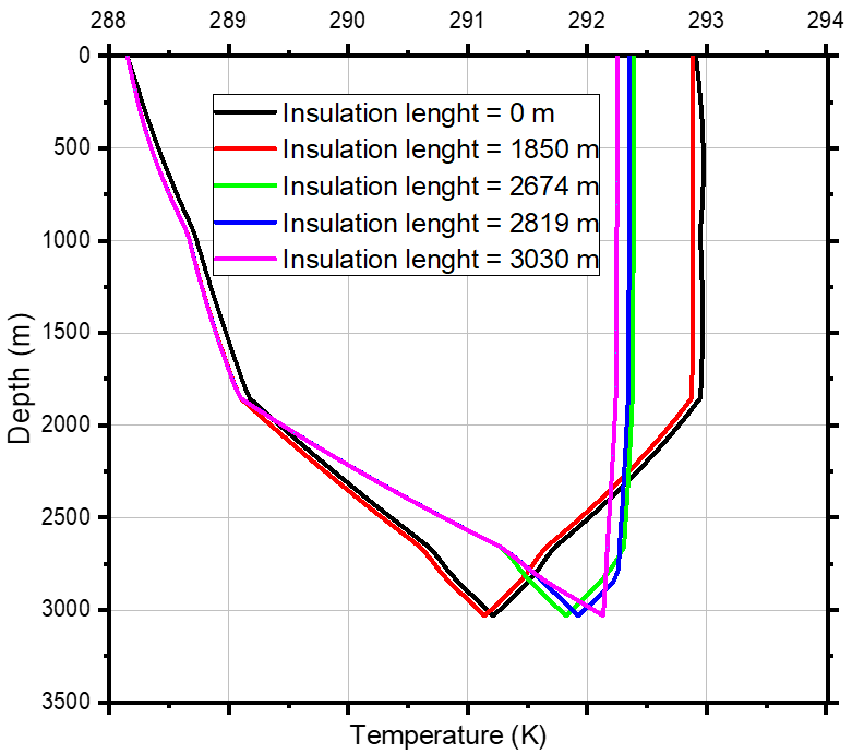
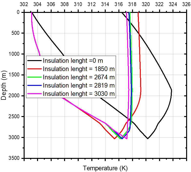
In addition, Figure 16 shows the temperature-depth profiles of the working fluid for two different input cases after 5 years of operation. Reducing the insulation length increases heat transfer from the ascending fluid to the grout, producing stronger cooling of the upflow. Conversely, without insulation, the downflow may be heated by upward conduction and axial interactions, producing the counter-intuitive cross-effect where the descending leg gains temperature while the ascending leg loses it. This phenomenon arises from the coupling of axial conduction in the grout and convective transport in the fluid mechanisms documented in recent parametric and experimental studies on DBHE [47, 48].
As shown in Figure 16(a), at high fluid velocity (2.5 m/s) the residence time is short, and the opportunity for convective heat transfer per unit length is limited; consequently, uninsulated riser sections produce smaller absolute losses than in low-velocity cases. In addition, the absence of insulation reduces the temperature difference between the ground and the circulating fluid, thus reducing local heat fluxes compared to insulated cases. Consequently, the high outlet velocity combined with short residence time reduces heat loss from the ascending fluid and results in only a slight temperature drop.
The fluid velocity shown in Figure 16(b) is much lower (0.5 m/s) than in the previous case. In this low-velocity regime, the residence time increases and the ascending fluid exchanges heat with the grout over a longer period; therefore, the absence of insulation produces a significant drop in the upflow temperature. As a result, the optimum insulation height computed here as ≈1850 m effectively balances insulation material use and thermal preservation across the expected range of operating velocities and inlet temperatures. This optimum will be used for the remainder of the study.
3.5 Effect of the pipe radius
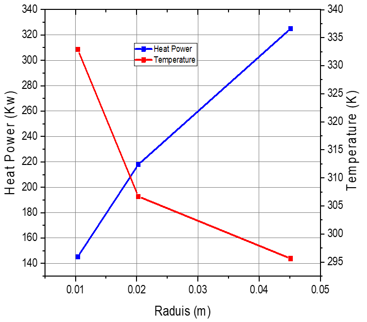
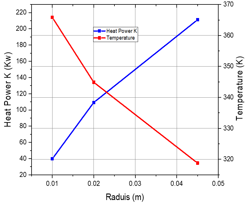
This section aims to analyze the effect of the radius of the BHE tube. Indeed, reducing the radius results in a lower mass flow rate and higher convective heat transfer coefficient at the wall, while increasing the temperature of the outlet fluid due to enhanced fluid-wall interaction and higher local ΔT conditions. Conversely, increasing the pipe radius lowers the working fluid temperature but can increase the overall amount of heat extracted, as a larger cross-section reduces flow resistance and enhances total energy extraction capacity.
In other words, increasing the pipe radius lowers the working fluid temperature but increases the amount of heat extracted from the abandoned oil well, as shown in Figure 17. The inverse relationship between outlet temperature and tube diameter in Figure 18 emerges because smaller radii promote stronger velocity gradients near the walls, increasing local convective coefficients at the expense of higher frictional losses. This explains why a smaller diameter may show a higher local Tout but a reduced net mass transport.
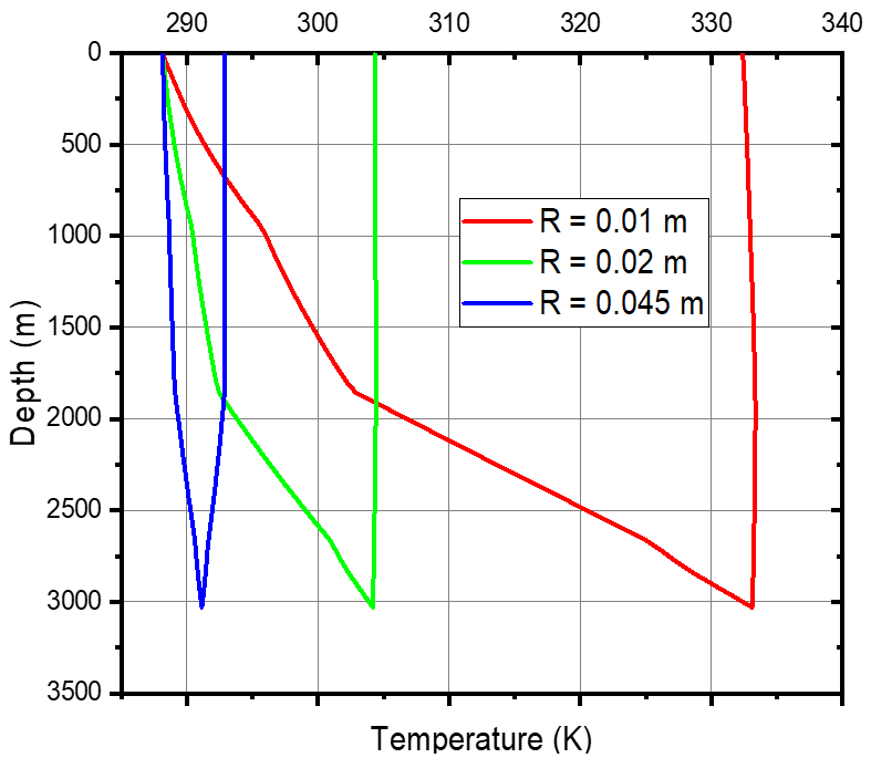
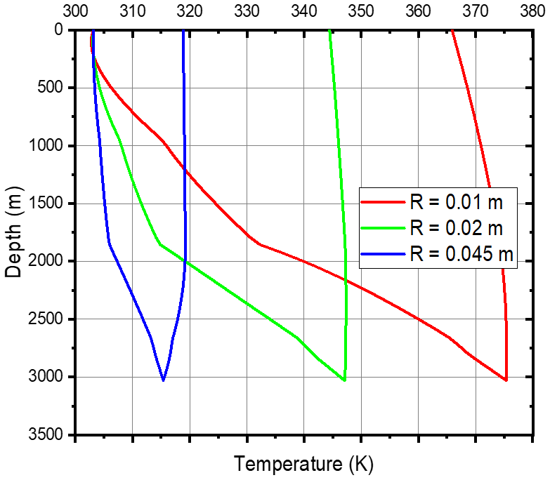
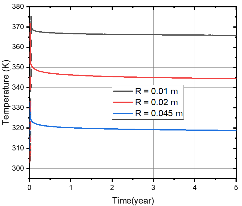
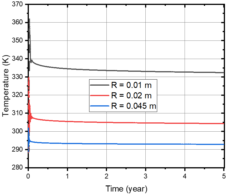
In addition, a slightly slower evolution of the temperature profile is observed in the inlet section for the inlet temperature of 303.15 K (Figure 18(b)), compared to the case at 288.15 K (Figure 18(a)). This behavior is consistent with the fundamental physics of convective heat transfer: when Tin is closer to the adjacent formation temperature, the local driving ΔT for conduction is reduced, causing slower changes in fluid temperature along the tube length. This trend has also been observed in other geometrical variation studies on U-tube and coaxial heat exchangers, where inlet conditions modulate longitudinal thermal gradients [9, 50].
When the soil temperature becomes higher than the working fluid temperature at a given depth, the direction of the net heat flux reverses (from fluid to formation), which affects the magnitude of outlet temperature change. For these reasons, the decrease and increase in fluid temperature are more pronounced in the smaller diameter pipe (e.g., 0.01 m) than in the larger diameter pipes, highlighting the interplay between tube radius, local Reynolds number, and convective heat transfer coefficients.
An even more remarkable fact, as shown in Figure 19, is that the fluid outlet temperature does not vary significantly over the five years of operation. This plateau in outlet temperature suggests that the system reaches a quasi-steady-state over long operational times, where the formation’s thermal properties and the borehole’s effective thermal resistance dominate the energy balance.
Such long-term plateauing behavior has been noted in DBHE simulations where diameter and geometry changes tend to affect initial transients more strongly than long-term equilibrium profiles [9, 39].
This indicates that the abandoned oil well studied in this paper can be used as a long-term geothermal resource, either for power generation or for direct applications using the U-tube heat exchanger, as the outlet temperature becomes relatively insensitive to small changes in tube radius once the system’s thermal field stabilizes over prolonged operation.
The objective of this paper was to develop a reliable simulation model to assess the feasibility of geothermal energy production from abandoned oil wells in the sedimentary basin of southeastern Algeria. A three-dimensional U-tube BHE model was constructed and simulated under transient conditions using ANSYS CFX to investigate heat transfer behavior within the well and predict the long-term thermal performance of the system. Real field data, including well geometry, geological layer properties, and the geothermal gradient, were integrated to ensure a realistic evaluation.
The results showed that the system stabilizes after approximately five years of continuous operation, as the decline in the surrounding soil temperature becomes negligible. For a depth of 3030 m, a diameter of 0.045 m, an inlet velocity of 0.5 m/s, and an inlet temperature of 30 ℃, simulations predicted an outlet temperature of about 43 ℃ after five years. The analysis also revealed that inlet velocity has a significant impact: higher velocities increase the gross heat output but reduce outlet temperature, while lower velocities have the opposite effect. In contrast, higher inlet temperature increases outlet temperature but slightly reduces heat extraction rate. Partial insulation of the upper ascending section where the fluid is warmer than the surrounding rock proved beneficial, improving outlet temperature and showing an optimal insulation length that remains nearly constant regardless of the flow rate or inlet temperature. The impact of BHE diameter was also assessed, indicating that smaller diameters raise outlet temperature but reduce the total heat extraction. Overall, the model suggests a maximum gross thermal output of 39.45 kW for the studied well, corresponding to a geothermal gradient of 31.1 ℃/km.
Beyond these numerical results, the study demonstrates that repurposed deep wells can provide stable thermal output over several years and that operational parameters such as inlet velocity, inlet temperature, diameter, and insulation configuration critically affect system performance. The predicted outlet temperatures also indicate that such systems can potentially supply low-temperature power generation technologies, particularly ORC systems, enabling small-scale electricity production in remote oilfield regions.
Despite its strengths, the model presents several limitations linked primarily to operational simplifications. The simulations neglect variable mass-flow control, long-term fouling and operational cycling, all of which may influence real-world behavior. These aspects should be considered in future refinements.
Further research could expand the model by examining alternative borehole geometries, especially coaxial heat exchangers, which may enhance system performance depending on geological conditions. Future work should also incorporate thermo-hydro-mechanical coupling, quantify parameter uncertainty, and evaluate operational variability over long periods. Additional studies on multi-well interactions, working-fluid optimization, and economic assessment would help establish the feasibility of deploying geothermal repurposing strategies across North African sedimentary basins.
|
A |
Cross sectional surface (m2) |
|
a |
Geothermal gradient (C/m) |
|
DBHE |
Deep Borehole Heat Exchanger |
|
BHE |
Borehole Heat Exchanger |
|
b |
Surface temperature (C) |
|
C |
Specific heat (J/kg·K) |
| COP | Coefficient Of Performance |
|
C1 |
Constant used in the standard k-є model |
|
C2 |
Constant used in the standard k-є model |
|
Cμ |
Constant used in the standard k-є model |
|
k |
Turbulent kinetic energy (m2/s2) |
|
ṁ |
Mass flow rate (kg/s) |
|
Pk |
Production term for k |
|
Qext |
Heat power (W) |
| ORC | Organic Rankine Cycle |
|
R |
Pipe radius (m) |
|
T |
Temperature (K) |
|
Tin |
Inlet temperature of the fluid (K) |
|
Tout |
Outlet temperature of the fluid (K). |
|
$\vec{U}$ |
Fluid velocity vector (m/s) |
|
W |
Fluid velocity (m/s) |
|
Z |
The formation depth (m) |
|
Greek Letters |
|
|
α |
Thermal diffusivity (m2/s) |
|
∆t |
Time step (second) |
|
∆z |
Grid step (m) |
|
ϵ |
Dissipation rate of turbulent kinetic energy (m2/s) |
|
λ |
Thermal conductivity (W/m K) |
|
μ |
Molecular dynamic viscosity (Pa s) |
|
μt |
Turbulent viscosity (Pa s) |
|
ρ |
Density (kg /m3) |
|
σk |
Diffusion coefficient for k |
|
σϵ |
Diffusion coefficient for ϵ |
[1] Renaud, H., Verdin, P., Falcone, G. (2019). Numerical simulation of a deep borehole heat exchanger in the Krafla geothermal system. International Journal of Heat and Mass Transfer, 143: 118496. https://doi.org/10.1016/j.ijheatmasstransfer.2019.118496
[2] Energy Information Administration (EIA). (2022). Geothermal energy and the environment. https://www.eia.gov/energyexplained/geothermal/geothermal-energy-and-the-environment.php, accessed on Nov. 14, 2024.
[3] International Energy Agency (IEA). (2023). The future of geothermal energy. Paris, International Energy Agency, pp. 1-125. https://iea.blob.core.windows.net/assets/b46f9bee-0c32-4a59-ba95-546530004173/TheFutureofGeothermal.pdf.
[4] Williams, J.P., Regehr, A., Kang, M. (2021). Methane emissions from abandoned oil and gas wells in Canada and the United States. Environmental Science & Technology, 55(5): 3449. https://doi.org/10.1021/acs.est.1c00377
[5] Alimonti, C., Soldo, E. (2016). Study of geothermal power generation from a very deep oil well with a wellbore heat exchanger. Renewable Energy, 86: 292-301. https://doi.org/10.1016/j.renene.2015.08.031
[6] Xia, Z.H., Qin, S.Y., Tao, Z.Y., Jia, G.S., Cheng, C.H., Jin, L.W. (2023). Multi-factor optimization of thermo-economic performance of coaxial borehole heat exchanger geothermal system based on Levelized Cost of Energy analysis. Renewable Energy, 219: 119513. https://doi.org/10.1016/j.renene.2023.119513
[7] Beckers, K.F., Rangel-Jurado, N., Chandrasekar, H., Hawkins, A.J., Fulton, P.M., Tester, J.W. (2022). Techno-economic performance of closed-loop geothermal systems for heat production and electricity generation. Geothermics, 100: 102318. https://doi.org/10.1016/j.geothermics.2021.102318
[8] Liu, S., Taleghani, A.D., Ji, K. (2024). An advanced closed-loop geothermal system to substantially enhance heat production. Energy Conversion and Management, 322: 119168. https://doi.org/10.1016/j.enconman.2024.119168
[9] Gharibi, S., Mortezazadeh, E., Aghcheh Bodi, S.J.H., Vatani, A. (2018). Feasibility study of geothermal heat extraction from abandoned oil wells using a U-tube heat exchanger. Energy, 153: 554-567. https://doi.org/10.1016/j.energy.2018.04.003
[10] Hu, X.C., Banks, J., Guo, Y.T., Liu, W.V. (2021). Retrofitting abandoned petroleum wells as doublet deep borehole heat exchangers for geothermal energy production-a numerical investigation. Renewable Energy, 176: 115-134. https://doi.org/10.1016/j.renene.2021.05.061
[11] Pokhrel, S., Sasmito, A.P., Sainoki, A., Tosha, T., Tanaka, T., Nagai, C., Ghoreishi-Madiseh, S.A. (2022). Field-scale experimental and numerical analysis of a downhole coaxial heat exchanger for geothermal energy production. Renewable Energy, 182: 521-535. https://doi.org/10.1016/j.renene.2021.10.038
[12] Chappidi, S., Kumar, A., Singh, J. (2023). Geothermal energy extraction from abandoned oil and gas wells using mono and hybrid nanofluids. Geothermics, 114: 102794. https://doi.org/10.1016/j.geothermics.2023.102794
[13] Cai, X.L., Liu, Z.W., Xu, K., Li, B.Z., Yang, M.H. (2024). Numerical simulation on converting abandoned wells into double-well open-loop geothermal system. Applied Thermal Engineering, 248: 123324. https://doi.org/10.1016/j.applthermaleng.2024.123324
[14] Davoodi, S., Al-Shargabi, M., Wood, D.A., Slivkin, S., Shishaev, G., Rukavishnikov, V.S. (2024). Geothermal energy recovery from abandoned petroleum wells: A review of the challenges and opportunities. Sustainable Energy Technologies and Assessments, 68: 103870. https://doi.org/10.1016/j.seta.2024.103870
[15] Beier, R.A. (2020). Thermal response tests on deep borehole heat exchangers with geothermal gradient. Applied Thermal Engineering, 178: 115447. https://doi.org/10.1016/j.applthermaleng.2020.115447
[16] Kimiaei, S., Kazemi-Ranjbar, S., Jalali, A., Ahmadi, P. (2022). A novel three-dimensional numerical model to simulate heat transfer inside a double U-tube borehole with two independent circuits. International Journal of Heat and Mass Transfer, 184: 122243. https://doi.org/10.1016/j.ijheatmasstransfer.2021.122243
[17] Fang, L., Diao, N.R., Fang, Z.H., Zhu, K., Zhang, W.K. (2017). Study on the efficiency of single and double U-tube heat exchangers. Procedia Engineering, 205: 4045-4051. https://doi.org/10.1016/j.proeng.2017.09.881
[18] Yu, C., Zhang, Y.Q., Tan, Y.W., Song, X.Z., Shi, Y., Wang, G.S., Huang, H.C. (2022). Performance comprehensive evaluation of downhole heat exchanger geothermal systems with various configurations and working fluids. Applied Thermal Engineering, 213: 118745. https://doi.org/10.1016/j.applthermaleng.2022.118745
[19] Kerme, E.D., Fung, A.S., Leong, W.H. (2024). Analysis of the combined effect of major influencing parameters for designing high-performance single (sBHE) and double (DBHE) U-tube borehole heat exchangers. Energies, 17: 2525. https://doi.org/10.3390/en17112525
[20] Welsch, B., Göllner-Völker, L., Schulte, D.O., Bär, K., Sass, I., Schebek, L. (2018). Environmental and economic assessment of borehole thermal energy storage in district heating systems. Applied Energy, 216: 73-90. https://doi.org/10.1016/j.apenergy.2018.02.011
[21] Śliwa, T., Gołaś, A., Wołoszyn, J., Gonet, A. (2012). Numerical model of borehole heat exchanger in Ansys CFX software. Archives of Mining Sciences, 57(2): 375-390. https://doi.org/10.2478/v10267-012-0024-3
[22] Rees, S.J., He, M.M. (2013). A three-dimensional numerical model of borehole heat exchanger heat transfer and fluid flow. Geothermics, 46: 1-13. https://doi.org/10.1016/j.geothermics.2012.10.004
[23] Cheng, W.L., Li, T.T., Nian, Y.L., Wang, C.L. (2013). Studies on geothermal power generation using abandoned oil wells. Energy, 59: 248-254. https://doi.org/10.1016/j.energy.2013.07.008
[24] Kharseh, M., Al-Khawaja, M., Hassani, F. (2019). Optimal utilization of geothermal heat from abandoned oil wells for power generation. Applied Thermal Engineering, 153: 536-542. https://doi.org/10.1016/j.applthermaleng.2019.03.047
[25] Gao, Q., Han, Z.X., Han, Y.H., Zhou, D.S., Ghassemi, A., Yu, H.G. (2025). Numerical study on heat extraction performance and parameter optimization of a U-shaped geothermal well. Journal of Petroleum Exploration and Production Technology, 15: 10225. https://doi.org/10.1007/s40948-025-01022-5
[26] Matyska, C., Zábranová, E. (2023). Heat extraction calculations for deep coaxial borehole heat exchangers: Matrix analytical approach. Geophysical Journal International, 235(3): 2323-2338. https://doi.org/10.1093/gji/ggad367
[27] Alimonti, C. (2023). Technical performance comparison between U-shaped and deep borehole heat exchangers for closed-loop geothermal energy. Energies, 16(3): 1351. https://doi.org/10.3390/en16031351
[28] Ma, Y.Y., Li, S.B., Zhang, L.G., Liu, S.Z., Wang, M. (2023). Heat extraction performance evaluation of U-shaped well geothermal production system under different well-layout parameters and engineering schemes. Renewable Energy, 203: 473-484. https://doi.org/10.1016/j.renene.2022.12.082
[29] Heim, E., Stoffel, P., Düber, S., Knapp, D., Kümpel, A., Müller, D., Klitzsch, N. (2024). Comparison of simulation tools for optimizing borehole heat exchanger field operation. Geothermal Energy, 12: 64. https://doi.org/10.1186/s40517-024-00303-8
[30] Szklarz, S.P., Barros, E.G.D., Khoshnevis Gargar, N., Peeters, S.H.J., van Wees, J.D., van Pul-Verboom, V. (2024). Geothermal field development optimization under geomechanical constraints and geological uncertainty: Application to a reservoir with stacked formations. Geothermics, 123: 103094. https://doi.org/10.1016/j.geothermics.2024.103094
[31] Zeng, Z., Shen, W.J., Wang, M.C., Li, Z.Y., Wang, X.Y., Ding, J.H. (2024). Numerical simulation of multi-field coupling in geothermal reservoir heat extraction of enhanced geothermal systems. Journal of Petroleum Exploration and Production Technology, 14: 1631-1642. https://doi.org/10.1007/s13202-024-01775-x
[32] Chong, Q.W., Wang, JY., Gates, I.D. (2022). Evaluation of closed-loop U-Tube deep borehole heat exchanger in the Basal Cambrian Sandstone formation, Alberta, Canada. Geothermal Energy, 10: 21. https://doi.org/10.1186/s40517-022-00229-z
[33] Hamza, S., Fouad, B., Sofiane, A., Abdelkader, F., Daniela, B., Messaoud, B. (2024). Geological context and thermo-economic study of an indirect heat ORC geothermal power plant for the northeast region of Algeria. Energy, 290: 130323. https://doi.org/10.1016/j.energy.2024.130323
[34] Aliouane, L., Ouadfeul, S.A. (2023). Geothermal energy in Algeria and the contribution of geophysics. Physical Sciences Forum, 6(1): 2. https://doi.org/10.3390/psf2023006002
[35] Eskilson, P., Claesson, J. (1988). Simulation model for thermally interacting heat extraction boreholes. Numerical Heat Transfer, 13(2): 149-165. https://doi.org/10.1080/10407788808913609
[36] El-Said, E.M.S., Sharaf, M.A., Aljabr, A., Marzouk, S.A. (2024). Enhancing the performance of an earth air heat exchanger with novel pipe configurations. International Journal of Heat and Fluid Flow, 110: 109630. https://doi.org/10.1016/j.ijheatfluidflow.2024.109630
[37] Zhao, P., Li, X.Z., Zhang, D.H., Lin, Y.Z., Zhang, Y., Ji, Y.K. (2023). Numerical investigation of vertical borehole heat exchanger heat transfer under coupled conditions of groundwater seepage and layered subsurface. Geomechanics and Geophysics for Geo-Energy and Geo-Resources, 9: 33. https://doi.org/10.1007/s40948-023-00571-x
[38] Li, J., Xu, W., Li, J.F., Huang, S., Li, Z., Qiao, B., Yang, C., Sun, D.Y., Zhang, G.Q. (2021). Heat extraction model and characteristics of coaxial deep borehole heat exchanger. Renewable Energy, 169: 738-751. https://doi.org/10.1016/j.renene.2021.01.036
[39] Gascuel, V., Raymond, J., Rivard, C., Marcil, J.S., Comeau, F.A. (2022). Design and optimization of deep coaxial borehole heat exchangers for cold sedimentary basins. Geothermics, 105: 102504. https://doi.org/10.1016/j.geothermics.2022.102504
[40] Brown, C.S., Kolo, I., Banks, D., Falcone, G. (2024). Comparison of the thermal and hydraulic performance of single U-tube, double U-tube and coaxial medium-to-deep borehole heat exchangers. Geothermics, 117: 102888. https://doi.org/10.1016/j.geothermics.2023.102888
[41] Pan, S., Kong, Y.L., Chen, C.F., Pang, Z.H., Wang, J.Y. (2020). Optimization of the utilization of deep borehole heat exchangers. Geothermal Energy, 8: 42. https://doi.org/10.1186/s40517-020-0161-4
[42] Morchio, S., Beier, R.A. (2025). Modelling the U-pipe heat exchanger to estimate the borehole thermal resistances from distributed thermal response test data. Geothermics, 132: 103408. https://doi.org/10.1016/j.geothermics.2025.103408
[43] Benyoub, M., Aour, B., Bouhacina, B., Sadek, K. (2018). Numerical investigation of the physical properties effect on the thermal performance of a vertical geothermal heat exchanger. Engineering, Technology & Applied Science Research, 8(2): 2715-2723. https://doi.org/10.48084/etasr.1827
[44] Du, D.S., Li, Y.Q., Wang, K.P., Zhao, Y.Z., Hu, Z.Y., Zhang, W.D., Wang, Q.L. (2023). Experimental and numerical simulation research on heat transfer performance of coaxial casing heat exchangers in deep geothermal wells in Weihe Basin. Geothermics, 109: 102658. https://doi.org/10.1016/j.geothermics.2023.102658
[45] Chen, H., Tomac, I. (2023). Technical review on coaxial deep borehole heat exchanger. Geomechanics and Geophysics for Geo-Energy and Geo-Resources, 9: 84. https://doi.org/10.1007/s40948-023-00659-4
[46] Sui, D., Wiktorski, E., Røksland, M., Basmoen, T.A. (2019). Review and investigations on geothermal energy extraction from abandoned petroleum wells. Journal of Petroleum Exploration and Production Technology, 9: 1135-1147. https://doi.org/10.1007/s13202-018-0535-3
[47] Zhang, Q.X., Lu, F.Y., Huang, Y., Tan, L.W., Luo, J., Duan, L.C. (2025). Thermal performance of deep borehole heat exchangers (DBHEs) installed in a groundwater-filled hot dry rock (HDR) well in Qinghai, China. Energies, 18: 2229. https://doi.org/10.3390/en18092229
[48] Jia, Y.Y., Fang, Z.W., Zhao, Y.X., Liu, X.Y. (2022). Optimal insulation backfill depth analysis of coaxial deep borehole heat exchanger based on multi-factor orthogonal experiments. Energy and Buildings, 273: 112414. https://doi.org/10.1016/j.enbuild.2022.112414
[49] Luo, Y.Q., Xu, G.Z., Yan, T. (2020). Performance evaluation and optimization design of deep ground source heat pump with non-uniform internal insulation based on analytical solutions. Energy and Buildings, 229: 110495. https://doi.org/10.1016/j.enbuild.2020.110495
[50] Zhou, A.Z., Huang, X.W., Wang, W., Jiang, P.M., Li, X.W. (2021). Thermo-hydraulic performance of U-tube borehole heat exchanger with different cross-sections. Sustainability, 13: 3255. https://doi.org/10.3390/su13063255