Salah H. Abid Aun![]() | Safaa A. Ghadhban
| Safaa A. Ghadhban![]() | Kifah H. Hilal
| Kifah H. Hilal![]() | Issa Omle*
| Issa Omle*![]()
© 2025 The authors. This article is published by IIETA and is licensed under the CC BY 4.0 license (http://creativecommons.org/licenses/by/4.0/).
OPEN ACCESS
In this study, inclined baffles are employed to enhance heat transfer in double-stepped sudden expansion ducts by promoting the turbulent effect. Expansion ducts with various baffle configurations are suggested and investigated numerically by using ANSYS Fluent 20 R2. The temperature distribution, pressure drop, and velocity profile of the flow field in diverse cases are demonstrated to assess the effects of expansion ratio, baffle length, and baffle angle on the heat transfer between air and ducts. Results indicate that utilizing the baffles reduces the temperature gradient along the ducts, in which the corner temperature decreases by about 20℃. The heat transfer is improved, as well as the expansion ratio changes from 1.5–2 to 2–3 because of larger and more intense vortices. Increasing the baffle angle to 30° creates a region between the baffle and the corner as a jet that increases the velocity of air and heat transfer. At baffle distance (S) = 15 cm, the increment in average Nu is 35.8% at baffle angle = 30° compared with the result at baffle angle = 0. Validation of the computational results with previous research indicates good agreement with an error range between 5.8% and 12.3% for the case without a baffle due to variations in test conditions.
heat transfer enhancement, multi-step, sudden expansion, inclined baffles, fluid flow, CFD
Many engineering systems, such as industrial furnaces, solar energy storage, and air conditioning, require efficient design for convective heat transfer performance whilst keeping a low pressure difference. Different techniques, such as the utilization of nanofluids, porous media, and extrude baffles, have been widely used to enhance heat transfer in different applications [1-4]. For instance, many ways are employed to enhance heat transfer in sudden expansion (SE) ducts. These ways may be active or passive methods and can be found in different thermal systems, such as combustion chambers, power plants, heat exchangers, nuclear reactors, and electronic devices [5]. In the SE configuration, flow separation occurs, whilst recirculation flow results in proper heat transfer performance near the steps of expansion [6-9]. Many researchers have numerically and experimentally investigated the factors affecting heat transfer and fluid flow in SE configuration, such as expansion ratio (ER), Reynolds number, step height, duct geometry (circular or rectangular), and heating condition on SE surfaces (constant surface temperature or constant heat flux) [10-13]. The improvement of heat transfer performance depends on the increase in turbulence phenomena; consequently, increasing the mixing of fluid flow results in improved heat transfer, which can be achieved using baffles [14, 15]. Baffles with a suitable size and location may be utilized as an effective technique for this purpose.
Mushatet [16] numerically simulated forced convection in an SE duct with multiple baffles mounted on its lower surface. The effects of step height and baffle thickness on the thermal and flow fields of the fluid domain were investigated. Increasing Reynolds number and step height was determined to increase heat transfer and decrease the recirculation region size with reattachment length after the baffles. Heshmati et al. [17] numerically investigated the forced convection heat transfer in an SE duct with vertical baffles on the upper surface. Solid and slotted baffles with two ERs (2, 3) were utilized. The solid baffles with an ER of 2 achieved a 33% higher skin friction rate and 63% higher Nusselt number. The effects of baffle configurations such as shape, arrangement, size, step, and number have been reported numerically by Boruah et al. [18]. They indicated that the reattachment length decreased with the employment of baffles, and an increase in vortex size and the maximum local Nusselt number were observed close to the baffles due to the abrupt drop in temperature in this area. Meanwhile, a comparison of oscillating and stationary fins installed on the top surface of an SE duct was provided by Kumar and Vengadesan [19]. The oscillating fin indicated a higher average Nusselt number and lower pressure drop. Convective heat transfer through a 1:3 axisymmetric SE duct with and without baffles was numerically investigated by Saha et al. [20]. The value of the average Nusselt number was found to be 1.11 and 1.2 times for one and three baffles installed on the upper surface, respectively, compared with that in the no-baffle case.
Alqahtani et al. [21] evaluated the effect of the hole position of a perforated baffle on the top surface of an SE duct. Tests showed enhancements in heat transfer rate and flow pattern. The main flow passed through the zone between the duct surface and baffles, whilst the secondary flow was through baffle holes, which led to well-developed recycling cells as vortices. The best heat transfer rate was achieved in the case with a baffle hole far from the SE surface.
The research reviewed above is concerned with single SE ducts. However, in recent years, the focus has shifted to stepped SE, which has been performed in the automotive and marine industries [22, 23]. Wang et al. [22] numerically investigated the characteristics of fluid flow in a stepped SE. The ratio of distance between steps to step height was varied from 0 to 10. As the ratio increased, the primary recirculation region behind the two steps fully separated and reattached before the step ends. Furthermore, the first step vortex had less effect on the second step vortex. Oztop et al. [24] numerically analysed the turbulent flow of air in a stepped SE duct with a rectangular obstacle before the step to enhance heat transfer. The parameters investigated were the obstacle ratio varied between 0.25 to 1, and the step ratio, which ranged from 0.5 to 0.75. The highest Nusselt number was observed at an obstacle ratio of 1. Increasing the step ratio increased vortices, resulting in enhanced heat transfer. The same results were obtained by Togun et al. [25] for a similar configuration but without obstacles. Abdulrazzaq et al. [26] numerically studied promoting heat transfer over stepped SE with three types of working fluid, namely, water, ammonia, and ethylene glycol, and varying ratios of the first step height to the second step height of 0.5, 1, and 2. The simulation indicated that a higher Reynolds number led to a higher Nusselt number. The local Nusselt number was higher in cases 1 and 3 than in case 2 for all fluids. Mohankumar and Prakash [27] numerically investigated enhancing heat transfer along the corner zone of a double-stepped SE duct by employing two obstacles located in front of the step corner at Reynolds numbers ranging from 300 to 1000. The reattachment lengths after the first and second steps decreased in the obstacle cases, resulting in an enhanced local Nusselt number. Many related studies have been conducted, which used different techniques to enhance heat transfer in double-stepped SE, such as jet impingement [28] and magnetic field [29]. Kanna et al. [30] numerically studied the effects of the position and size of a circular cylinder as an obstacle in a double forward facing step in laminar and turbulent conditions. The results indicated that the Nusselt number was enhanced when the obstacle was located near the upper wall rather than the lower wall. Jahin et al. [31] simulated the heat transfer of hybrid Al2O3–Cu through backward facing step heating with constant heat flux on the lower surface. The Nusselt number increased with Reynolds number (500-800) and volume fraction (0.01-0.04). Alsabery et al. [32] numerically investigated enhancing heat transfer in backward facing step in three ways: waving the lower step surface, padding the wavy surface with porous media, and using alumina nanoparticle fluid. The results showed that the Nusselt number increased by 63% on the wavy surface compared with that on the flat surface and by 6.3% when the concentration of nanoparticles was varied from 0% to 4%.
Promising ways to improve heat transfer characteristics through a duct include the use of multi-stepped SE geometries with suitable baffles. This study aims to highlight the effects of multi-stepped SE ducts with different inclined baffle configurations associated with three main parameters, namely, baffle length, angle, and location, as well as ER, on convective heat transfer. Whereas previous studies focused on single-stepped SE ducts with right-angled baffles. A simulation model is developed to characterize the SE duct model using two different ERs (1.5-2 and 2-3). The duct is provided with two inclined baffles installed on its top surface. The patterns of temperature distribution, pressure contour, and velocity streamlines are analysed to study the influence of the baffle configuration in comparison with that of an SE duct without a baffle and identify the most effective design for heat transfer augmentation.
2.1 Problem formulation
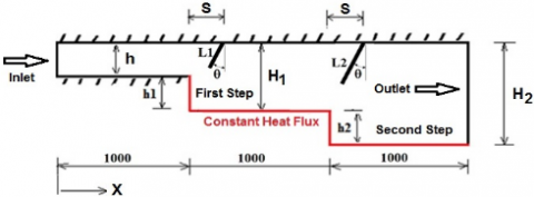
This numerical study utilized a geometric model that involved a stepped SE duct with a thin baffle that had different configurations of length, position, and angle. The design of the model dimensions was based on a former study [8]. The duct dimensions and general baffle configuration are shown in Figure 1. The length, position, and angle of the baffle were proposed to be suitable for to duct dimensions. The entrance and top surface of the duct were thermally insulated, whilst the bottom surface and steps were subjected to a constant heat flux (q’’ = 1500 W/m2). The two-dimensional model of the duct had an upstream length (L) of 1000 mm for each step and an entrance height (h) of 250 mm.
Figure 1. Schematic of the SE duct (dimensions in mm)
The ER represents the ratio between the height of the duct after expansion (downstream section) and the height before expansion (upstream section). It characterizes the extent of geometric enlargement in the flow domain and has a significant influence on flow separation, recirculation behavior, and overall heat transfer performance. The ER is mathematically defined as:
For the first step: ER = H1/h
And for the second step: ER = H2/h
Two cases of ERs were investigated, as detailed in Table 1.
Table 1. Duct dimensions (in mm) for the two ER cases
|
ER |
h |
H1 |
H2 |
h1 |
h2 |
L1 |
L2 |
S (variable) |
|
1.5-2 |
250 |
375 |
500 |
125 |
125 |
175 |
233 |
150, 250, 350 |
|
2-3 |
250 |
500 |
750 |
250 |
250 |
233 |
350 |
150, 250, 350 |
The effect of baffle angle (⍬) with values of 0°, 20°, and 30° was examined. The two-dimensional model of double-stepped SE duct geometry was arranged using the Gambit software.
2.2 Governing equations
The governing equations of the model rely on a two-dimensional flow, considering air as a working fluid. This study assumed a steady-state, incompressible, homogenous, fully developed, and turbulent flow. The Navier–Stokes equations govern the air flow and the heat transfer phenomena in the duct domain. The continuity, momentum, and energy equations were simulated and discretized using the standard k-epsilon (k–ε) and SIMPLE algorithm, gathered with the finite volume method. The governing equations are detailed as follows [25, 27, 33].
Continuity equation:
$\frac{\partial u}{d x}+\frac{\partial v}{d y}=0$ (1)
Momentum equations are formed in x and y axes, as below:
$\rho_f\left(u \frac{\partial u}{\partial x}+v \frac{\partial u}{\partial y}\right)=-\frac{\partial P}{\partial x}+\mu_f\left(\frac{\partial^2 u}{\partial x^2}+\frac{\partial^2 u}{\partial y^2}\right)$ (2)
$\rho_f\left(u \frac{\partial v}{\partial x}+v \frac{\partial v}{\partial y}\right)=-\frac{\partial P}{\partial y}+\mu_f\left(\frac{\partial^2 v}{\partial x^2}+\frac{\partial^2 v}{\partial y^2}\right)$ (3)
Energy equation:
$(\rho c)_f\left(u \frac{\partial T}{\partial x}+v \frac{\partial T}{\partial y}\right)=k_f\left(\frac{\partial^2 T}{\partial x^2}+\frac{\partial^2 T}{\partial y^2}\right)$ (4)
The simulated turbulent flow was solved using k–ε model, where k is the turbulent kinetic energy (m²/s²), and ε is the dissipation rate (m²/s3). The turbulent equations are displaced below:
$\left.\rho \nabla(u k)=\nabla\left[\left(\mu+\frac{\mu_T}{\sigma_k}\right) \nabla k\right)\right]+P_k-\rho \varepsilon$ (5)
$\left.\rho \nabla\left(u_f \varepsilon\right)=\nabla\left[\left(\mu+\frac{\mu_T}{\sigma_{\varepsilon}}\right) \nabla \varepsilon\right)\right]+C_1 \frac{\varepsilon}{k} P_k-C_2 \rho \frac{\varepsilon^2}{k}$ (6)
$\mu_T=\rho C_\mu \frac{\mathrm{k}^2}{\varepsilon}$ (7)
The turbulent model constants are indicated in Table 2 [34].
Table 2. Turbulence model constants
|
$C_\mu$ |
$C_1$ |
$C_2$ |
$\sigma_k$ |
$\sigma_{\varepsilon}$ |
|
0.09 |
1.44 |
1.92 |
1.0 |
1.3 |
The boundary conditions of the duct model are listed as follows:
At the inlet: u = uin, v = 0, T= Tin
At the outlet: $P=P_{a t m}, \quad \frac{\partial T}{\partial x}=0$
At the constant heat flux walls: u = v = 0, q = q''
At the insulated walls: u = v = 0, q = 0
2.3 Numerical solution
In this study, ANSYS Fluent 20 R2 was utilised to simulate an SE duct [35]. The mathematical solution of air flow and heat transfer in the SE duct incorporating baffles was realised through the following procedure:
The considerations below are assumptions in the numerical solution:
The behaviour of air flow in a double-stepped SE duct, including the temperature gradient, pressure drop, and velocity magnitude of the fluid domain, is investigated under different ERs (1.5–2 and 2–3), baffle angles (0°, 20°, and 30°), and baffle locations from steps (15, 25, and 35 cm). All tests are numerically modelled at fixed Re = 15000 and heat flux of 1500 W/m².
3.1 Effect of expansion ratio (without baffle)
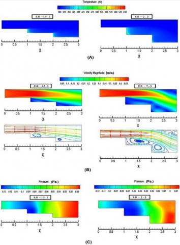
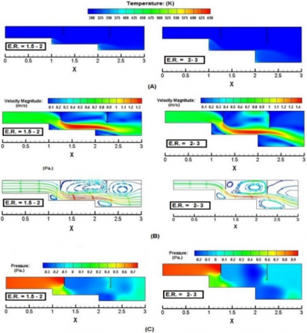
The numerical results in Figure 2(A) are obtained in a duct configuration without a baffle. The surface temperatures at the corner of the SE duct are high because of air secondary recirculation, which has low velocity at the corner of the SE zone. The air temperature decreases as the step height increases because the air flow becomes steady and uniform. Increasing the ER may extend the recirculation region, resulting in less heat transfer between the heated surface and air. As shown in the figure, at ER = 2-3, when the step height increases, the variation in fluid temperature extends along the step length owing to large recirculation and separation that reduce the local heat transfer intensity.
Figure 2. Channel without baffle for different expansion ratios: (A)Thermal field contour, (B) velocity contour, and (C) pressure contour
Figure 2(B) illustrates the velocity distribution at different ERs. At ER = 1.5-2, the recirculation zone in the first step has a height approximately equal to the step height, and its length is 40% of the step length; meanwhile, the recirculation zone in the second step is smaller than that in the first step with a height about 80% of the step height, and its length is approximately 20% of the step length. When ER = 2-3, the intensity of the vortices is greater than that at ER = 1.5-2, the recirculation zone height in the first step is equal to the step height, and its length extends to about 95% of the step length. In the second step, the recirculation height exceeds the step height, and the recirculation region length is about 70% of the step length.
The pressure drop along the duct is demonstrated in Figure 2(C). As the cross-sectional area abruptly changes at the SE, pressure loss in the downstream duct is noticed. At a constant Reynolds number, the pressure loss increases as the ER increases because of the enlarged recirculation region. The pressure drop in the first step is higher than that in the second step, and the length over which pressure recovery occurs increases with higher ERs.
3.2 Effect of baffle angle
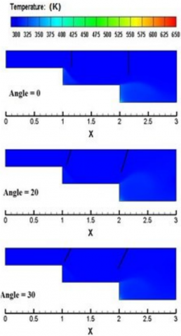
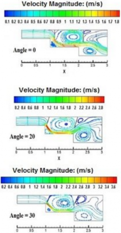
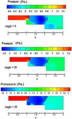
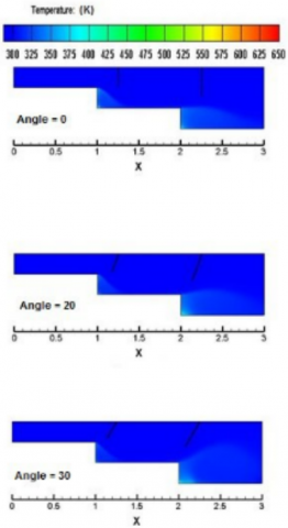
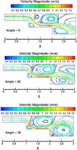
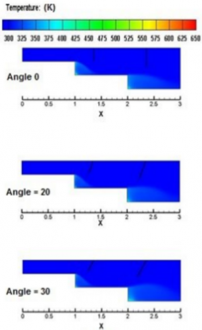
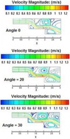
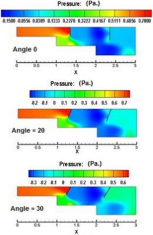
Figure 3 shows the temperature distribution, pressure drop, and velocity distribution at ER = 2-3 and baffle location 15 cm from steps (S = 15 cm) with varying baffle tilt angle (θ = 0°, 20°, 30°). The temperature distribution at a baffle angle of 0° demonstrates that the first and second baffles steer air directly towards the heated surface, which leads to increased heat transfer and air temperature gradient more than those in the case without baffles. When the baffle angle becomes 20° and 30°, the distance between the heated surface and baffles creates a jet which increases the air velocity, consequently improving heat transfer due to the increasing size of the vortex structures.
The velocity distribution at θ = 0° indicates an apparent separation zone and a large vortex behind the baffle with a high velocity zone of 1.8 m/s concentrated at the edge of the baffle close to the heated surface in the first step. The secondary recirculation zone is small compared with that formed in the second step. At θ = 20°, 30°, the velocity distribution is similar to that at θ = 0°, with the secondary recirculation zone appearing at the corner of the first step and behind the base of the second baffle. The maximum velocities at θ = 20°, 30° are 2.8 and 3.6 m/s, respectively, which can be attributed to the jet effect mentioned before. The pressure contours at θ = 0°, 20°, and 30° illustrate an increase in pressure drop at θ = 30° of about 360% compared with that at θ = 0° due to the high throttling effect resulting from the baffle orientation.
Figure 3. Channel with baffle at different angles, (ER = 2-3) and (S = 15 cm): (A) Thermal field contour, (B) velocity contour, and (C) pressure contour
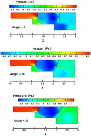
Figure 4 illustrates the temperature distribution, pressure drop, and velocity distribution at ER = 2-3 and baffle location 25 cm from steps (S = 25 cm) with variations in baffle tilt angle (θ = 0°, 20°, 30°). The temperature distribution is similar to that at S = 15 cm, except in the second step region, where the air temperature increases because the baffles steer air directly into the heated surface with increasing air mixing and turbulence. The pressure drop at S = 25 cm is less than at S = 15 cm because the baffle–step distance increases, which consequently minimizes the sudden contraction. By contrast, the baffles and steps form a sudden contraction at S = 15 cm that leads to high pressure losses as air flows through the duct. The velocity distribution indicates some difference as S changes from 15 cm to 25 cm in the second step, in which the recirculation zone expands and occupies the entire region. This phenomenon affects the convective heat transfer.
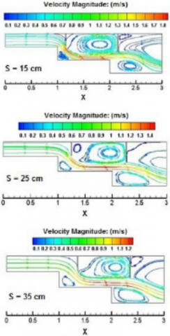
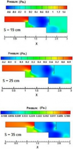
The temperature distribution, velocity distribution, and pressure drop when S = 35 cm are demonstrated in Figure 5. The effect of increasing S is evident in the second step, demonstrating enhanced heat transfer and decreased temperature at the corner that prevents thermal stress in this region. Moreover, the recirculation intensity is increased, whilst the pressure drop is decreased.
Figure 4. Channel with baffle at different angles, (ER = 2-3) and (S = 25 cm). (A) Thermal field contour, (B) velocity contour, and (C) pressure contour
Figure 5. Channel with baffle at different angles, (ER = 2-3) and (S = 35 cm): (A) Thermal field contour, (B) velocity contour, and (C) pressure contour
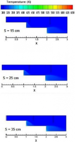
Figure 6. Channel with baffle at different spacing, (ER = 2-3) and (θ = 0): (A) Thermal field contour, (B) velocity contour, and (C) pressure contour
3.3 Effect of baffle spacing (S)
Figure 6 depicts the temperature gradient, pressure drop, and streamlines of velocity for various baffle locations from steps (S = 15, 25, 35 cm) at a tilt angle of 0°. The temperature distribution of air demonstrates that the best distance is 15 cm, which leads to increasing air temperature whilst decreasing the temperatures at both corners and along both steps of the SE duct. The heat transfer level is rather dominated by vortex configurations. Velocity streamlines indicate that as the distance increases, the intensity of the recirculation region downstream of the baffles decreases, and a secondary recirculation zone appears.
Figure 7. Channel with baffle at different Expansion ratios, (S = 25) and (θ = 0): (A) Thermal field contour, (B) velocity contour, and (C) pressure contour
3.4 Effect of expansion ratio (with baffle)
Figure 7 shows the performance of the air flow of the double-stepped SE duct for baffle angle θ = 0° and S = 25 cm for two ERs = 1.5-2, 2-3. The temperature distributions for both ER have similar patterns, whilst the heat transfer and temperature gradients at both step corners are greater at ER = 1.5-2. The pressure drop is higher at ER = 2-3 because of the considerable change in the cross-sectional area. A negative-pressure region at recirculation zones is identified downstream of the baffles and at the second corner. The velocity distribution at ER = 1.5-2 illustrates that the recirculation zone occupies the whole area between the two baffles; at ER = 2-3, the vortex becomes smaller, and a secondary recirculation zone appears behind the first baffle.
3.5 Heat transfer results
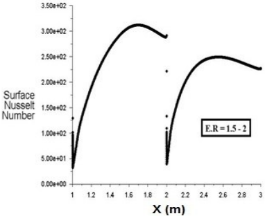
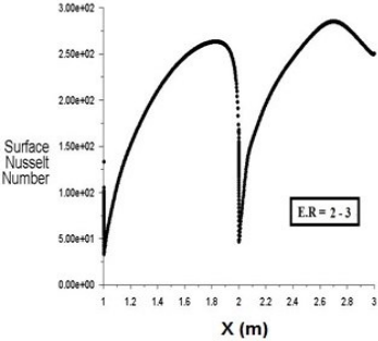
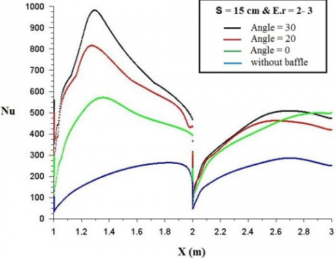
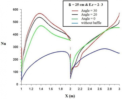
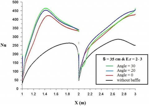
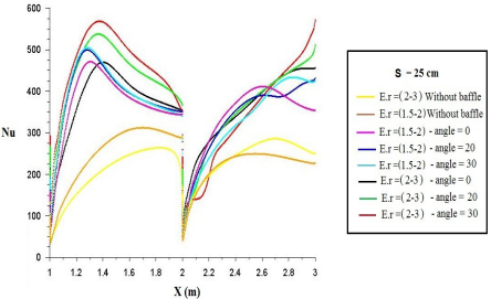
The local Nusselt number variation along the lower heated wall of the double-stepped SE is demonstrated in Figure 8. For both SE configurations, the maximum local Nusselt number occurs after the recirculation zone at the attachment point owing to the minimized effect of the boundary layer. As the ER increases, the position of maximum Nu shifts downstream from the sudden step location. Beyond this point, the Nusselt number gradually decreases in the downstream direction due to the development of the thermal boundary layer near the wall. At the second expansion step, the Nusselt number reaches a minimum, primarily due to the strong expansion, which leads to increased local temperatures. As the ER increases, the location of the peak Nusselt number shifts further downstream from the step. This can be attributed to the vortex effect. For ER = 1.5-2, the peak Nu positions are approximately 0.7 m and 1.45 m from the first step, while for ER = 2-3, they occur at around 0.82 m and 1.7 m. Local Nusselt number variations downstream of expansion steps for ER = 2-3 and diverse baffle angles (0°, 20°, and 30°) and baffle distances from steps (15, 25, and 35 cm) are shown in Figure 9. For all the different parameters discussed, local Nusselt number curves follow the same trends. The baffled SE duct exhibits an augmented heat transfer compared with the duct without baffles. The highest Nu value is determined at a position closer to the expansion steps, as the recirculation zone is destroyed by the main flow, which is directed by baffles into the heated surface. The optimum heat transfer is observed at the configuration of θ = 30°, S = 15 cm, and ER = 2-3 because this configuration allows larger and more intense recirculation zones. At X ≈ 1.3 m, the Nusselt number for θ = 30° and S = 15 cm is increased by about 71.9% and 19.5% compared with those at θ = 0°, 20°, respectively. This enhancement is attributed to the strong mixing between the hot air close to the wall and the colder flow, which is directed by the baffles and generates strong vortices. Figure 10 compares the Nusselt number for all configurations at a baffle position of S = 25 cm. At X ≈ 1.3 m and θ = 30°, the case with ER = 2–3 shows an ~14% improvement in Nu compared with that at the same θ with ER = 1.5-2 and an ~22.5% improvement compared with that at the same ER with θ = 0°.
(B)
Figure 8. Local Nusselt number along the lower heated wall at different expansion ratios (without baffle)
Figure 9. Local Nusselt number along the lower heated wall at different baffle positions for ER = 2–3: (A) S = 15 cm, (B) S = 25 cm, and (C) S = 35 cm
Figure 10. Local Nusselt number along the lower heated wall at (S = 25 cm) for different expansion ratios and baffle angles
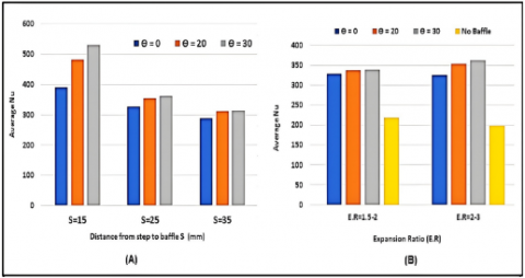
Figure 11 demonstrates a comparison of average Nusselt numbers for all configurations. The influence of baffle location at different baffle angles is highlighted in Figure 11(A). The comparison shows that the air jet has a slight effect on average Nu for cases with a baffle distance of more than 15 cm because of the increased cross-sectional area between corners and baffle edges. Moreover, the average Nu is rather unaffected by an increase in baffle angle to more than 20° for the same previous reason. By contrast, the baffle angle considerably influences the average Nu at S = 15 mm because of the jet effect of air flow. Figure 11(B) shows the effect of ER for the cases without and with a baffle at different angles. The average Nu is greatly improved with the addition of baffles owing to vortex formation, whilst it is slightly affected by the increase in angle because of the enlarged distance between step corners and baffle edges. Furthermore, the figure demonstrates increased average Nu with increasing ER. This result can be attributed to the larger size and intensity of vortices shown in Figure 7, as previously explained in the related section.
Figure 11. Comparison of average Nusselt number (Nu): (A) at ER = 2-3 with different baffle spacing, and (B) at S = 25 mm with different expansion ratios
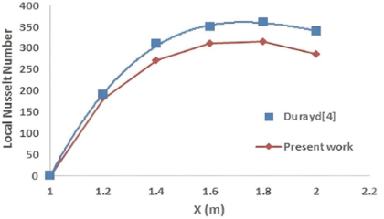
The simulated model is validated through comparison with a previous work [8], which was conducted under approximating conditions. The basic parameter used for comparison is the local Nusselt number along the duct length (X). Figure 12 compares the results from the present study and the previous work for ER = 2 without baffles. This comparison indicates good agreement with an error range between 5.8% and 12.3%. The variance between the results can be ascribed to the test conditions that affect the flow performance, such as air flow rate and applied heat flux. The increase in the difference between the symmetrical results with increasing distance X is attributed to the cumulative effect of the dissimilarity of some operating conditions.
Figure 12. Comparison of present results with previous work at ER = 2 without baffles
The numerical simulation in this work was conducted by utilizing ANSYS Fluent to investigate the heat transfer of air flow through a double-stepped SE duct incorporating two baffles on the top surface. The numerical simulation was performed under different angles, positions, and lengths of thin baffles employed to generate vortices and enhance the convective heat transfer. The simulation results were compared with those from a previous work to ensure validation. The following conclusions were drawn:
1. The addition of baffles decreases the temperature gradient along the duct, where the corner temperature decreases by about 20℃.
2. Increasing the ER leads to enhanced heat transfer for all the considered configurations, which consequently increases the fluid temperature in the SE duct because of larger and more intense vortices.
3. Increasing the baffle angle to 30° creates a region between baffles and corners as a jet that increases the air velocity and enhances the heat transfer.
4. The temperature distribution of air demonstrates that the best distance (S) is 15 cm. This finding is explained through the velocity streamline, in which setting S = 15 cm increases the size and intensity of vortices. On the contrary, these vortices are larger but with less intensity when S = 25 cm.
5. The comparisons between the present simulation and previous work results reveal good agreement with an error range between 5.8% and 12.3% for the case without a baffle due to test conditions.
6. Analysis of double-stepped SE ducts with holed baffles for heat transfer enhancement is recommended.
The authors extend their appreciation to the Middle Technical University- Iraq for its support of this paper.
[1] Ramanathan, S., Parabhu, S., Mohankumar, R.S., Suresh, T. (2019). Research on effects of obstacles on heat transfer and fluid flow in backward facing step flow. International Journal of Innovative Technology and Exploring Engineering (IJITEE), 8(9S2): 417-421. http://doi.org/10.35940/ijitee.I1089.0789S219
[2] Jehhef, K.A., Abid Aun, S.H., Siba, M.A. (2020). Theoretical study of the film boiling heat transfer of different nanofluids on the vertical heated surface. IOP Conference Series: Materials Science and Engineering, 745(1): 012061. https://doi.org/10.1088/1757-899X/745/1/012061
[3] Maid, I.W., Hilal, K.H., Lafta, N.S. (2020). Numerical analysis for enhancing transferred heat in porous counter flow heat exchanger. IOP Conference Series: Materials Science and Engineering, 745(1): 012081. https://doi.org/10.1088/1757899X/745/1/012081
[4] Salah, H., Muthana, L., Al-Zuhairy, R. (2020). The influence of ambient conditions on compression ignition engine performance: Experimental study. Journal of Mechanical Engineering Research and Developments, 43(7): 317-325. https://www.researchgate.net/publication/396585549.
[5] Ota, T. (2000). A survey of heat transfer in separated and reattached flows. Applied Mechanics Reviews, 53(8): 219-235. https://doi.org/10.1115/1.3097351
[6] Chen, L., Asai, K., Nonomura, T., Xi, G., Liu, T. (2018). A review of Backward-Facing Step (BFS) flow mechanisms, heat transfer and control. Thermal Science and Engineering Progress, 6: 194-216. https://doi.org/10.1016/j.tsep.2018.04.004
[7] Salman, S., Abu Talib, A.R., Saadon, S., Hameed Sultan, M.T. (2020). Hybrid nanofluid flow and heat transfer over backward and forward steps: A review. Powder Technology, 363(1): 448-472. https://doi.org/10.1016/j.powtec.2019.12.038
[8] Mahmood, D., Hilal, K., Abid Aun, S. (2024). Numerical investigation of heat transfer characteristics and flow structure inside sudden expansion channel. AIP Conference Proceedings, 3002(1): 080006. https://doi.org/10.1063/5.0206525
[9] Dağtekin, İ., Ünsal, M. (2011). Numerical analysis of axisymmetric and planar sudden expansion flows for laminar regime. International Journal for Numerical Methods in Fluids, 65(9): 1133-1144. https://doi.org/10.1002/fld.2239
[10] Roy, V., Majumder, S., Sanyal, D. (2010). Analysis of the turbulent fluid flow in an axi-symmetric sudden expansion. International Journal of Engineering Science and Technology, 2(6): 1569-1574. https://api.semanticscholar.org/CorpusID:17962518.
[11] Lee, D.H., Lee, J.S., Park, H.J., Kim, M.K. (2011). Experimental and numerical study of heat transfer downstream of an axisymmetric abrupt expansion and in a cavity of a circular tube. Journal of Mechanical Science and Technology, 25(2): 395-401. https://doi.org/10.1007/s12206-010-1222-6
[12] Wong, M.K., Sheng, L.C., Azwadi, C.N., Hashim, G.A. (2015). Numerical study of turbulent flow in pipe with sudden expansion. Journal of Advanced Research in Fluid Mechanics and Thermal Sciences, 6(1): 34-48. https://semarakilmu.com.my/journals/index.php/fluid_mechanics_thermal_sciences/article/view/2538.
[13] Hajji, H., Kolsi, L., Ghachem, K., Maatki, C., Hussein, A., Borjini, M. (2021). Numerical study of heat transfer and flow structure over a microscale back step. Alexandria Engineering Journal, 60(3): 2759-2768. https://doi.org/10.1016/j.aej.2021.01.016
[14] Ghadhban, S.A., Salah, H., Jehhef, K.A. (2020). Numerical modelling of fluid flow and heat transfer of (TiO₂–water) nanofluids in wavy duct. IOP Conference Series: Materials Science and Engineering, 881(1): 012162. https://doi.org/10.1088/1757-899X/881/1/012162
[15] Aun, S.H.A., Ghadhban, S.A., Jehhef, K.A. (2021). Experimental and numerical investigation of convection heat transfer in an enclosure with a vertical heated block and baffles. Journal of Thermal Engineering, 7(3): 367-386. https://doi.org/10.18186/thermal.878156
[16] Mushatet, K.S. (2011). Simulation of turbulent flow and heat transfer over a backward facing step with ribs turbulators. Thermal Science, 15(1): 245-255. https://doi.org/10.2298/TSCI090926044M
[17] Heshmati, A., Mohammed, H., Parsazadeh, M., Fathinia, F., Wahid, M., Sies, M., Saat, A. (2013). Effect of vertical baffle installation on forced convective heat transfer in channel having a backward-facing step. Applied Mechanics and Materials, 388: 169-175. https://doi.org/10.4028/www.scientific.net/AMM.388.169
[18] Boruah, M., Randive, P., Pati, S. (2018). Hydrothermal performance and entropy generation analysis for mixed convective flows over a backward facing step channel with baffle. International Journal of Heat and Mass Transfer, 125: 525-542. https://doi.org/10.1016/j.ijheatmasstransfer.2018.04.094
[19] Kumar, S., Vengadesan, S. (2019). The effect of fin oscillation in heat transfer enhancement in separated flow over a backward facing step. International Journal of Heat and Mass Transfer, 128: 954-963. https://doi.org/10.1016/j.ijheatmasstransfer.2018.09.001
[20] Saha, S., Biswas, P., Jha, K., Das, A., Choudhary, R. (2023). Newtonian hydro-thermal fluid flow phenomena through a sudden expansion channel with or without baffles. Kuwait Journal of Science, 50(3B): 1-20. https://doi.org/10.48129/kjs.18147
[21] Alqahtani, S., Alshehery, S., Bayram, M., Ikumapayi, O.M., Akinlabi, E.T., Akinlabi, S.A., Menni, Y. (2023). Enhancing flow structure in heat exchangers analysis of dynamic and thermal air-flow behavior with perforated and inclined baffles. Thermal Science, 27(4 Part B): 3269-3280. https://doi.org/10.2298/TSCI2304269A
[22] Wang, S., Burton, D., Sheridan, J., Thompson, M. (2014). Characteristics of flow over a double backward-facing step. In 19th Australasian Fluid Mechanics Conference, Melbourne, Australia, pp. 8-11.
[23] Rehman, K.U., Shatanawi, W., Çolak, A.B. (2022). Thermal analysis of flowing stream in partially heated double forward-facing step by using artificial neural network. Case Studies in Thermal Engineering, 37: 102221. https://doi.org/10.1016/j.csite.2022.102221
[24] Oztop, H.F., Mushatet, K.S., Yılmaz, İ. (2012). Analysis of turbulent flow and heat transfer over a double forward facing step with obstacles. International Communications in Heat and Mass Transfer, 39(9): 1395-1403. https://doi.org/10.1016/j.icheatmasstransfer.2012.07.011
[25] Togun, H., Shkarah, A.J., Kazi, S.N., Badarudin, A. (2013). CFD Simulation of heat transfer and turbulent fluid flow over a double forward-facing step. Mathematical Problems in Engineering, 2013(1): 895374. https://doi.org/10.1155/2013/895374
[26] Abdulrazzaq, T., Togun, H., Alsulami, H., Goodarzi, M., Safaei, M.R. (2020). Heat transfer improvement in a double backward-facing expanding channel using different working fluids. Symmetry, 12(7): 1088. https://doi.org/10.3390/sym12071088
[27] Mohankumar, V., Prakash, K.A. (2024). Numerical investigation of fluid flow and heat transfer characteristics over double backward-facing step with obstacles. Heat Transfer Engineering, 45(9): 779-799. https://doi.org/10.1080/01457632.2023.2220474
[28] McQueen, T., Burton, D., Sheridan, J., Thompson, M.C. (2022). The double backward-facing step: Effect of forcing on interacting separated flow regions. Journal of Fluid Mechanics, 946: A9. https://doi.org/10.1017/jfm.2022.543
[29] Bahrami, H.R., Ghaedi, M. (2024). Enhancement of thermal energy transfer behind a double consecutive expansion utilizing a variable magnetic field. Scientific Reports, 14(1): 10236. https://doi.org/10.1038/s41598-024-60953-3
[30] Kanna, P.R., Sivakumar, Y., Prasad, G.D., Taler, D., Sobota, T., Taler, J. (2025). Numerical investigation of flow and heat transfer from twin circular cylinders present in double forward-facing step. Fluids, 10(2): 48. https://doi.org/10.3390/fluids10020048
[31] Jahin, A.S., Samin, J.H., Chhoa, M.F., Faisal, F., Nokib, M.H.I., Rabby, M.I.I. (2025). Computational study of thermofluidic characteristics of Al2O3-Cu hybrid nanofluids in backward facing step channel with varying step angles. Heliyon, 11(4): e42638. https://doi.org/10.1016/j.heliyon.2025.e42638
[32] Alsabery, A.I., Abosinnee, A.S., Ismael, M.A., Ali, I.R., Hashim, I. (2025). Forced convection flow of nanofluid within partially filled porous backward-facing step wavy channel. Thermal Science and Engineering Progress, 60: 103422. https://doi.org/10.1016/j.tsep.2025.103422
[33] Yilmaz, I., Oztop, H.F. (2006). Turbulence forced convection heat transfer over double forward facing step flow. International Communications in Heat and Mass Transfer, 33(4): 508-517. https://doi.org/10.1016/j.icheatmasstransfer.2005.08.015
[34] Launder, B.E., Spalding, D.B. (1974). The numerical computation of turbulent flows. Computer Methods in Applied Mechanics and Engineering, 3(2): 269-289. https://doi.org/10.1016/0045-7825(74)90029-2
[35] ANSYS, Inc. (2016). ANSYS fluent user’s guide (Release 17.2).