Ismail Ibrahim Marhoon*![]() | Ahmed Hashim Kareem
| Ahmed Hashim Kareem![]() | Samir Ali Amin
| Samir Ali Amin![]() | Ouf A. Shams
| Ouf A. Shams![]() | Hasan Shakir Majdi
| Hasan Shakir Majdi![]()
© 2025 The authors. This article is published by IIETA and is licensed under the CC BY 4.0 license (http://creativecommons.org/licenses/by/4.0/).
OPEN ACCESS
This research evaluates preheating effects on the microstructure and strength aspects in gray cast iron shielded metal arc welded using ENi-CI electrodes. The research evaluated the joint integrity without and 150℃ and 300℃ preheat temperatures. Preheating treatment has profound effect on graphite retention amount, produces both carbides, and alters the stress field in welding joint. When there is no preheating the weld zone develops a damaged graphite structures and excessive martensitic structures together with high carbide formation which produces brittle zones prone to cracking. Hardness in the heat-affected zone reached unacceptable levels exceeding 50 HRC together with inadequate mechanical properties. 150℃ temperature preheating resulted in limited graphite preservation resulting in decreased carbide content and decreased martensite formation which produced a hardness area between 48.5-49 HRC throughout HAZ. 300℃ preheating temperature delivered well-refined microstructure along with complete graphite preservation and minimal carbide formation and ferritic-pearlitic matrix that together produced the lowest HAZ hardness variations that approached 48 HRC. Embrittling precipitation phases within the fusion line and HAZ regions decreased from 50.5 HRC to 49.5 HRC following preheating at 150℃ and to 49.3 HRC at 300℃. Both tensile tests demonstrated that weld samples preheated to 300℃ demonstrated better mechanical stability because they showed ductile structural failure but initial samples without preheating displayed brittle fractures due to high residual stresses. The analysis validates that welding cast iron at 300℃ preheating results in the best results since this temperature regulates thermal gradients and maintains graphite stability while stopping brittle martensitic phases formation to achieve improved weld quality.
preheating optimization, gray cast iron, microstructural evolution, crack prevention, thermal gradient control
Welding of cast iron, particularly attractive due to its ability to create complex shapes and good fatigue limit, has been researched in order to optimize the method for increasing weldability and the mechanical characteristics of the welded joint. Thus, this review concentrates on the effects of pre-heating and the assessment of fusion welding without pre-heating, welding pre-heating has been found to extend the life of the welds by minimizing thermal stresses and cracking liability. For instance, other past papers such as Kumar et al. [1] established that pre-heating assist in the enhancement of microstructure and hardness of grey cast iron, so as to check sharp rates of cooling. In the same way, Dametew [2] considered the use of pre-heating for the process of decreasing the thermal gradients and increasing the rate of fusion and decreasing the number of defects on metal products. These studies always emphasize that pre heathers set a restricted thermal condition hence reducing the brittle fracture dangers that result from fusion welding. Conversely, failure to preheat can cause severe mechanical property loss, as elaborated by Gouveia et al. [3]. Inadequate preheat is associated with development of hard fusion zones, higher residual stress, and possibility of weld metal cracking. White [4] also indicated that cast iron welding processed without preheating entail high cooling rates that are unfavorable to the tough weldment joints. Some new developments that have been deemed helpful in solving some of these challenges include laser based preheating, post heating. Saffer et al. [5] proved that the described methods allow maintaining the necessary thermal gradients and increasing weld joint reliability. Furthermore, Yuan et al. [6] offered a comprehensive discussion of the influence of pre-heating on residual stress and deformation as well as profiles of butt-welded casts iron confirming the importance of thermal control in cast iron welding. Pre-heating which is among the most important preparation methods assures proper distribution of heat to the base material and to overcome brittleness in cast iron welds. For instance, Gouveia et al. [7] underwent experiments with high strength ductile cast iron and discovered that the 3 cycles of preheating of 300℃ helped improve tensile functions and reduce thermal crack. Srivastava et al. [8] affirmed these outcomes by revealing that pre-heating can reduce thermal gradients and increase weld ductility. Moreover, Akinribide et al. [9] examined heat treatment practice for cast iron and found out higher mechanical properties of cast iron samples when have been preheated at 450℃. Casting process was systematized, which led to the decrease of carbide formation at the line of fusion, which is a guideline in enhancing the joint strength. The main problems that can be encountered when welding without pre-heating is that the residual stress sense and the microstructure can be quite heterogeneous. Direct welding as noted by Bhatnagar and Gupta [10] organize a sharp arc owned to rapid cooling, engulfs brittle fracture zone and in order to regain mechanical strength post weld heat treatment is required. Likewise, Rada [11] observed that in the absence of pre-heating, there were steep variations of the temperature field in the welded joints as well as the accumulated residual stress and deformation. Laser-assisted pre-heating is another form that has brought modernity in order to address these difficulties. Liu et al. [12] found out that low laser power controlled portion can significantly reduce the fusion zone defects and enhance the joint’s toughness. This method is progress from the previous methods, and it affords good control over thermal inputs. In fusion welding, pre-heating is important to minimize the thermal stress, and optimize the mechanical characteristics of the joint. Gucwa et al. [13] explored the effects of pre-heating in welding wear-resistance high chromium cast iron primarily: increased material thickness toughness and reduced micro crack formation. The use of induction based pre-heating as outlined by Dhara and Biswas [14] also revealed enhanced joint quality and mechanical properties in the enhanced alloys. Similarly, Charkhi and Akbari [15] investigated the repair welding processes with conclusion that pre-heating could successfully minimize the residual stress problems that are well known in fusion welding. These studies highlight the value of pre-heating in order to prevent cracking of welded joints under thermal stresses. In the same regard, Chamim et al. [16] pointed out that pre-heating notwithstanding, filler-metal and post-weld thermal-treatment turn into important considerations. These approaches tend to tackle weld defects that result from an aggressive cooling rate during the weld procedure.
Research studies preheating methods effects on gray cast iron weldments by evaluating how these methods influence graphite features stability and the carbides development. The research on welding demonstrates preheating represents vital process requirement because it reduces thermal stress and leads to better welding junction quality and lessens cracking problems. Research investigates experimental procedures using the setup design complete examinations together with experimental outcomes and their analytical assessment. Experimental Procedure section lists materials like gray cast iron and ENi-CI welding electrodes alongside welding process descriptions conducted at no preheating, 150℃ and 300℃ preheating temperatures. Results and discussion section shows how preheating temperatures influence the microstructure features including graphite maintenance and carbide evolution and the HAZ hardness results. Final results in conclusions section show that using 300℃ preheating enhances weld integrity through its ability to decrease brittleness while reducing carbide development and maintaining graphite structures.
2.1 Investigation materials
For the base material, gray cast iron FC 300 JIS G5501 is chosen in this study. The chemicals in the water sample are described in Table 1. Three types of fusing were done, using an electrode ENi-Cl (AWS A5.15, 3.2 mm). The first was done without preheating, the second at 150℃ preheat and the third at 300℃ preheat. The makeup of welding electrodes is listed in Table 2. Welding used a single V-shape, whose angle was 60° as it was described in the standard AWS A2. When welding begins, each end is shielded to avoid the specimen changing shape because of the heat and during welding it is treated as a massive or solid material.
Table 1. FC 200 gray cast iron chemical composition (% by weight)
|
Elemant |
Wt%. |
|
C |
3.2 |
|
Si |
1.79 |
|
Mn |
0.46 |
|
S |
0.12 |
|
P |
0.2 |
|
Ni |
0.06 |
|
Cr |
0.12 |
|
Cu |
0.08 |
Table 2. ENi-Cl nickel base electrode chemical composition (% by weight)
|
Elemant |
Wt%. |
|
C |
1.1 |
|
Si |
0.32 |
|
Mn |
0.01 |
|
S |
0.001 |
|
P |
0.01 |
|
Ni |
Bal. |
2.2 Preheating temperature and welding method selection
Preheating temperature selection determines how welding-generated thermal gradients will progress. Previous study along with practical welding standards determined these three no preheating and 150℃ and 300℃ preheating temperatures. Experimental temperatures arranged to research thermal assistance effects that transitioned from baseline conditions up to moderate and high preheating conditions. Authors picked ENi-CI welding electrodes due to it excellence in joining cast iron materials. Experimental welding procedures exclusively used manual metal arc welding as their technique. All welding parameters maintained 120 A current while using 24 V voltage and 2 mm/s welding speed during all experimental phases. Experiments employed constant values set. The experimental results needed reliable replication thus laboratory investigations took place under controlled humidity and ambient temperature conditions. An identical gray cast iron batch served to prepare all specimens in order to maintain consistent material properties. systematic approach monitored space, heat-affected zones (HAZ) width, and cooling speeds for welds throughout all examinations. A precise experimental setup effort focused on fixture alignment together with high cleaning level was performed for every sample.
2.3 Instruments
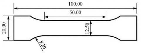
To analyze the joints' microscopic surface features, a Zeiss Imager M2m optical microscope was used and the finer features were studied using a FEI Quanta 250 SEM. A SEM was linked to an energy dispersive spectroscopy (EDS) to look into the chemical composition of the weld zones. A cross-section from the welding joint was hardness-tested with a Vickers Hardness Machine HVD-1500AT under ASTM E384-11e1 rules. Testing for tensile mechanical properties of welded joints followed ASTM E8/E8m-15a using a servo hydraulic universal system with a load cell of 600 kN to 1500 kN. Figure 1 shows the dimensions for the tensile test samples used in the experiment.
Figure 1. Tensile test specimen dimension
2.4 Measuring procedure
Samples of the welding joints cross-sections were mechanically prepared for metallography by removal of the surface layer, followed by polishing and etching. 5 grams FeCl3, 10 ml HCl, and 150 ml distilled water used for chemical etching reagents. Rockwell hardness test was done at 1 mm intervals across welding joint. Test was done vertically through the weld zones and across the welds to generate hardness map. Joints tensile properties determined by measuring tensile under load using Servo Hydraulic Universal Testing System According to ASTM E8/E8m-15a.
3.1 Base metal microstructure analysis
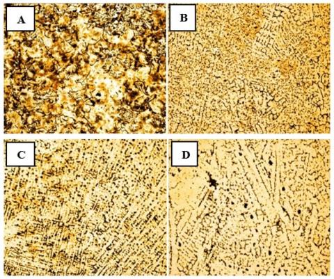
The optical micrograph microstructure test picture in Figure 2(A) shows the initial microstructure of gray cast iron in as received conditions before metallurgical modification. The microstructure illustrated graphite flakes in a ferrite-pearlite matrix, the graphite flakes disperse throughout the matrix space with a dark and irregular shape. Due to their two-dimensional nature the metallographic samples display graphite flakes that adopt various orientations. Lighter and intermediate colors in the image represent the ferrite-pearlite matrix while the background structure consists of both phases. The graphite flakes show random interconnected elongated appearance that characterizes gray cast iron. Varied dimensions of graphite flakes in the material determine its mechanical properties. The mechanical strength suffers as well as the material toughness diminishes when graphite flakes grow in size but smaller flakes enhance wear resilience. The graphite flakes in the image have dark surrounding areas representing pearlite made from α ferrite and cementite (Fe3C) layers. The arrangement of material components makes possible both high wear resistance and increased hardness for gray cast iron [17]. The image shows the presence of ferrite as light areas in its structures. Slow cooling of the material promotes carbon diffusion from austenite due to its presence of ferrite. The analyzed regions also show distinct phase patterns that may be eutectic cementite or carbide networks based on the elements present in the cast iron.
Figure 2. FC 200 gray cast iron as received base metal and weld metal microstructures: (A) gray cast iron base metal, (B) weld metal without preheating, (C) weld metal with 150℃ preheating, and (D) weld metal with 300℃ preheating
The mechanical strength suffers as well as the material toughness diminishes when graphite flakes grow in size but smaller flakes enhance wear resilience. The graphite flakes in the image have dark surrounding areas representing pearlite made from α ferrite and cementite (Fe3C) layers. The arrangement of material components makes possible both high wear resistance and increased hardness for gray cast iron. The image shows the presence of ferrite as light areas in its structures [18]. Slow cooling of the material promotes carbon diffusion from austenite due to its presence of ferrite. The analyzed regions also show distinct phase patterns that may be eutectic cementite or carbide networks based on the elements present in the cast iron [19].
3.2 Welding zone microstructure analysis
When weld pools rapidly cool down after welding cast iron often create unwanted hard metal phases such as martensite along with carbides inside the fusion zone together with the HAZ [20]. The different phases that develop after welding cause increased material brittleness resulting in structure failure through the formation of cracks. The preheating process helps decrease cooling speed which gives adequate carbon diffusion time along with sufficient graphite retention to prevent brittle microstructure development. Research explores the structural changes which occur within shielded metal arc welded (SMAW) gray cast iron weld zones following different preheating protocols [21]. Nickel-based ENi-CI electrode stands out because it makes both graphite development and ductility improvement possible.
3.2.1 Without preheating welding zone microstructure analysis
The microstructure originates from gray cast iron welded through SMAW with ENi-CI electrodes under unspecified preheating conditions weld zone illustrated in Figure 2(B). The evaluation reveals the details of solidification processes alongside phase segmentation along with possible welding defect formations [22]. Figure 2(B) display nickel abundance with an austenitic structure that exhibits dendritic and cellular microstructural patterns. The weld metal obtains enhanced ductility as well as crack resistance from nickel-stabilized austenitic phase formation supported by ENi-CI electrode nickel content. The black irregular networks along with isolated areas in the image represent graphite flakes and carbon segregation areas. Partial graphite dissolution happens in areas of rapid solidification because the metal did not receive preheating treatment but other areas transformed carbon into carbide networks and interdimeric graphite. The localized carbon migration occurs because of the intense thermal gradient within the weld metal. Areas with various carbide distributions resembling Fe3C (iron carbide or cementite) present combined high hardness and inferior toughness. The rapid cooling rate without preheating creates conditions that stop carbon diffusion into graphite until it results in carbide formation. The presence of nickel in steel stabilizes austenite until some zones maintain this phase (γ-phase). Nevertheless, thermal stresses induced by rapid cooling can transform austenite into martensite at grain boundaries. The transformation process causes material brittleness and enhances the likelihood of HAZ cracking [23]. The observed microstructure depends on the welding thermal cycle along with the lack of preheating due to its effects on carbon displacement mechanisms as well as cooling rates and solid-state phase changes. ENi-CI electrode containing nickel operates as a graphitization promoter during gray cast iron welding because it stabilizes austenite and blocks carbide development [24]. The welding process develops graphite reprecipitation at grain boundaries along with carbide network formation when preheating is omitted. The carbon atoms stay trapped as they cannot pass through to the austenite matrix that leads to their formation into brittle Fe3C carbides. The process of graphite flakes dissolving releases excess carbon that may act as another factor in the development of carbides in the material [25]. High levels of nickel within the electrode prevent pearlite and ferrite from forming so the weld metal obtains a stable austenitic microstructure. Part of the remaining austenite can transform into martensite during cooldown that raises the potential for microcrack formation and material fragility [26].
3.2.2. 150℃ preheating welding zone microstructure analysis
The optical microscope image in Figure 2(C) demonstrates the gray cast iron Shielded Metal Arc Welding joint area microstructure produced using an ENi-CI electrode under preheating conditions at 150℃. The micrograph shows the graphite flakes existing as dark regions that define gray cast iron material. The characteristics of graphite flake distribution and dimension depend on both manufacturing patterns of the original casting material and the heating process from welding. Heat generated from welding could cause minor graphite flake dissipation and displacements. Ferrite predominates as the light-colored material throughout the metal structure yet the brownish areas demonstrate pearlite presence [27]. The nickel-based ENi-CI electrode enables the formation of a microstructure with a soft matrix where ferrite and pearlite are present because it maintains graphite retention while reducing carbide development. Nickel acts as an austenite stabilizer to prevent carbide development and protect graphite flakes from breaking which decreases the chance of brittle white iron appearance. Areas containing nickel-rich phase could control stabilizing austenite or create retained austenite when cooling occurred slowly because of preheating conditions [28]. Nickel absorption by the cast iron during welding operation leads to phase composition changes thus producing a weld zone with improved ductility. 150℃ preheating helps decrease thermal shock effects which lowers the formation of martensite and carbides in the HAZ.
The cooling speed becomes slower as preheating temperatures rise that allows graphite to maintain stability while stopping brittle hard carbide networks from forming. Welding at a temperature of 150℃ before application creates an even heat distribution through minimizing the temperature difference between arc and base material. The reduced cooling speed triggers the retention of graphite flakes instead of producing hard martensite structures. The controlled cooling rate protected graphite flakes while maintaining their stability thus blocking the formation of hard carbide ledeburite microstructures. Some nickel-rich austenite together with retained austenite remains present in the microstructure because nickel functions as an austenite-stabilizing element.
3.2.3 300℃ preheating welding zone microstructure analysis
The optical image in Figure 2(D) displays a characteristic microstructure of welded gray cast iron with 300℃ pre heating temperature, The white-colored irregularities in the image show similar appearances to the graphite flakes which define gray cast iron. Using ENi-CI electrodes in cast iron weld zones leads the solidifying weld metal to hold onto graphite payments causing the necessary white iron structure to fail to form. The light sections in the material show either ferrite or pearlite based on cooling speed along with carbon movement rates. The addition of Nickel (Ni) to stainless steel helps sustains austenitic structures at high temperatures and promotes the development of graphite thus limiting carbide formation [29]. On certain areas graphite plates line up to create Widmanstätten structures which means localized cooling allowed partial carbide development. When the HAZs undergo rapid cooling the material may form iron-rich carbides and cementite (Fe3C). Nickel shows excellent solubility in iron because it facilitates the creation of a ductile weld area. The welding zone stays ductile because nickel stops carbide formation thereby reducing the chance of brittle martensitic transformation [30]. A structure of retained graphite acts as a protective element to stop weld cracks that commonly occur during cast iron joining. The procedure of preheating at 300℃ eliminates thermal gradient differences, which stops the formation of severe residual stresses and cracking. The process enhances graphitization that decreases the formation of carbides in the HAZ. It creates a refined area where base metal connects with weld metal so there is a better mechanical bond and transition.
3.2.4 The comparison between the three-welding zone microstructure
The study reveals that preheating influences the weld microstructure by controlling cooling rates, graphite retention, carbide formation, and thermal stress distribution. Key differences observed include graphite network discontinuity and fragmentation, rapid cooling generating localized carbide areas near Widmanstätten-like structures, and a bulky dendritic pattern with weak bonding between base and new material [31]. The material contains brittle weld features due to hard Martensitic and Carbide-rich sections, increasing the chances of cracking from fast cooling combined with stress distributions. Nickel does not achieve complete graphite stabilization, resulting in carbide formation at specific locations, which reduces ductility and material toughness. Higher residual stress from the material poses an increased threat to post-weld cracking, affecting welding quality and joint longevity [32].
For a welding joint with 150℃, a better connected graphite network exists, with fewer carbide precipitates and isolated martensitic regions within specific areas. A refined dendritic structure shows improved fusion leading to better uniform cooling during this process. The weld metal shows lower internal stress levels, reducing the risk of cracking but maintaining moderate risk. For a weld joint with 300℃, wrapping graphite as flakes or nodules helps maintain stable retention, developing a flat uniform graphite matrix. Few carbide crystals develop in the weld area, making the material less brittle. The complete effects of nickel on graphitization materialize through preventing carbide precipitation, reducing hardness variations and stress levels, improving weld durability and joint longevity. High weld quality allows products to perform optimally under operation conditions [33].
Table 3 below compares the characteristics between the above three cases.
Table 3. Weld joint microstructures characterize according to preheating temperature
|
Preheat Temperature |
300℃ Preheat |
150℃ Preheat |
No Preheat |
|
Graphite Structure |
Fully retained, uniform graphite |
Moderately retained, partial graphitization |
Fragmented, partially dissolved |
|
Carbide Formation |
Minimal carbide formation |
Moderate (Some carbide regions) |
High (Martensitic & Carbide-rich zones) |
|
Hardness/ Brittleness |
Low (Ductile) |
Medium |
High (Brittle) |
|
Residual Stress & Cracking Risk |
Low (Minimal cracking risk) |
Moderate (Still some risk of cracking) |
High (Risk of cracking) |
|
Overall Weld Integrity |
Excellent |
Moderate |
Poor |
3.3 HAZ microstructure analysis
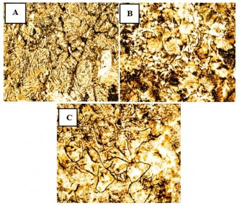
The optical microscope micrograph in Figure 3 shows the HAZ microstructure of gray cast iron welded by SMAW with ENi-CI electrode and without and with preheating. Thermal cycling affects the HAZ region most strongly since it exists between the weld zone and base metal area of the substrate. This study includes an in-depth examination of the figure and describes expected defects while explaining the microstructural changes.
Figure 3. FC 200 gray cast iron HAZ microstructures: (A) without preheating, (B) HAZ with 150℃ preheating, and (C) HAZ with 300℃ preheating
3.3.1 HAZ without preheating microstructure analysis
The HAZ microstructure without preheating reveals several significant characteristics in gray cast iron subjected to high heat input without preheating. Visible bright needle-like structures represent cementite or iron carbides formed due to fast cooling. No preheating leads to an extreme temperature gradient, reducing the duration for carbon diffusion and graphitization. The hard regions in steel are highly brittle carbides, while the regions between carbide structures exhibit darker appearances due to martensite [34]. The hardness of martensite and its brittleness causes a reduction in ductility within the HAZ. During the HAZ heating and fast cooling process, graphic material in cast iron shows evidence of partial dissolution and breakage of its existing structure. Nickel promotes graphitization in the weld zone, but the heated affected zone receives only partial benefits due to the base metal structures mainly changed by welding thermal cycles [35]. Widmanstätten carbide structures appear in gray cast iron when non-equilibrium cooling occurs. Sharp temperature drops in HAZ occur when preheating is not used, as they face an abrupt temperature disparity between the weld zone and base metal. Rapid cooling during the transformation process does not enable sufficient carbon diffusion for graphite formation, leading to carbide precipitation [36]. The ENi-CI electrode facilitates graphitization inside the weld area, but this transformation process stops before reaching most of the HAZ, making the original base metal more prone to Martensite formation.
Because of martensite and cementite creation, the area around the HAZ becomes exceptionally tough yet fragile. The phases do not possess mechanical stress absorption capacity that puts the joint at high risk of structural failure. The rapid-cooling-induced high residual stresses coupled with a brittle microstructure enables the HAZ to easily develop both cold cracks and HAZ cracks [37]. Most material fractures occur between grains or through carbide networks. Thermal fatigue cracks develop within carbide-rich areas because the HAZ undergoes dissimilar expansion and contraction patterns while cooling down from welding temperatures. The partial graphite dissolution process in HAZ regions decreases material ductility along with toughness properties that results in embrittlement. A substantial mechanical properties mismatch occurs between weld area and base material because of the very hard nature of martensite and cementite found within the HAZ. The mechanical property mismatch functions as a stress collector that raises failure risks.
3.3.2 HAZ with 150℃ preheating microstructure analysis
The microstructure of HAZ with 150℃ preheating appears partially refined, but traces of carbide formations and graphite networks remain visible. The preheating process at 150℃ led to more connected graphite networks but retained some areas of dissolution. The ferritic-pearlitic matrix of lighter areas represents improved material structure than the martensitic structure observed without preheating. Some carbide precipitate remains noticeable at grain boundaries, potentially causing hardness fluctuations in specific areas. The preheating process at 150℃ results in reduced martensitic formation, but some isolated martensite regions persist in rapidly cooled zones. The uneven darkness and patterning structures in the micrograph show carbon segregation, resulting in localized areas of varying hardness. Preheating at elevated temperatures prolongs carbon diffusion and limits graphite dissolution, resulting in a partly refined microstructure with visible heterogeneities [38]. The graphitization effect of ENi-CI (nickel-based electrode) extends to the weld metal region, while remaining restricted from the HAZ. The 150℃ preheat temperature achieves partial graphite stabilization but also permits some nickel atoms to spread, reducing carbides. Preheating minimizes thermal shock and decreases the probability of cold cracking but does not eliminate residual stresses from hard zones in specific areas. HAZ develops high susceptibility to embrittlement due to carbide retention, creating locations with different localized hardness levels. Load-induced brittleness occurs in HAZ grain boundaries due to carbon and impurities segregating, creating microcracks and stress concentration points. Cracking risks persist despite reduced thermal stresses, mainly affecting areas containing formed carbides [39].
3.3.3 HAZ with 300℃ preheating microstructure analysis
The micrograph in Figure 3(C) demonstrates an optimal 300℃ preheating of HAZ microstructure, exhibiting better graphite maintenance, reduced carbide development, and stronger mechanical properties. The cooling process at 300℃ prevents carbide formation, allowing carbon to remain as graphite. The ferritic-pearlitic matrix area shows lighter sections due to minimal carbide appearance. The material cools down at a slower pace, minimizing hard brittle carbide structures. Pearlitic structures alongside ferrite regions enable average material strength with additional toughness, while ferrite regions enhance ductility. The rate of cooling is too slow for martensite formation, as no needle-like martensitic structures form in the material. HAZ exhibits higher ductility and better resistance to cracking when preheating at 300℃ compared to temperatures below 200℃. The higher preheating temperature produces a homogenous HAZ with minimal micro segregation and stress concentration areas, preventing non-uniform phase distribution and promoting microstructural balance [40].
The microstructural examination of the HAZ arose due to the elevated preheating temperature, which reduced cooling rates and allowed carbon atom diffusion, resulting in graphite stabilization. The Ni content from the ENi-CI electrode improves carbon mobility, protecting graphite flakes from breakdown. Preheating at 300℃ with nickel use decreases thermal expansion discrepancies, enhances mechanical coupling between weld and base metal, and promotes a uniform phase transformation, resulting in refined grains and lesser microstructural flaws.
3.3.4 The comparison between the three (HAZ) microstructures
Cast iron welding requires preheating to control thermal gradients, carbon diffusion, phase transformations, and residual stress distribution in High-Altitude Graphite (HAZ). The HAZ microstructure exhibits extensive martensitic transformation, creating materials with high hardness and brittleness. Rapid cooling stops carbon diffusion, leading to iron carbide formations (Fe3C) at carbide networks. The initial graphite flakes of gray cast iron undergo severe fragmentation and dissolution during localized melting at the HAZ, resulting in Widmanstätten Structures formation and poor mechanical properties. This results in extreme hardness and brittleness, and HAZ cracking risk. Weld joints develop cold cracking and delayed cracking due to excessive residual stress, and weld quality suffers from defects that make the joint weak during loading events. No-preheating conditions leave behind more graphite flakes but exhibit chemical reactions to some extent. The Fe3C concentration decreases but several carbides continue appearing on grain boundaries. The presence of martensite in HAZ structures diminishes, but some hardened areas still exist. These conditions offer better resistance to crack formation compared to un-preheated HAZ zones, but still contain stress concentrations and carbide areas. The presence of graphite increases ductility, but segregation remains a phenomenon in specific zones. For 300℃ preheating, graphite maintains structural integrity, avoiding embrittlement, and minimal Fe3C precipitation. The structure becomes more ductile and crack-resistant when martensite does not form. The complete homogenization of the grain structure removes stress-concentrating areas, producing outstanding weld quality in HAZs.
Table 4. HAZ microstructures comparative at different preheating temperatures
|
Feature |
No Preheating |
150℃ Preheating |
300℃ Preheating |
|
Graphite Retention |
Poor (Significant graphite dissolution) |
Moderate (Partially retained) |
Excellent (Well-retained, continuous graphite network) |
|
Carbide Formation |
High (Extensive Fe3C carbides) |
Moderate (Localized carbides) |
Negligible (Minimal carbide formation) |
|
Martensitic Presence |
High (Brittle martensite regions) |
Low to Moderate (Some hard spots) |
Negligible (Ductile ferritic-pearlitic matrix) |
|
Stress & Cracking Risk |
High (Severe residual stress, cracking likely) |
Moderate (Reduced stress, but still some cracking risk) |
Very Low (Minimal residual stress, near-zero cracking risk) |
|
Grain Refinement |
Coarse grains with Widmanstätten features |
Moderate refinement |
Fine, well-distributed grains |
|
Weld Integrity |
Poor (Brittle HAZ, prone to failure) |
Moderate (Balanced microstructure but not fully optimized) |
Excellent (Optimized ductility, toughness, and stability) |
The results in above and in Table 4 analysis revealed that no preheat rapid cooling results in hard carbide formation and martensite material phases because carbon becomes trapped within them. The preheating at 150℃ enables some carbon to transform into graphite yet carbide phases continue to exist. 300℃ preheat temperature allows the cooling process to function efficiently to achieve both optimal graphite content alongside minimized carbide development. The application of nickel from ENi-CI electrodes helps graphite formation yet it reaches limited success when thermal management is inadequate in the welding HAZ. Enhancing preheating temperature from 300℃ enables nickel to maintain carbon stability thereby preventing the formation of carbides and martensite. The phase transformation control gets better and stress relaxes effectively because higher preheating reduces thermal stresses and decreases the probability of cold cracks and HAZ cracking. Table 5 summarized the relation between the HAZ analysis findings and its implications in HAZ integrity.
Table 5. HAZ analysis findings and its implications in HAZ integrity
|
Preheat Temperature |
300℃ Preheat |
150℃ Preheat |
No Preheat |
|
Graphite Stability |
Excellent (Fully Retained Graphite) |
Moderate (Partial Graphite Retention) |
Poor (Graphite Dissolution) |
|
Carbide Formation |
Negligible (Minimal Carbides) |
Moderate (Some Carbides) |
High (Carbides & Martensite) |
|
Residual Stress |
Very Low (Near-Zero Cracking Risk) |
Moderate (Some Residual Stress) |
High (Cold Cracks Likely) |
|
Hardness Variability |
Low (Uniform Hardness) |
Medium (Some Hard Zones) |
Very High (Brittle) |
|
Overall Weld Integrity |
Excellent |
Fair |
Poor |
4.1 No preheating (SEM) analysis
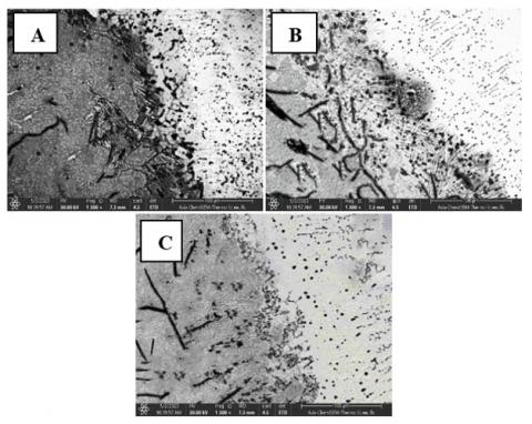
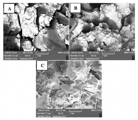
The study examines a gray cast iron weld joint using Shielded Metal Arc Welding (SMAW) and an ENi-CI electrode microstructure study. The weld zone (WZ) is a distinct section, with dendrite structures forming due to lacked equilibrium conditions in the cooling process. Nickel, along with graphite flakes and nodules, promotes graphitization. The ductile weld metal contains excessive nickel, minimizing excessive hardness. Excellent bond criteria between base and target metal are crucial, as defects at joint lines can trigger cracks to spread. Porosity and shrinkage cavities can result from gas entrapment or improper heat input. The fusion line is the vital contact area between weld metal and base metal. Structural weakness in the weld area can lead to delamination and cracking. Three likely defects are present: inadequate heat input, incomplete fusion, and hot and liquation cracking due to graphite or carbide segregation at grain boundaries.
The HAZ material exhibits maximum brittleness due to its dark coarse-grained microstructure. Rapid cooling produces martensitic and carbide-rich areas due to the absence of preheating steps. The graphite structure experienced a local melting stage before solidifying, increasing the risk of cracking. High stress-induced cracking tendencies result from the combination of martensite and Fe3C carbides in the material. Defects include cracking due to high residual stress during rapid cooling and cold cracking due to hydrogen embrittlement or stress concentration. The ENi-CI electrode supports graphite development exclusively within the weld area, resulting in brittle carbide networks. High thermal stresses in the steel base material increase the risk factors for hot cracking, incomplete fusion, and grain boundary embrittlement. When no preheating occurs the HAZ experiences sudden cooling that causes carbon to transform into hard cementite Fe3C and martensite phases instead of forming stable graphite [41]. As illustrated in Figure 4(A), the hard and brittle HAZ formed through this process easily fractures when subject to any stress. The massive temperature gap between WZ and the surrounding base metal precipitated harmful residual stresses throughout the fusion zone. Pressure from these stresses leads to three damaging effects that include hot cracking as well as incomplete fusion and grain boundary embrittlement. The ENi-CI electrode drives graphitization but this effect remains restricted to the welded area. The HAZ area underwent localized graphite dissolution that produced fragile carbide networks.
Figure 4. WZ, fusion line, and HAZ SEM: (A) without preheating, (B) HAZ with 150℃ preheating, and (C) HAZ with 300℃ preheating
4.2 150℃ preheating (SEM) analysis
The SEM image of gray cast iron weld joints, made through SMAW using an ENi-CI electrode at 150℃ preheating temperature in Figure 4(B), reveals dendritic structures with nickel as the dominant component. The distribution of graphite nodules shows good dispersion, suggesting that nickel partially acts as a graphitizing agent. Dendritic boundaries within the weld metal display little micro segregation of alloying elements, but this weakening pattern may create local hardness variations. Nickel's ability to inhibit carbide formation makes the WZ ductile, and mild variations in hardness may emerge due to segregation effects. The fusion line or transition zone shows partial melting occurrences, unfinished graphitization, and a sharp interface between weld metal and base metal. This combination results in moderate hardness, a transition mismatch, potential weak points due to incomplete bonding, residual stress zones, hot cracking risk, brittle regions, and unmelted graphite inclusions from the base metal graphite flakes. The Pearlitic-ferritic matrix displays carbide precipitates through HAZ microstructural observations. Carbide formation exists with reduced occurrence compared to untreated HAZs, promoting mechanical properties that exceed those of untreated HAZs by limiting carbide development. The microstructure shows delicate distribution and improved stress distribution and hardness variations, pointing to predicted defects. Carbide precipitation throughout the metal causes localized hardness variations and minor hardness inconsistencies. Stress levels remain moderate yet lower than without preheating, but some persisting cracking risks remain. Intergranular segregation in some areas exhibits carbon redistribution across grain boundaries, making these sections slightly harder compared to other parts of the material. The above three zones' microstructure analysis is summarized in Tables 6 and 7 for no preheating and 150℃ preheating cases.
Table 6. Three zones microstructural analysis
|
Zone |
Expected Defects |
Phase Composition |
Microstructural Characteristics |
|
WZ |
Moderate ductility, but potential for porosity and shrinkage cavities |
Austenite + Graphite + Ferrite |
Bright region with fine dendritic structures, nickel-rich solidification |
|
Fusion Line |
High residual stress, risk of hot cracking and incomplete fusion |
Nickel-stabilized austenite + Partial carbides |
Sharp transition with unmixed regions, dendritic growth, and possible grain boundary carbides |
|
HAZ |
Very high hardness, extreme brittleness, high crack sensitivity |
Martensite + Pearlite + Carbides |
Darker coarse grains, fractured graphite flakes, martensite/carbide structures |
Table 7. Three zones microstructural analysis
|
Zone |
Expected Defects & Mechanical Properties |
Phase Composition |
Microstructural Characteristics |
|
WZ |
Moderate ductility, possible micro segregation and porosity |
Austenite + Graphite + Ferrite |
Nickel-stabilized austenitic dendrites, graphite nodules dispersed in the matrix |
|
Fusion Line |
Residual stress zones, possible hot cracking |
Nickel-stabilized austenite + Pearlite + Carbides |
Fine dendritic structure, partial grain boundary melting, sharp transition to base metal |
|
HAZ |
Moderate hardness variation, reduced but present cracking risk |
Pearlite + Ferrite + Isolated Carbides |
Refined pearlitic-ferritic matrix, fragmented graphite flakes, some carbide precipitates |
The predetermined heating step slows down the process of cooling to inhibit the formation of extensive martensite. The formation of a ferritic-pearlitic matrix takes place instead of forming martensite. Nickel strengthening together with managed preheating temperatures allowed some graphite to persist in the HAZ thus minimizing brittleness. A complete elimination of carbides during transformation was not possible which resulted in some hard zones forming inside the HAZ. When steel fails to undergo preheating at no preheating strong thermal gradients create severe material stress that results in cracking. The gradient minimization at 150℃ reduces the number of cracks yet some stress persists at the fusion area.
4.3 300℃ preheating (SEM) analysis
The SEM was used to examine gray cast iron weldment produced by SMAW using ENi-CI electrodes, as demonstrated in Figure 4(C). The study evaluated phase transformations, microstructural variations, anticipated defects, and microstructural controlling factors. The WZ showed a weld metal with mostly austenite stabilized with nickel, which resists carbide formation. The uniform dendritic structure demonstrates good temperature control during heating and cooling processes. The mechanical qualities of the WZ were found to be excellent, with ductility and toughness characteristics, reducing potential weld failures due to mechanical strains.
Table 8. Three zones microstructural analysis
|
Zone |
Expected Defects |
Phase Composition |
Microstructural Characteristics |
|
WZ |
High ductility, minimal porosity, excellent fusion |
Austenite + Graphite + Ferrite |
Well-refined nickel-rich austenitic dendrites, uniform graphite distribution |
|
Fusion Line |
Very low stress concentration, strong metallurgical bonding |
Nickel-stabilized austenite + Pearlite |
Smooth transition with slight diffusion zones, minimal carbide formation |
|
HAZ |
Minimal hardness variations, very low cracking risk |
Pearlite + Ferrite + Graphite |
Highly refined pearlitic-ferritic matrix, well-retained graphite flakes, negligible carbides |
The anticipated defects include minimal porosity and negligible micro segregation due to proper solidification methods and nickel-promoting carbon diffusion patterns. The specimen displayed a clear fusion line between base metal and weld metal, with microstructural examinations showing an uninterrupted bond. The WZ released nickel to stabilize the fusion line, reducing the chance of forming brittle carbide precipitates. The HAZ showed a refined ferritic-pearlitic matrix structure, maintaining balanced mechanical properties. The formation of carbides was negligible, preventing hard spots inside the affected area. Ductility and toughness improved significantly when preheat temperature reached 300℃, ensuring prolonged mechanical stability. The anticipated defect level was minimal cracking due to the elimination of thermal expansion mismatches. High toughness and fatigue resistance were achieved due to the absence of martensitic formation. Table 8 above summarizes the essential microstructure characteristics of this case.
At 300℃ preheating temperatures, carbon diffusion stops carbide formation, while controlled cooling speed maintains elasticity in the microstructure. Preserving graphite flakes within the HAZ prevents cementite phase formation into brittle products. This improves mechanical characteristics and cracking resistance. Nickel addition through ENi-CI electrodes stabilizes austenite, achieving uniform graphite distribution throughout the weld area. Nickel diffusion within the fusion line eliminates hardness differences. The thermal expansion gradient is adjusted to prevent cold cracking and residual stress formation, resulting in superior mechanical durability and exceptional fatigue resistance. Table 9 below compares the microstructure characteristics between these three cases.
Table 9. Microstructural comparison across preheating temperatures
|
Zone |
300℃ Preheating |
150℃ Preheating |
No Preheating |
|
WZ |
Highly refined austenitic-ferritic structure, well-distributed graphite |
More uniform dendritic solidification, finer microstructure |
Nickel-stabilized austenite with coarse dendritic growth, porosity present |
|
Fusion Line |
Well-diffused transition, excellent metallurgical bonding |
Smoother transition, reduced carbide formation |
Sharp transition, carbide and martensite accumulation, weak bonding |
|
HAZ |
Highly refined ferritic-pearlitic matrix, excellent graphite retention, no carbide presence |
Partially refined ferritic-pearlitic structure, some carbide remnants |
High carbide content, martensitic transformation, severe hardness variations |
|
Cracking & Residual Stress Risk |
Very low (optimal stress distribution and ductility) |
Moderate (reduced stress, but some carbide formation persists) |
High (due to rapid cooling and brittle HAZ) |
|
Overall Weld Integrity |
Excellent (optimized ductility, toughness, and stability) |
Moderate (balanced microstructure, but not fully optimized) |
Poor (brittle HAZ, prone to failure) |
4.4 Comparative SEM microstructural analysis of gray cast iron weld joint at different preheating temperatures
The WZ examinations reveal nickel-stabilized austenite dendritic matrix structures with microscopic pores and segregations. A rapid transition exists in the fusion line due to strong thermal gradients and deficient material diffusion. Carbides and martensite in high quantity within the HAZ area generate extreme brittleness and high hardness, increasing the risk of cold-crack failures. High hardness in the HAZ zone weakens weld resistance to thermal and mechanical loading stresses, increasing the risk of brittle fracture and early failure under service conditions. At 150℃, the WZ analysis shows an improved structure due to nickel controlling dendrites to smaller sizes and decreasing material segregation. WZ thermal gradients are reduced, and the widened fusion line spreads out carbide formation areas. The HAZ includes refined ferritic-pearlitic microstructures and remaining carbide precipitates. A slower cooling process decreases carbide development within the HAZ, preventing material deterioration. The retention of graphite materials increases while ductility levels rise, eliminating the chance of material failure through cracking. The fusion line strength surpasses the no preheating condition but contains detectable zones that concentrate stresses. The weld quality level is moderate and provides minimal cracking hazard but retains some material hardness areas. The preheated condition produced better results than non-preheating, but maximum optimization was not achieved. SEM observations at 300℃ show a well-refined WZ containing evenly distributed austenitic-ferritic dendrites, an excellent metallurgical bond, and an ideal combination of ferritic-pearlitic matrix and fully preserved graphite flakes. The welding process achieves precise zero stress levels and enduring mechanical system stability. A fully refined microstructure represents the best preheating temperature for welds in cast iron.
4.5 Preheating temperature influence on residual stress distribution
Comprehensive evaluation examined residual stress changes regarding preheating temperature within WZ. Experimental outcomes show that preheating temperature directly affects tensile residual stress decrease. Preheating temperatures below 200℃ leads to high residual stress retention since weld cooling rates from metal to base material create excessive shrinkage stress. More elevated preheating temperatures between 300 and 400℃ lead to decreased residual stress levels because thermal gradients normalize while stress relieving mechanisms enhance. The research group conducted systematic statistical investigations to create mathematical estimates between preheating temperature levels and residual stress results. Different preheating temperatures resulted in residual stresses measurement. This regression model describes the analyzed data as:
$\sigma_T=\alpha e^{-\beta T P}+C$ (1)
where, σT is the residual stress (MPa), TP is the preheating temperature (℃), α and β are material-dependent coefficients, C is an asymptotic stress limit. The proposed model showed strong reliability because of high correlation coefficient (R2>0.95) that regression analysis produced. Analysis shows minor additional residual stress relief only occurs beyond 350℃ specific preheating temperature.
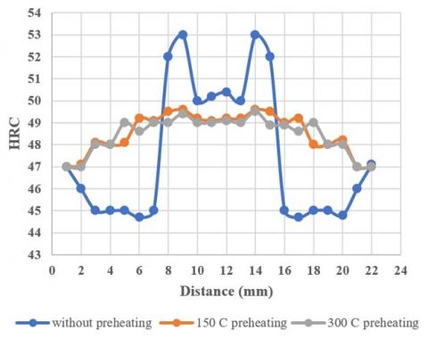
The provided data in Figure 5 below demonstrates Rockwell hardness (HRC) distribution measurement results from a gray cast iron weldment processed through SMAW with ENi-CI electrode without preheating, 150℃ and 300℃ preheating temperature. Hardness changes analysis needs to focus on Base Metal (BM), HAZ, Fusion Line (FL), and WZ. The non-preheated welding joint exhibited a base metal hardness of 46-47 HRC, with graphite flakes serving as stress concentration points. The hardness of the HAZ attained 44-46 HRC, as the welding heat cycles induced a decrease in hardness attributed to the formation of ferrite and coarsened pearlite. This diminishes the mechanical performance of welding and influences its chemical makeup. The Fusion Line (FL) region of cast iron has a hardness value of 53 HRC due to microstructural changes and rapid cooling processes. This area is prone to hydrogen-induced cracking and brittleness, and the WZ has hardness values between 50-51 HRC. Rapid cooling generates white iron (Fe3C), making the material highly brittle and increasing its sensitivity to mechanical cracking.
Figure 5. Rockwell hardness profile (A) without preheating (B) 150℃ preheating (C) 300℃ preheating
The 150℃ hardness profile chart shows gray cast iron base initial hardness of 47 HRC, attributed to its graphitic microstructure. The HAZ increases from 47 HRC to 48.5 HRC due to welding thermal cycles. The Fusion Line (FL) has the hardest microstructure with an approximately 49.5 HRC hardness level. The nickel-based ENi-CI electrode leads to increased hardness in this area due to nickel diffusion within the metal mass and solidification shrinkage. The hardness in the WZ area varies slightly but remains at 49 HRC. Weld components made from ENi-CI electrode material contain a nickel-enriched weld metal structure, enhancing material ductility without a significant reduction in hardness levels. The WZ contains nickel-stabilized austenitic formations and carbide precipitates, leading to intermediate hardness levels. Preheating at 150℃ achieves minor hardness reduction, preventing major material cracking issues. The 300℃ hardness profile of gray cast iron showed a base metal with a 47 HRC hardness value, which remains unaffected by welding processes. The HAZ shows toughness ranges from 47 to 48.8 HRC, with 150℃ preheat exhibiting increasing hardness. The sluggish cooling pattern from 300°C preheating impedes hard martensitic and carbide-rich structure evolution, making the structure less susceptible to cracking. The nickel diffused from the ENi-CI electrode helps decrease embrittlement in this zone. Fusion line (FL) showed 49.3 HRC hardness, below 150℃ welded hardness. The increased preheat temperature created a small degree of fusion line softening, reducing the chances of cold cracking. The nickel-based electrode (ENi-CI) still results in increased hardness in this area due to solidification shrinkage and carbide precipitation. WZ hardness values range from 48.8 to 49.5 HRC, with mild variations between 48.8- 49.5 HRC.
5.1 Gray cast iron weldments hardness profiles comparison
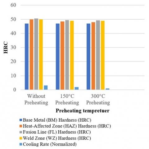
SMAW produces different hardness patterns in gray cast iron weldments through the use of an ENi-CI electrode depending on the welding temperature at which preheating takes place. The studied cases include: Without Preheating, 150℃, Preheating, and 300℃ Preheating. This study provides a comprehensive scientific breakdown of how preheating methods affect weld hardness levels together with microstructural changes and weld structural integrity. The base metal hardness remains steady at around 47 HRC due to welding heat, while the HAZ section achieves hardness levels above 50 HRC. Fast cooling weakens the HAZ, causing martensitic transformation. Preheating at 150℃ reduces martensite formation, while 300℃ preheating results in the lowest HAZ hardness at 48 HRC. This results in pearlite with excellent ductility and toughness.
Table 10. Three cases hardness profile comparison
|
Feature |
300℃ Preheating |
150℃ Preheating |
Without Preheating |
|
Base Metal (BM) Hardness |
~47 HRC |
~47 HRC |
~47 HRC |
|
(HAZ) Hardness |
~48 HRC (Lowest Stress, Best Ductility) |
~48.5–49 HRC (Moderate Stress) |
50+ HRC (Brittle, High Stress) |
|
Fusion Line (FL) Hardness |
~49.3 HRC (Least Carbides, Best Toughness) |
~49.5 HRC (Less Carbides, Still Hard) |
~50.5 HRC (High Carbides, Most Brittle) |
|
WZ Hardness |
~49 HRC (Most Uniform, Lowest Stress) |
~49 HRC (More Uniform, Less Stress) |
~50 HRC (Fluctuates, High Internal Stress) |
|
Cooling Rate |
Slowest (Minimal Martensite, More Pearlite) |
Moderate (Less Martensite) |
Fastest (Martensitic Formation) |
|
Residual Stresses |
Lowest (Best Weld Integrity) |
Moderate (Lower Cracking Risk) |
Very High (Cold Cracking Risk) |
|
Ductility |
High (Best Ductility and Toughness) |
Moderate |
Very Low (Brittle) |
|
Carbide Formation |
Low (More Uniform, Less Cracking) |
Moderate (Some Carbide Precipitation) |
High (Embrittlement at FL and HAZ) |
|
Microstructural Stability |
Best (Stable, Low Hardness Variation, Less Cracking) |
Improved (Less Cracking, Some Hard Zones Exist) |
Poor (High Risk of Cracking & Failure) |
|
Suitability for Machining |
Best (Most Machinable, Lowest Hardness Variations) |
Moderate (Still Hard in Some Zones) |
Poor (Too Hard & Brittle for Machining) |
The hardness level at the fusion line reaches its peak due to carbide precipitation and rapid cooling at 50.5 HRC when preheating does not occur. The extreme embrittlement behavior in this area creates dangers regarding possible material fracture. The reduction of carbide precipitation through 150℃ preheating leads to less brittle material while decreasing the hardness to ~49.5 HRC. The hardness level at 300 degrees Celsius preheating amounts to ~49.3 HRC which provides better material ductility compared to non-preheated conditions. The material shows a smoother structure comprising reduced carbide formations. This present scenario demonstrates the best outcome for cracking prevention among all cases tested. The WZ's hardness measures around 50 HRC along with slight variations when preheating is absent. The material experiences significant internal stresses at this temperature range that may lead to cracking occurrence. This weldment displays the lowest internal stress and best ductility due to which it remains the most stable option. Table 10 summarized this comparison parameters.
For more explanation about the hardness profile and summarized these results in best way, the authors represented these results in the following graphic chart in Figure 6 below.
Figure 6. Rockwell hardness profile graphical bars chart
The SEM images showing tensile test gray cast iron weldments samples fracture the likely defects at preheating temperatures of no preheat, 150℃ and 300℃. This section provides an overview of all microstructural features together with their related cracking and defect characteristics. Figure 7 below illustrated the tensile test fracture SEM. Non preheated tensile test fracture SEM sample analysis in Figure 7(A) exhibits brittle fractures due to non-preheating effects. Areas containing coarse microstructures along with their low ductility feature among these observations. Corrosion tracks across the area of grey cast iron primarily through grain boundaries in a transgranular type. Thermal stresses should not have developed during welding thanks to inadequate preheat operations particularly where the fusion zone is located. The presence of such stresses leads to crack starts occurring either at the surface or at inclusions. The rapid cooling of gray cast iron tends to produce shrinkage cracks because of its inherent sensitivity. The cooling processes without preheating treatment was likely accelerated through the absence of preheating treatment thus leading to crack formation. The absence of preheating would increase the susceptibility to brittle fractures in gray cast iron thus decreasing energy absorption during the tensile test.
In Figure 7(B), The thermal gradient decreased when preheating at 150℃ due to the slower cooling dynamics. The microstructure becomes more uniform due to this process which might reduce the brittle phases. The crack pattern shows enhanced ductility characteristics than the first sample despite the presence of fracture across both grain boundaries and large carbide regions. The preheating process reduces thermal stress which contributes to cracking formation. Welded parts affected by carbides remain at risk for developing cracks that run parallel to the grain boundaries. The carbide formation in gray cast iron weldments in specific areas developed cracking initiation sites and creates local hardness fluctuations. The preheating applied before welding enhances the toughness of the weld area by minimizing brittleness but the developed ductility remains below specific application needs.
300℃ temperature preheating leads to microstructure with an extended cooling process resulting in a refined microstructure that lowers the occurrence of brittle cementite or other hard phases that lead to material fractures. 150℃ preheated specimen failure surface exhibited better ductile tearing than the 300℃ preheating sample. The slow cooling results in decreased shrinkage cracking by developing lower thermal gradients across the weld. The improved uniformity of weld microstructure contributes to a better material ductility. The material exhibits signs of dimples and ductile fracture features that indicate better tensile stress absorption until failure occurred. Preheating the weldment to 300℃ diminishes the formation of residual stresses because every part reaches a uniform higher temperature that lowers the possibility of cracks from differential cooling effects.
Figure 7. Tensile test fracture SEM: (A) without preheating, (B) 150℃ preheating, and (C) 300℃ preheating
Assessing best preheating temperature cost-effectiveness for welded cast iron materials plays vital role in deciding its financial practicability in production facilities. Preheating temperature optimization for welded cast iron materials will require financial analysis to demonstrate its value. Financial analysis reviews both energy expenses and material savings together with labour productivity and total operational consequences. The preheating system needs energy input which usually comes from electric or gas-powered heating systems. Energy analysis depends heavily on price per kilowatt-hour (kWh) and fuel litter unit. energy assessment related expenses through preheating temperature combinations at 100℃, 200℃ and 300℃ enables increased understanding. Weld quality improves through preheating because it reduces cracking occurrence together with porosity and residual stress. Expenses decrease when organizations eliminate need for rework and reject parts. Analysis examines both discarded materials expenses as well as welding consumable expenses between various preheating practices. Welding speed together with cooling rate receive direct influence from preheating procedure which affects production output. Analysis incorporates hourly labour expenses while examining how extended preheating times benefit from reduced weld repairs after finishing work. Having elevated preheating temperatures leads to extended handling requirements which influence both cycle operation duration and manufacturing output rates. Better weld strength extends the lifespan of components which decreases both maintenance expenses and replacement costs especially benefiting industries that weld cast iron parts like automotive and heavy machinery sectors because of increased reliability. Weld failures number decreases which decrease time production lines total amount remain idle. Return on Investment (ROI) Calculation, preheating expenses assessed against long-term financial savings to determine cost-benefit relationship. using optimal preheating temperatures economic feasibility depends on NPV and payback period analysis.
This research study demonstrates that preheating serves as a fundamental parameter for achieving superior microstructural and mechanical properties of welded gray cast iron. The research demonstrated through controlled analysis that preheat temperature elevation impacts the retention of graphite as well as carbide formation degree and stress residual patterns. Preheating to 300℃ leads to best weld quality by enhancing mechanical stability while preventing brittle phase development. Desirable weldments with minimal defects require strict thermal control according to these research findings. This study yields essential findings which serve as the following summary.
1. The microstructure, mechanical properties together with overall integrity of welded cast iron substantially improve when preheat temperatures rise. The retention of graphite along with lower carbide formation and reduced residual stress occurs when preheating temperatures increase.
2. The best outcomes from testing scenarios occur when preheating materials to 300℃, which yields optimal weld properties, combined with excellent ductility and minimal carbides, narrowed hardness ranges, and enhanced material durability. The preheating process before welding improves mechanical stability as well as durability and operational functioning of welded components.
3. Preheating a weld to 150℃ produces better quality than non-heated samples but fails to eliminate the formation of carbides and residual stress. The weld shows diverse hardness patterns and contains some susceptibility to cracking.
4. Without preheating during welding operations, the resultant material develops brittle qualities through the formation of hard martensitic zones that create more cracks because of fast cooling. Poor mechanical performance occurs because the microstructure does not possess uniform characteristics that leads to weak bonding.
5. Nickel-based electrodes with ENi-CI composition help stabilize austenite and allow graphitization that minimizes carbide development. The complete advantages of nickel stabilization appear when combined with suitable thermal management techniques (preheating).
6. Preheating helps control cooling rates that prevents thermal stress from creating defects during the process. A 300℃ preheating process reduces residual stress thus creating stable weldments that show strong resistance to fatigue.
7. The optimal temperature for SMAW welding of gray cast iron with ENi-CI electrodes using 300℃ preheat results in maximum mechanical properties alongside minimal weld defects and long-lasting weld structure. However, when only moderate weld quality is required 150℃ can be effective and no preheating should be employed due to enhanced cracking potential from brittleness changes.
8. The obtained research data indicates that preheating temperatures between 150℃ and 300℃ represent most suitable range. Heat treatment at 150℃ lowers carbide formation and reduces martensite phases that leads to minor improvement in HAZ hardness to approximately 49 HRC. 300℃ preheating temperature strikes best equilibrium by maintaining graphite while reducing carbide formation to produce an overall better microstructure for ductile weld joints. HAZ hardness variations reach 48 HRC as lowest possible level under this condition thus minimizing brittle fracture chances.
9. Welded joints effectiveness depends on how much preheating temperature selected by operators. Engineering applications requiring structural durability together with moderate mechanical properties should use 150℃ preheating temperature. Temperature range provides advantages to industries that prioritize both operations speed and affordable production costs.
[1] Kumar, R., Kumar, M., Trivedi, V., Bhatnagar, R. (2017). Evaluation of mechanical and microstructural properties of cast iron with effect of pre heat and post weld heat treatment. SSRG International Journal of Mechanical Engineering, 4(5): 1-6. https://doi.org/10.14445/23488360/IJME-V4I5P101
[2] Dametew, A.W. (2015). Experimental investigation on weld ability of cast iron. Science Discovery, 3(6): 71-75. https://doi.org/10.11648/j.sd.20150306.15
[3] Gouveia, R.M., Silva, F.J., Paiva, O.C., Andrade, M.F., Silva, L., Moselli, P.C., Papis, K.J. (2017). Study of the heat-treatments effect on high strength ductile cast iron welded joints. Metals, 7(9): 382. https://doi.org/10.3390/met7090382
[4] White, C. (2017). Welding of Cast Irons. ASM Handbook.
[5] Saffer, J., Dörres, T., Schaumberger, K., Ermer, J., Kaufmann, F., Wittmann, A., Schmidt, M. (2020). Laser beam welding of heat-resistant mixed joints using laser-based pre-and post-heating. Procedia CIRP, 94: 671-675. https://doi.org/10.1016/j.procir.2020.09.105
[6] Yuan, J., Ji, H., Zhong, Y., Cui, G., Xu, L., Wang, X. (2023). Effects of different pre-heating welding methods on the temperature field, residual stress and deformation of a Q345C steel butt-welded joint. Materials, 16(13): 4782. https://doi.org/10.3390/ma16134782
[7] Gouveia, R.M., Silva, F.J., Paiva, O.C., Andrade, M.D. F., Pereira, L.A., Moselli, P.C., Papis, K.J. (2018). Comparing the structure and mechanical properties of welds on ductile cast iron (700 MPa) under different heat treatment conditions. Metals, 8(1): 72. https://doi.org/10.3390/met8010072
[8] Srivastava, B.K., Tewari, S.P., Prakash, J. (2010). A review on effect of preheating and/or post weld heat treatment (PWHT) on mechanical behavior of ferrous metals. International Journal of Engineering Science and Technology, 2(4): 625-631.
[9] Akinribide, O.J., Ogundare, O.D., Oluwafemi, O.M., Ebisike, K., Nageri, A.K., Akinwamide, S.O., Olubambi, P.A. (2022). A review on heat treatment of cast iron: Phase evolution and mechanical characterization. Materials, 15(20): 7109. https://doi.org/10.3390/ma15207109
[10] Bhatnagar, R.K., Gupta, G. (2016). A review on weldability of cast iron. International Journal of Scientific & Engineering Research, 7(5): 126-131.
[11] Radaj, D. (2012). Heat effects of welding: Temperature field, residual stress. Distortion. Springer Science & Business Media. https://doi.org/10.1007/978-3-642-48640-1
[12] Liu, M., Kouadri-David, A., Ma, G. (2024). Residual stress relaxation in the laser welded structure after low-cycle fatigue and fatigue life: Numerical analysis and neutron diffraction experiment. Coatings, 14(3): 281. https://doi.org/10.3390/coatings14030281
[13] Gucwa, M., Winczek, J., Mičian, M. (2020). The effect of preheating on the properties of wear-resistant welds. Welding Technology Review 92(2): 7-14. https://doi.org/10.26628/wtr.v92i2.1096
[14] Dhara, L.N., Biswas, P. (2025). Influence of induction preheating and post weld heat treatment for reducing delta ferrite content and improving mechanical properties of induction assisted gas metal arc welding of modified 9Cr-1MoV steel. Journal of Materials Engineering and Performance, 34(2): 1149-1168. https://doi.org/10.1007/s11665-024-09161-8
[15] Charkhi, M., Akbari, D. (2019). Experimental and numerical investigation of the effects of the pre-heating in the modification of residual stresses in the repair welding process. International Journal of Pressure Vessels and Piping, 171: 79-91. https://doi.org/10.1016/j.ijpvp.2019.02.006
[16] Chamim, M., Triyono, Diharjo, K. (2017). Effect of electrode and weld current on the physical and mechanical properties of cast iron welding. AIP Conference Proceedings, 1788(1): 030031. https://doi.org/10.1063/1.4968284
[17] Behnam, M.J., Davami, P., Varahram, N. (2010). Effect of cooling rate on microstructure and mechanical properties of gray cast iron. Materials Science and Engineering: A, 528(2): 583-588. https://doi.org/10.1016/j.msea.2010.09.087
[18] Adedayo, A.V. (2013). Relationship between graphite flake sizes and the mechanical properties of grey iron. International Journal of Materials Science and Applications, 2(3): 94-98. https://doi.org/10.11648/j.ijmsa.20130203.14
[19] Dauod, D.S., Mohammed, M.S., Aziz, I.A., Abbas, A.S. (2023). Mechanical vibration influence in microstructural alterations and mechanical properties of 304 stainless steel weld joints. Journal of Engineering Science and Technology, 18(6): 33-54.
[20] Hamdey, M.D., Mohammed, M.S., Kareem, A.H., Majdi, H.S. (2024). Thermal and mechanical analysis in joint welding of thick steel alloy plates with and without backing plate. Journal of Engineering Science and Technology, 19(5): 1974-1989.
[21] Santos, D.N., de Souza Costa, M.C.M., Vaz, C.T. (2021). Influence of preheating temperature and post-weld heat treatment on microstructural and mechanical characteristics of the heat-affected zone in nodular cast irons with ferritic-pearlitic matrix. Journal of the Brazilian Society of Mechanical Sciences and Engineering, 43(8): 381. https://doi.org/10.1007/s40430-021-03099-x
[22] Cárcel-Carrasco, J., Pascual, M., Pérez-Puig, M., Segovia, F. (2017). Comparative study of TIG and SMAW root welding passes on ductile iron cast weldability. Metalurgija, 56(1-2): 91-93.
[23] Dong, Z., Li, Y., Lee, B., Babkin, A., Chang, Y. (2022). Research status of welding technology of ferritic stainless steel. The International Journal of Advanced Manufacturing Technology, 118(9): 2805-2831. https://doi.org/10.1007/s00170-021-08128-6
[24] Thornton, R., Slatter, T., Jones, A.H., Lewis, R. (2011). The effects of cryogenic processing on the wear resistance of grey cast iron brake discs. Wear, 271(9-10): 2386-2395. https://doi.org/10.1016/j.wear.2010.12.014
[25] Fontanari, V., Benedetti, M., Girardi, C., Giordanino, L. (2016). Investigation of the lubricated wear behavior of ductile cast iron and quenched and tempered alloy steel for possible use in worm gearing. Wear, 350: 68-73. https://doi.org/10.1016/j.wear.2016.01.006
[26] Ghaini, F.M., Ebrahimnia, M., Gholizade, S. (2011). Characteristics of cracks in heat affected zone of ductile cast iron in powder welding process. Engineering Failure Analysis, 18(1): 47-51. https://doi.org/10.1016/j.engfailanal.2010.08.002
[27] Dutta, T., Dey, S., Datta, S., Das, D. (2019). Designing dual-phase steels with improved performance using ANN and GA in tandem. Computational Materials Science, 157: 6-16. https://doi.org/10.1016/j.commatsci.2018.10.020
[28] Yıldızlı, K., Karamış, M.B., Nair, F. (2006). Erosion mechanisms of nodular and gray cast irons at different impact angles. Wear, 261(5-6): 622-633. https://doi.org/0.1016/j.wear.2006.01.042
[29] Reisgen, U., Oechsner, M., Sharma, R., Ellermeier, J., Andersohn, G., Engler, T., Gonzalez Olivares, E. (2020). Influence of preheating on lamellar gray cast iron for surface layer welding applications with plasma-transferred arc powder and metal inert gas welding processes with duplex steel as filler material. Journal of Thermal Spray Technology, 29(4): 724-740. https://doi.org/10.1007/s11666-020-01014-9
[30] Ocelík, V., De Oliveira, U., De Boer, M., De Hosson, J.T.M. (2007). Thick Co-based coating on cast iron by side laser cladding: Analysis of processing conditions and coating properties. Surface and Coatings Technology, 201(12): 5875-5883. https://doi.org/10.1016/j.surfcoat.2006.10.044
[31] Mohammed, M.S., Hamdey, M.D., Kareem, A.H., Majdi, H.S. (2024). Investigation of copper backing plate effects in stainless steel welding distortion, heat distribution, and residual stress. International Journal of Heat & Technology, 42(4): 1434-1446, https://doi.org/10.18280/ijht.420433
[32] Sarkar, T., Pramanick, A.K., Pal, T.K. (2015). Some aspects on the welding characteristics and formation of microstructures in a newly developed coated electrode for austempered ductile iron (ADI). Indian Welding Journal, 48(4): 44-60. https://doi.org/22486/iwj/2015/v48/i4/126050
[33] Yu, S.K., Loper Jr, C.R. (1988). The effect of molybdenum, copper, and nickel on the pearlitic and martensitic hardenability of ductile cast irons. Transactions of the American Foundrymen's Society, 96: 811-822.
[34] Pascual, M., Cembrero, J., Salas, F., Martínez, M.P. (2008). Analysis of the weldability of ductile iron. Materials Letters, 62(8-9): 1359-1362. https://doi.org/10.1016/j.matlet.2007.08.070
[35] El-Shennawy, M., Omar, A.A. (2010). Similar and dissimilar welding of ductile cast iron. In Proceedings of the 36th International MATADOR Conference, London, pp. 297-302. https://doi.org/10.1007/978-1-84996-432-6_68
[36] Carrasco, J.C., Vicente, F.S., Corral, A.M., Guillamón, M.P. (2022). Weldability of ductile cast iron using AISI-316L stainless steel ER rod. Revista de Metalurgia, 58(3): e224-e224. https://doi.org/10.3989/revmetalm.224
[37] García-Lira, J., Curiel-Reyna, E., Curiel-Razo, Y., Lara-Guevara, A., Rojas-Rodríguez, I. (2021). Characterization of dissimilar welding between 304 stainless steel and gray iron using nickel coated electrode. Materials Sciences and Applications, 12(12): 614-621. https://doi.org/10.4236/msa.2021.1212041
[38] Kolukisa, S. (2007). The effect of the welding temperature on the weldability in diffusion welding of martensitic (AISI 420) stainless steel with ductile (spheroidal graphite-nodular) cast iron. Journal of Materials Processing Technology, 186(1-3): 33-36. https://doi.org/10.1016/j.jmatprotec.2006.11.148
[39] Aglan, H.A., Ahmed, S., Prayakarao, K.R., Fateh, M. (2013). Effect of preheating temperature on the mechanical and fracture properties of welded pearlitic rail steels. Engineering, 5(11): 837-843. http://doi.org/10.4236/eng.2013.511101
[40] Derakhshan, E.D., Yazdian, N., Craft, B., Smith, S., Kovacevic, R. (2018). Numerical simulation and experimental validation of residual stress and welding distortion induced by laser-based welding processes of thin structural steel plates in butt joint configuration. Optics & Laser Technology, 104: 170-182. https://doi.org/10.1016/j.optlastec.2018.02.026
[41] Amin, S.A., Abdulhasan, A.A., Mohammed, M.S., Majdi, H.S. (2024). Experimental and numerical study of maximum welding joint temperature impacts in alloy steel pipe welding microstructure, distortion, corrosion resistance, and mechanical properties. Revue des Composites et des Matériaux Avancés-Journal of Composite and Advanced Materials, 34(6): 775-786. https://doi.org/10.18280/rcma.340612