Mohamed Chaqouri*![]() | Adel Deraoui
| Adel Deraoui![]() | Mohamed Maniana
| Mohamed Maniana![]() | Fouad Erchiqui
| Fouad Erchiqui![]() | Abdelali Tajmouati
| Abdelali Tajmouati![]()
© 2025 The authors. This article is published by IIETA and is licensed under the CC BY 4.0 license (http://creativecommons.org/licenses/by/4.0/).
OPEN ACCESS
The principal challenge is to develop an adequate braking system that satisfies the criteria for heat transfer, size and weight. A considerable amount of research has been carried out to solve the various problems associated with the thermal and mechanical performance of vehicle disc brakes. Analysis has become both easier and more effective with the widespread application of digital tools. In a disc brake, two types of discs are used: solid disc and ventilated disc. This study sought to investigate the influence of geometry on the performance of a ventilated disc. Three tests were conducted: case 1 solid disc, case 2 ventilated disc with prismatic vanes, and case 3 ventilated disc with circular vanes. The particularity of this trail is the study of the geometric shape of the circular vanes. The results of this study show that the choice of ventilated disc geometry affects both the thermal and mechanical performance of the braking system. Among the ventilated discs case 2 presents a better result in temperature on the other hand the ventilated disc case 3 presents a better result in constraint.
disc, friction, temperature, finite element method, stress
Disc braking systems are among the vehicle's critical components and are constantly subjected to non-linear transient thermoelastic conditions [1]. Designing a braking system that achieves the desired performance while reducing weight and size is a real challenge. Brake discs must withstand friction torque and dissipate the heat generated by braking [2]. The braking system performance of a vehicle is affected mainly by temperature increase at the contact area(disc/pad). Rising temperatures result in accelerated wear, heat distortion, heat cracking, fading of brakes, vaporization of brake fluid, instability of thermoelastic properties, squealing of brakes and bearing failure.
These various factors directly impact the performance and service life of the braking system, as well as the vehicle's safety [3-10].
This means that adequate disc cooling is essential for comfortable braking and safe braking, particularly in high-performance vehicles. To dissipate friction heat efficiently, ventilated brake discs of the centrifugal fan type, have been designed [11]. Regardless of the configuration of the heat dissipation components between disc and pad, the ventilated rotor available on the market fall into two categories: standard brake discs and cross-drilled brake discs [12]. Since the advent of brake discs in the 1960s [13], several experimental and theoretical attempts have been made to understand the thermofluidic properties and improve the cooling efficiency of standard brake discs, as reported by Yan et al. [14]. Wallis [15] conducted several dynamometer tests on standard radially finned, cross-bored ventilated brake discs. He found that the cross-bores reduced the braking distance by applying a specific brake pressure and also lowered the disc temperature. Antanaitis and Rifici [16] showed that the cooling performance of cross-bored brake discs was superior to that of standard discs.
Belhocine and Bouchetara [17] applied ANSYS CFX to modelling cast iron thermal behavior in all braking modes. The results of the simulation, however, indicate considerable contribution of radial ventilation to disc cooling in the braking phase. Ghadimi et al. [18] confirmed experimentally how complex ventilated disc structures affect the local heat transfer coefficient distribution. Belhocine and Bouchetara [19] aim to identify the geometric design factor of the disc. The present study focused on brake pads with ventilated brake discs. Using coupled thermo-structural analysis, the strain and Von-Mises stress developed in the disc were determined. The results of this study indicate a complete coupling between thermal and mechanical behaviors produced by braking phenomena. As well as mechanical stresses causing fatigue cracks, fractures and wear in the disc, the findings of the study indicate that the disc's temperature, maximum equivalent stress and total deformation rise as the thermal stress increases. Manjunath and Suresh [20] investigated the performance of a vehicle disc brake rotor under severe braking conditions. A thermal structural analysis was applied to solve the st Von-Mises stress produced in the disc for two cases. The models are solid and ventilated rotor types with two different materials. The results of the study indicate that the ventilated cast-iron disc reduces temperature, stress and deformation compared with the solid disc.
In view of the above, this knowledge provides brake design engineers with constructive advice for further improving cross-drilled brake discs. The present study stipulates the effect of disc fin geometry on temperature and mechanical stresses during the braking and cooling process.
Other recent research work has shown the interest of ventilated discs, through thermomechanical studies [21, 22].
2.1 Geometric modeling and braking conditions
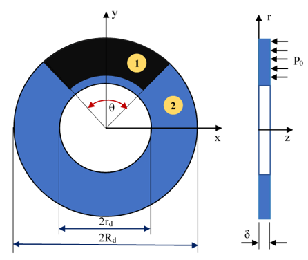
The brake disc has a constant angular velocity $\omega_0$. The contact between disc rotor and pads is maintained at a constant pressure (Figure 1). Due to friction, the disc's angular velocity reduces linearly until time $t=t_s$. At this point, there is thermal friction in the area of contact. Figure 2 illustrates the development of the vehicle's velocity over the various phases of simulation.
Figure 1. Braking system model. (1): Pad, (2) Disc rotor
Figure 2. Vehicle’s velocity-evolution
2.2 Thermal problem modeling
The immobile pad is pressed against the disc's friction surface, generating a constant and uniformly distributed friction pressure $p_0$, which prevents movement and angular velocity reduces linearly with time of simulation:
$\omega(t)=\omega_0\left(1-\frac{t}{t_s}\right)$ (1)
The heat produced by friction q(r, t) is dissipated by conduction and by convection around the free boundaries. In addition, the following assumptions are made:
- Perfect contact is maintained during braking.
- Coefficient of friction depends on temperature.
- Thermophysical properties of materials are independent of temperature.
The thermal flux caused by friction can be expressed as follows [21]:
$q_d(r, t)=\gamma \eta q(r, t)$ (2)
$q(r, t)=f p_0 r \omega_0\left(1-\frac{t}{t_s}\right)$ (3)
Here, $\eta=\frac{K_d \sqrt{\alpha_p}}{K_d \sqrt{\alpha_p}+K_p \sqrt{\alpha_d}}$ is the heat distribution factor and $\gamma= \frac{\theta}{2 \pi}$ is the overlap factor.
The heat generated at the boundary is dissipated by convection. The heat conduction in the disc and pad is also included in the model and expressed by the following equation:
$\rho C_p \frac{\partial T}{\partial t}+\nabla(-K \nabla T)=Q$ (4)
All parameters of this expression are defined in Table 3. The per unit volume $Q\left(W \cdot m^{-3}\right)$, set to zero in this case. It is assumed that for temperatures lower than the start temperature of phase transformation in the solid state 723℃ and that there is no heat source or sink inside the volume studied.
With the above assumptions, the equation governing the temperature distribution of the brake rotor in the transient regime are described in cylindrical coordinates. Using the finite element method, the temperature field is solved according to the following equation:
$\begin{gathered}\frac{\partial^2 T}{\partial r^2}+\frac{1}{r} \frac{\partial T}{\partial r}+\frac{\partial^2 T}{\partial z^2}=\frac{1}{\alpha} \frac{\partial T}{\partial z} ; r_d \leq r \leq R_d ;-\delta \leq z \leq 0 ; \\ t>0\end{gathered}$ (5)
Boundary conditions.
The braking process generates heat at the contact surface, as described in expression (2). The convection process involves the dissipation of heat from the system's free surfaces to the surrounding air:
$\left.k_d \frac{\partial T}{\partial z}\right|_{z=0}=\left\{\begin{array}{c}q_d(r, t) ; r_d \leq r \leq R_d ; 0 \leq t \leq t_{\text {end }} \\ h\left[T_0-T(r, 0, t)\right] ; r_d \leq r \leq R_d ; t>0\end{array}\right.$ (6)
$\left.k_d \frac{\partial T}{\partial z}\right|_{z=-\delta}=h\left[T_0-T(r, 0, t)\right] ; r_d \leq r \leq R_d ; t>0$ (7)
$\left.k_d \frac{\partial T}{\partial z}\right|_{r=r_d}=h\left[T\left(r_d, z, t\right)-T_0\right] ;-\delta \leq z \leq 0 ; t>0$ (8)
$\left.k_d \frac{\partial T}{\partial r}\right|_{r=R_d}=h\left[T_0-T\left(R_d, z, t\right)\right] ;-\delta \leq z \leq 0 ; t>0$ (9)
The convective film coefficient is referred by h W/m2.K, the thermal-diffusivity is referred by $\alpha\left(m^2 / s\right)$, and $T_0$ is the reference temperature 293.15 K.
The following formula can be used to calculate the convective film coefficient h as a function of the speed v of the vehicle:
$h=\left\{\begin{array}{l}2 \frac{k}{L} \frac{0.338 P r^{1 / 3} R e^{1 / 2}}{\left(1+\left(\frac{0.0468}{P r}\right)^{2 / 3}\right)^{1 / 4}} ; \text { if } R e \leq 5.10^5 \\ 2 \frac{k}{L} P r^{1 / 3}\left(0.037 R e^{4 / 5}-871\right) ; \text { if } R e \leq 5.10^5\end{array}\right.$ (10)
where, $\operatorname{Pr}=\frac{c_{p a} \mu_a}{k_a} ; \operatorname{Re}=\frac{2 \rho_a r v}{\mu_a}$.
Here, the density $\rho_a$, conductivity $k_a$, viscosity $\mu_a$ and specific heat capacity $C_{p a}$, are provided for ambient air.
Initial condition is expressed as follows:
$T(r, z, t)=T_0 ; t=0 s$ (11)
2.3 Mechanical problem modeling
In the case of deformation caused by thermal stress, the invariant form of the dynamic equilibrium equation can be expressed as follows [20]:
$\nabla \sigma+F=\rho \frac{\partial^2 u}{\partial z^2}$ (12)
In the case of a homogeneous, elastic isotropic material, the constitutive equation is as follows:
$\sigma=E\left(\varepsilon-\varepsilon_0\right)+\sigma_0$ (13)
Assuming no prestressing, the self-deformation resulting from thermal expansion can be calculated as follows:
$\varepsilon_0=\alpha_T \Delta T$ (14)
With u representing the displacement due to thermal deformation, F the negligible body force and $\alpha_T$ the coefficient of thermal expansion of the material.
Thermal conduction problem at boundaries (1)-(11) and thermoelasticity problem at boundaries (12)-(14) were both solved using the finite element method (FEM), implemented in the software package Comsol Multiphysics 6.1. The computational mixture included the elements shown in Table 1. The element density near the friction heating zone, where high temperature gradients and thermal stresses occur, was increased. Solving the heat conduction problem (1)-(11) was found with step ∆t = 0.25 s during braking and ∆t = 1s during acceleration of the disc. The obtained values of the temperature at the nodes of the spatial network were used as the input data for solving the thermoelasticity problem (12)-(14).
Table 1. Meshing
|
Cases |
Domain Elements |
Edge Elements |
Boundary Elements |
Mesh Volume |
|
1 |
3510 |
445 |
2157 |
294600 |
|
2 |
3060 |
605 |
2604 |
172870 |
|
3 |
4928 |
578 |
3164 |
172870 |
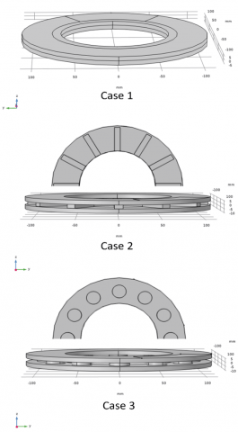
This study focuses on three brake disc profiles, as illustrated in Figure 3.
Figure 3. Tree forms of disc geometry: (case 1) solid disc, (case 2) vented disc with straight vanes, (case 3) vented disc with circular vanes
The design was calculated based on an FMK11 metal-ceramic pad and a ChNMKh cast iron disc. The dimensional, thermal and mechanical data are listed in Tables 2 and 3 [22]. The current calculation model includes the effect of temperature and stresses on disc behavior by introducing the thermal distribution factor η.
Table 2. Dimensional data
|
Parameters |
Value |
|
Disc thickness: $\delta(\mathrm{mm})$ |
10 |
|
Weight of vehicle: M (kg) |
1016.2 |
|
Angle fitting: $\theta(\operatorname{deg})$ |
64.5 |
|
Pad's radius: $R_p, r_p(\mathrm{~mm})$ |
113.5;76.5 |
|
Disc's radius: $R_d, r_d(\mathrm{~mm})$ |
113.5;66 |
Table 3. Thermals, mechanicals and kinematics data
|
Parameters |
Value |
|
Thermal capacity: $C p \cdot(J / k g . K)$ |
7100 |
|
Conductivity: $k \cdot(W / m \cdot K)$ |
500 |
|
Emissivity: $\epsilon$ |
0.32 |
|
Young’s modulus: $E(G P a)$ |
100 |
|
Poisson's ratio of disc: $v$ |
0.25 |
|
Initial velocity: $V_0\left(m \cdot s^{-1}\right)$ |
27.78 |
|
Deceleration: $a\left(m \cdot s^{-2}\right)$ |
500 |
|
Braking time: $t_s(s)$ |
5.9 |
|
Final time: $t_{\text {end }}(s)$ |
30 |
The thermomechanical behavior of the disc during braking is studied through the evolution of temperature and the mechanical stresses of the brakes.
4.1 Influence of disc vane geometry on evolution temperature
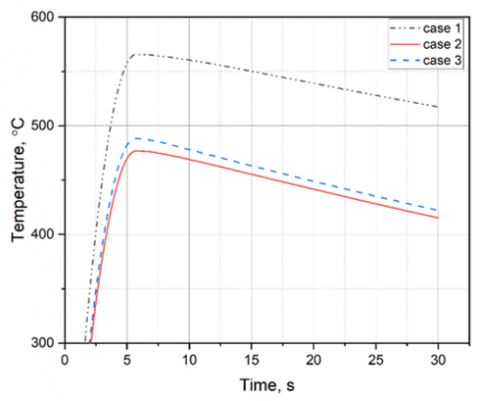
Figure 4 shows a comparison between the evolutions over time of the maximum temperatures reached during braking in the three test cases.
We can see that the solid disc (case 1) is the hottest, with a maximum temperature of around 560℃. The other two-disc types (case 2 and case 3) have lower temperatures than those in the case 1 disc (around 475℃).
From this initial result, we can see that the ventilated shape of the brake discs is more efficient, from a heat dissipation, than the solid shape.
Figure 4. Average disc temperature during time of simulation
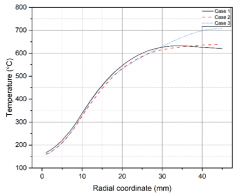
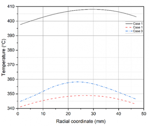
Figure 5 shows the radial distribution of the maximum temperature recorded at time t = 4.75 s before the end of braking for the three test cases.
Figure 5. Radial temperature evolution at time 4.75 s
It can be seen that at the edge of the disc (Rd) the temperature is slightly higher for the solid disc case (case 1) compared to the ventilated discs (case 2 and case 3), while inside the discs between radius rd and Rd the temperatures for the three test cases are similar.
After 25 s of braking action, the radial distribution of the maximum temperature for the three test cases is shown in Figure 6. We note that the ventilated discs (case 2 and case 3) cool down more quickly than the solid disc (case 1), this is done thanks to the presence of air channels which promote the evacuation of heat by forced convection.
Figure 6. Radial temperature repartition at time 30 s
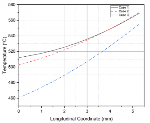
At time (t = 5.75 s) and in the axial symmetry plane of the disk, the average temperature varies from depth (Z = 0 mm) to depth (Z = 5 mm), ranging from a minimum value of 415℃ to a maximum temperature of 565℃ for the three test cases. The temperature evolution curves are shown in Figure 7.
Figure 7. Axial temperature evolution at time 4.75 s
Based on this temperature distribution for the three test cases, it is also observed that the ventilated disks cool more quickly compared to the solid disk and that the geometry model (case 3) is more favorable compared to (case 2).
4.2 Influence of disc vane geometry on temperature evolution and Von Mises stresses
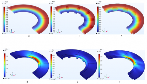
The Von Misses stress developed in disc brakes as shown in Figures 8(d), (e), (f) depend mainly on the disc configuration applied. This means that the stress created on the disc is directly linked to the availability of the vanes on the disc, accelerating heat transfer. In fact, the stress exerted on the ventilated disc brake in case 2 has a maximum value of 530 MPa compared with the other discs studied, whereas the ventilated disc in case 3 has a stress closer to that of the folded disc. The results show that the presence of vanes for air flow can increase the Von Misses stress occurring at the eastern surface, particularly for the right-hand vanes (see Figure 8(e)). The comparison between case 2 and case 3 leads to the conclusion that the vane geometry impacts the heat transfer efficiency, as well as the Von Misses stress.
Figure 8. Temperature distribution versus disc volume (a, b, c). Stress distribution versus disc volume (d, e, f)
Figures 8(a), (b), (c) show that the ventilated rotors have a lower temperature between pad/ disc. On the other hand, solid disc brakes have the highest contact surface temperature. This is explained mainly because a solid rotor has less of an advantage in dissipating the heat generated by friction.
While Figures 8(d), (e), (f) represent the stress concentration in the three cases of disk geometry.
The other hand, ventilated rotors have a greater ability to dissipate heat with ambient temperature. The fins on the disc accelerate the cooling process.
The objective of this study was to conduct a thermomechanical analysis of three-disc designs. Model 1: solid disc, Model 2: ventilated disc with straight vanes, and Model 3: ventilated disc with circular vanes.
In all three test cases, the maximum temperature is located at the maximum radius. Under the same braking conditions, the maximum temperature reached, 543℃, is obtained in the solid disc. In the Type 2 disc, the maximum temperature reached is 435℃, but in the Type 3 disc, the temperature reached is around 444℃. From this comparative study, we note that the geometry has a significant influence on disc cooling.
However, the analysis of the Von mises stresses shows that the 250 MPa solid disc is less stressed than the 500 MPa case 2 ventilated disc, which offers the best thermal performance.
From these three test cases we conclude that the geometry of the ventilated shapes improves the thermal disc performance but at the expense of mechanical resistance.
We find that the case of ventilated discs with rectangular vanes improves cooling performance but reduces the disc's fracture toughness. However, the case of ventilated discs with circular vanes only slightly improves cooling without affecting mechanical strength.
We conclude that to improve braking performance in disc brakes, we must solve the problem of coupling mechanical strength and heat transfer. And ventilated disc geometry is the best solution for improving disc brake performance, except that you need to choose the right ventilation blade geometry. And in our case, circular geometry is the best solution.
Thanks to Maniana M. and Tajmouati A. for their writing guidance and for his theoretical guidance.
[1] Kao, T.K., Richmond, J.W., Moore, M.W. (1994). The application of predictive techniques to study thermo-elastic instability of brakes (No. 942087). SAE Technical Paper. https://doi.org/10.4271/942087
[2] Anderson, A.E., Knapp, R.A. (1990). Hot spotting in automotive friction systems. Wear, 135(2): 319-337. https://doi.org/10.1016/0043-1648(90)90034-8
[3] Hartsock, D.L., Fash, J.W. (2000). Effect of pad/caliper stiffness, pad thickness, and pad length on thermoelastic instability in disk brakes. Journal of Tribology, 122(3): 511-518. https://doi.org/10.1115/1.555394
[4] Panier, S., Dufrénoy, P., Weichert, D. (2004). An experimental investigation of hot spots in railway disc brakes. Wear, 256(7-8): 764-773. https://doi.org/10.1016/S0043-1648(03)00459-9
[5] Majcherczak, D., Dufrénoy, P. (2006). Dynamic analysis of a disc brake under frictional and thermomechanical internal loading. Archive of Applied Mechanics, 75: 497-512. https://doi.org/10.1007/s00419-005-0431-4
[6] Jung, S.P., Park, T.W., Chai, J.B., Chung, W.S. (2011). Thermo-mechanical finite element analysis of hot judder phenomenon of a ventilated disc brake system. International Journal of Precision Engineering and Manufacturing, 12(5): 821-828. https://doi.org/10.1007/s12541-011-0109-5
[7] Maniana, M., Chaqouri, M., Benkachcha, S., Tajamouati, A. (2023). Thermomechanical study of a disc brake. In 2023 3rd International Conference on Innovative Research in Applied Science, Engineering and Technology (IRASET), Mohammedia, Morocco, pp. 1-4. https://doi.org/10.1109/IRASET57153.2023.10152984
[8] Maniana, M., Azime, A., Errchiqui, F., Tajmouati, A. (2022). Analytical and numerical analysis of thermal transfer in disc brake. International Journal of Heat and Technology, 40(3): 693-698. https://doi.org/10.18280/ijht.400305
[9] Chaqouri, M., Maniana, M., Tajamouati, A. (2023). Thermal and structural study of a brake disc using COMSOL. In 2023 7th IEEE Congress on Information Science and Technology (CiSt), Agadir - Essaouira, Morocco, pp. 411-414. https://doi.org/10.1109/CiSt56084.2023.10410002
[10] Chaqouri, M., Maniana, M., Tajmouati, A. (2024). Influence of pad geometry on the thermomechanical study of a disc brake. International Journal of Information Science and Technology, 8(3): 21-27. http://dx.doi.org/10.57675/IMIST.PRSM/ijist-v8i3.257
[11] Yan, H.B., Feng, S.S., Yang, X.H., Lu, T.J. (2015). Role of cross-drilled holes in enhanced cooling of ventilated brake discs. Applied Thermal Engineering, 91: 318-333. https://doi.org/10.1016/j.applthermaleng.2015.08.042
[12] Chatterley, T.C., Macnaughtan, M.P. (1999). Cast iron brake discs-current position, performance and future trends in Europe. SAE Transactions 1999-01-0141. https://doi.org/10.4271/1999-01-0141
[13] Thomas, T.H. (1967). Disc brakes “two years after”. SAE Technical Paper 670197. https://doi.org/10.4271/670197
[14] Yan, H.B., Zhang, Q.C., Lu, T.J. (2015). An X-type lattice cored ventilated brake disc with enhanced cooling performance. International Journal of Heat and Mass Transfer, 80: 458-468. https://doi.org/10.1016/j.ijheatmasstransfer.2014.09.060
[15] Wallis, L.M. (2003). A comparison of bi-directional disc brake rotor passage designs. Doctoral Dissertation, UNSW Sydney. https://doi.org/10.26190/unsworks/21331
[16] Antanaitis, D., Rifici, A. (2006). The effect of rotor crossdrilling on brake performance. SAE Transactions 2006-01-0691. https://doi.org/10.4271/2006-01-0691
[17] Belhocine, A., Bouchetara, M. (2012). Thermal analysis of a solid brake disc. Applied Thermal Engineering, 32: 59-67. https://doi.org/10.1016/j.applthermaleng.2011.08.029
[18] Ghadimi, B., Kowsary, F., Khorami, M. (2013). Thermal analysis of locomotive wheel-mounted brake disc. Applied Thermal Engineering, 51(1-2): 948-952. https://doi.org/10.1016/j.applthermaleng.2012.10.051
[19] Belhocine, A., Bouchetara, M. (2014). Structural and thermal analysis of automotive disc brake rotor. Archive of Mechanical Engineering, 61(1): 89-113. https://doi.org/10.2478/meceng-2014-0005
[20] Manjunath, T.V., Suresh, P.M. (2013). Structural and thermal analysis of rotor disc of disc brake. International Journal of Innovative Research in Science, Engineering and Technology, 2(12): 7741-7749.
[21] Wang, C., Wang, S., Jin, H., Huo, H., Xu, H., Chen, Z. (2022). Thermal-mechanical coupling analysis and optimization of mine hoist brake disc. Advances in Mechanical Engineering, 14(6). https://doi.org/10.1177/16878132221106297
[22] Jafari, R., Akyüz, R. (2022). Optimization and thermal analysis of radial ventilated brake disc to enhance the cooling performance. Case Studies in Thermal Engineering, 30: 101731. https://doi.org/10.1016/j.csite.2021.101731